
*LIT186160226*
WaveRunner
GP800R
SERVICE MANUAL
F0W-28197-1A-11LIT-18616-02-26

E
NOTICE
This manual has been prepared by Yamaha primarily for use by Yamaha dealers and their
trained mechanics when performing maintenance procedures and repairs to Yamaha equip-
ment. It has been written to suit the needs of persons who have a basic understanding of the
mechanical and electrical concepts and procedures inherent in the work, for without such
knowledge attempted repairs or service to the equipment could render it unsafe or unfit for
use.
Because Yamaha has a policy of continuously improving its products, models may differ in
detail from the descriptions and illustrations given in this publication. Use only the latest edi-
tion of this manual. Authorized Yamaha dealers are notified periodically of modifications and
significant changes in specifications and procedures, and these are incorporated in succes-
sive editions of this manual.
A10001-0*
WaveRunner GP800R
SERVICE MANUAL
©2000 by Yamaha Motor Corporation, USA
1st Edition, November 2000
All rights reserved.
Any reprinting or unauthorized use
without the written permission of
Yamaha Motor Corporation, USA
is expressly prohibited.
Printed in USA
LIT-18616-02-26

E
HOW TO USE THIS MANUAL
MANUAL FORMAT
All of the procedures in this manual are organized in a sequential, step-by-step format. The
information has been compiled to provide the mechanic with an easy to read, handy refer-
ence that contains comprehensive explanations of all disassembly, repair, assembly, and
inspection operations.
In this revised format, the condition of a faulty component will precede an arrow symbol and
the course of action required will follow the symbol, e.g.,
●
Bearings
Pitting/scratches
→
Replace.
To assist you in finding your way through this manual, the section title and major heading is
given at the top of every page.
ILLUSTRATIONS
The illustrations within this service manual represent all of the designated models.
CROSS REFERENCES
The cross references have been kept to a minimum. Cross references will direct you to the
appropriate section or chapter.
E
IMPORTANT INFORMATION
In this Service Manual particularly important information is distinguished in the following
ways.
The Safety Alert Symbol means ATTENTION! BECOME ALERT! YOUR SAFETY IS
INVOLVED!
WARNING
Failure to follow WARNING instructions could result in severe injury or death
to the machine
operator, a bystander, or a person inspecting or repairing the watercraft.
CAUTION:
A CAUTION indicates special precautions that must be taken to avoid damage to the water-
craft.
NOTE:
A NOTE provides key information to make procedures easier or clearer.
IMPORTANT:
This part has been subjected to change of specification during production.
E
HOW TO USE THIS MANUAL
1
To help identify parts and clarify procedure steps, there are exploded diagrams at the start
of each removal and disassembly section.
2
Numbers are given in the order of the jobs in the exploded diagram.
3
Symbols indicate parts to be lubricated or replaced (see “SYMBOLS”).
4
A job instruction chart accompanies the exploded diagram, providing the order of jobs,
names of parts, notes in jobs, etc.
5
Dimension figures and the number of parts, are provided for fasteners that require a tight-
ening torque.
Example:
Bolt or screw size : M10 (D)
×
25 mm (L)
6
Jobs requiring more information (such as special tools and technical data) are described
sequentially.
10 × 25 mm
D
L
E
A50001-1-4
SYMBOLS
Symbols
1
to
9
are designed as thumb-
tabs to indicate the content of a chapter.
1
General Information
2
Specifications
3
Periodic Inspection and Adjustment
4
Fuel System
5
Power Unit
6
Jet Pump Unit
7
Electrical System
8
Hull and Hood
9
Trouble analysis
Symbols
0
to
E
indicate specific data:
0
Special tool
A
Specified liquid
B
Specified engine speed
C
Specified torque
D
Specified measurement
E
Specified electrical value
[Resistance (
Ω
), Voltage (V), Electric current
(A)]
Symbol
F
to
H
in an exploded diagram
indicate the grade of lubricant and the loca-
tion of lubrication point:
F
Apply YAMALUBE 2-W oil or TC-W3 cirtified
outboard oil
G
Apply water resistant grease
(Yamaha grease A, Yamaha marine grease)
H
Apply molybdenum disulfide grease
Symbols
I
to
N
in an exploded diagram
indicate the grade of the sealing or locking
agent, and the location of the application
point:
I
Apply Gasket Maker
®
J Apply Yamabond #4
(Yamaha bond number 4)
K Apply LOCTITE
®
No. 271 (Red LOCTITE)
L Apply LOCTITE
®
No. 242 (Blue LOCTITE)
M Apply LOCTITE
®
No. 572
N Apply silicone sealant
NOTE:
In this manual, the above symbols may not
be used in every case.
12
34
56
78
90
AB
CD
EF
GH
IJ
KL
MN
GEN
INFO
SPEC
INSP
ADJ
FUEL
POWR
JET
PUMP
–+
ELEC
HULL
HOOD
TRBL
ANLS
T
R
.
.
E
A
M
GM
4
271
LT
242
LT
572
LT
LT
SS
E
INDEX
GENERAL INFORMATION
1
GEN
INFO
SPECIFICATIONS
2
SPEC
PERIODIC INSPECTION AND
ADJUSTMENT
3
INSP
ADJ
FUEL SYSTEM
4
FUEL
POWER UNIT
5
POWR
JET PUMP UNIT
6
JET
PUMP
ELECTRICAL SYSTEM
7
ELEC
HULL AND HOOD
8
HULL
HOOD
TROUBLE ANALYSIS
9
TRBL
ANLS
–+
A30000-0


E
1
2
3
4
5
6
7
8
9
GEN
INFO
CHAPTER 1
GENERAL INFORMATION
IDENTIFICATION NUMBERS......................................................................... 1-1
PRIMARY l.D. NUMBER........................................................................... 1-1
ENGINE SERIAL NUMBER ...................................................................... 1-1
JET PUMP UNIT SERIAL NUMBER ........................................................ 1-1
HULL IDENTIFICATION NUMBER (H.l.N.).............................................. 1-1
SAFETY WHILE WORKING ...................................................................... 1-2
FIRE PREVENTION................................................................................... 1-2
VENTILATION........................................................................................... 1-2
SELF-PROTECTION.................................................................................. 1-2
OILS, GREASES AND SEALING FLUIDS................................................ 1-2
GOOD WORKING PRACTICES................................................................ 1-3
DISASSEMBLY AND ASSEMBLY........................................................... 1-4
SPECIAL TOOLS............................................................................................. 1-5
MEASURING ............................................................................................ 1-5
REMOVAL AND INSTALLATION ............................................................ 1-6
1-1
E
GEN
INFO
IDENTIFICATION NUMBERS
A60700-0*
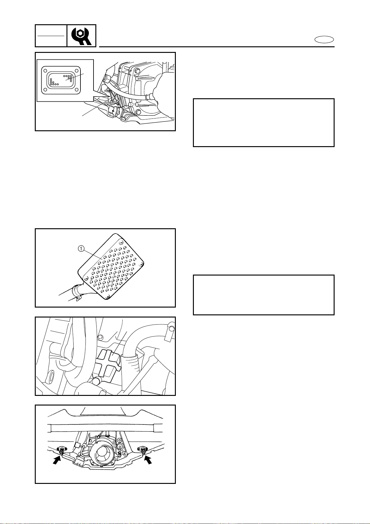
IDENTIFICATION NUMBERS
PRIMARY l.D. NUMBER
The primary l.D. number is stamped on a
label attached to the inside of the engine
compartment.
Starting primary l.D. number:
F0W: 800101–
ENGINE SERIAL NUMBER
The engine serial number is stamped on a
label attached to the cylinder head.
Starting serial number:
68A: 000101–
JET PUMP UNIT SERIAL NUMBER
The jet pump unit serial number is stamped
on a label attached to the intermediate
housing.
Starting serial number:
68A: 800101–
HULL IDENTIFICATION NUMBER
(H.l.N.)
The H.l.N. is stamped on a plate attached to
the aft deck.
1-2
E
GEN
INFO
SAFETY WHILE WORKING
SAFETY WHILE WORKING
The procedures given in this manual are
those recommended by Yamaha to be fol-
lowed by Yamaha dealers and their
mechanics.
FIRE PREVENTION
Gasoline (petrol) is highly flammable.
Gasoline vapor is explosive if ignited.
Do not smoke while handling gasoline
(petrol) and keep it away from heat, sparks,
and open flames.
VENTILATION
Gasoline vapor is heavier than air and is
deadly if inhaled in large quantities. Engine
exhaust gases are harmful to breathe.
When test-running an engine indoors,
maintain good ventilation.
SELF-PROTECTION
Protect your eyes with suitable safety spec-
tacles or safety goggles when grinding or
doing any operation which may cause parti-
cles to fly off.
Protect hands and feet by wearing safety
gloves or protective shoes if appropriate to
the work you are doing.
OILS, GREASES AND SEALING
FLUIDS
Use only genuine Yamaha oils, greases,
and sealing fluids or those recommended
by Yamaha.
1-3
E
GEN
INFO
SAFETY WHILE WORKING
Under normal conditions of use there
should be no hazards from the use of the
lubricants mentioned in this manual, but
safety is all-important, and by adopting
good safety practises any risk is minimized.
A summary of the most important precau-
tions is as follows:
1. While working, maintain good stan-
dards of personal and industrial
hygiene.
2. Clothing which has become contami-
nated with lubricants should be
changed as soon as practicable and
laundered before further use.
3. Avoid skin contact with lubricants (e.g.,
do not place a soiled rag in your
pocket).
4. Hands and any other part of the body
which have been in contact with lubri-
cants or lubricant-contaminated cloth-
ing should be thoroughly washed with
hot water and soap as soon as practica-
ble.
5. To protect the skin, the application of a
suitable barrier cream to the hands
before working is recommended.
6. A supply of clean lint-free cloths should
be available for wiping purposes.
GOOD WORKING PRACTICES
1. The right tools
Use the recommended special tools to
protect parts from damage. Use the
right tool in the right manner – do not
improvise.
2. Tightening torque
Follow the tightening torque instruc-
tions. When tightening bolts, nuts and
screws, tighten the larger sizes first and
tighten inner-positioned fixings before
outer-positioned ones.
1-4
E
GEN
INFO
SAFETY WHILE WORKING
3. Non-reusable items
Always use new gaskets, packings, O-
rings, oil seals, split-pins, circlips, etc.,
on reassembly.
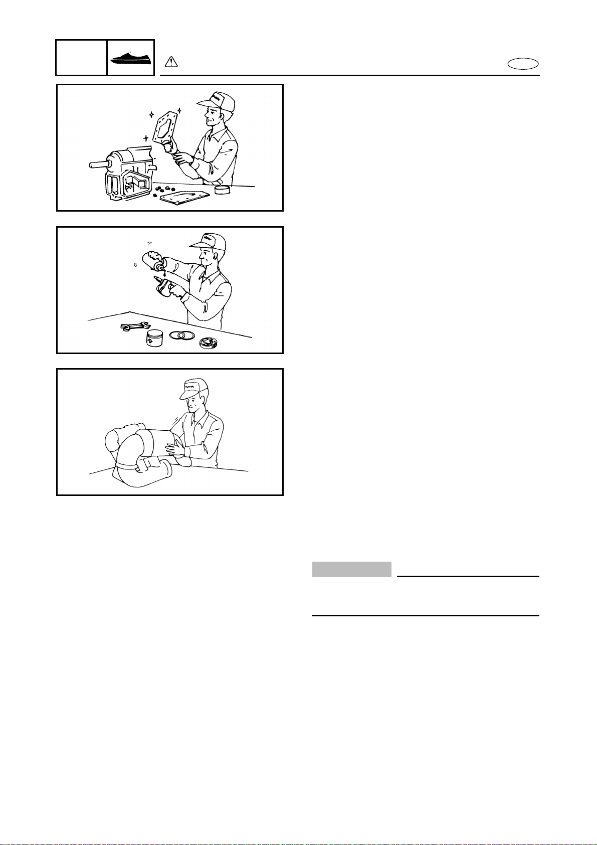
DISASSEMBLY AND ASSEMBLY
1. Clean parts with compressed air when
disassembling.
2. Oil the contact surfaces of moving parts
during assembly.
3. After assembly, check that moving parts
operate normally.
4. Install bearings with the manufacturer’s
markings on the side exposed to view
and liberally oil the bearings.
CAUTION:
Do not spin bearings with compressed air
because this will damage their surfaces.
5. When installing oil seals, apply a light
coat of water-resistant grease to the
outside diameter.
1-5
E
GEN
INFO
SPECIAL TOOLS
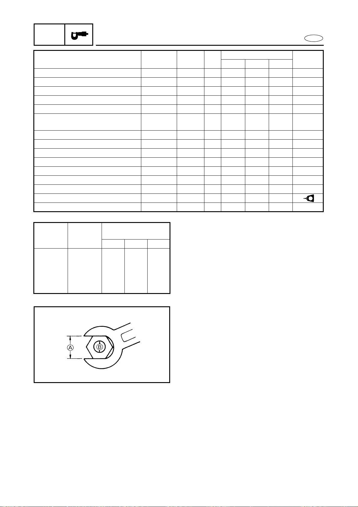
SPECIAL TOOLS
Using the correct special tools recom-
mended by Yamaha, will aid the work and
enable accurate assembly and tune-up.
Improvisations and using improper tools
can damage the equipment.
NOTE:
● For U.S.A. and Canada, use part numbers
starting with “J-”, “YB-”, “YM-”, “YU-” or
“YW-”.
● For other countries, use part numbers
starting with “90890-”.
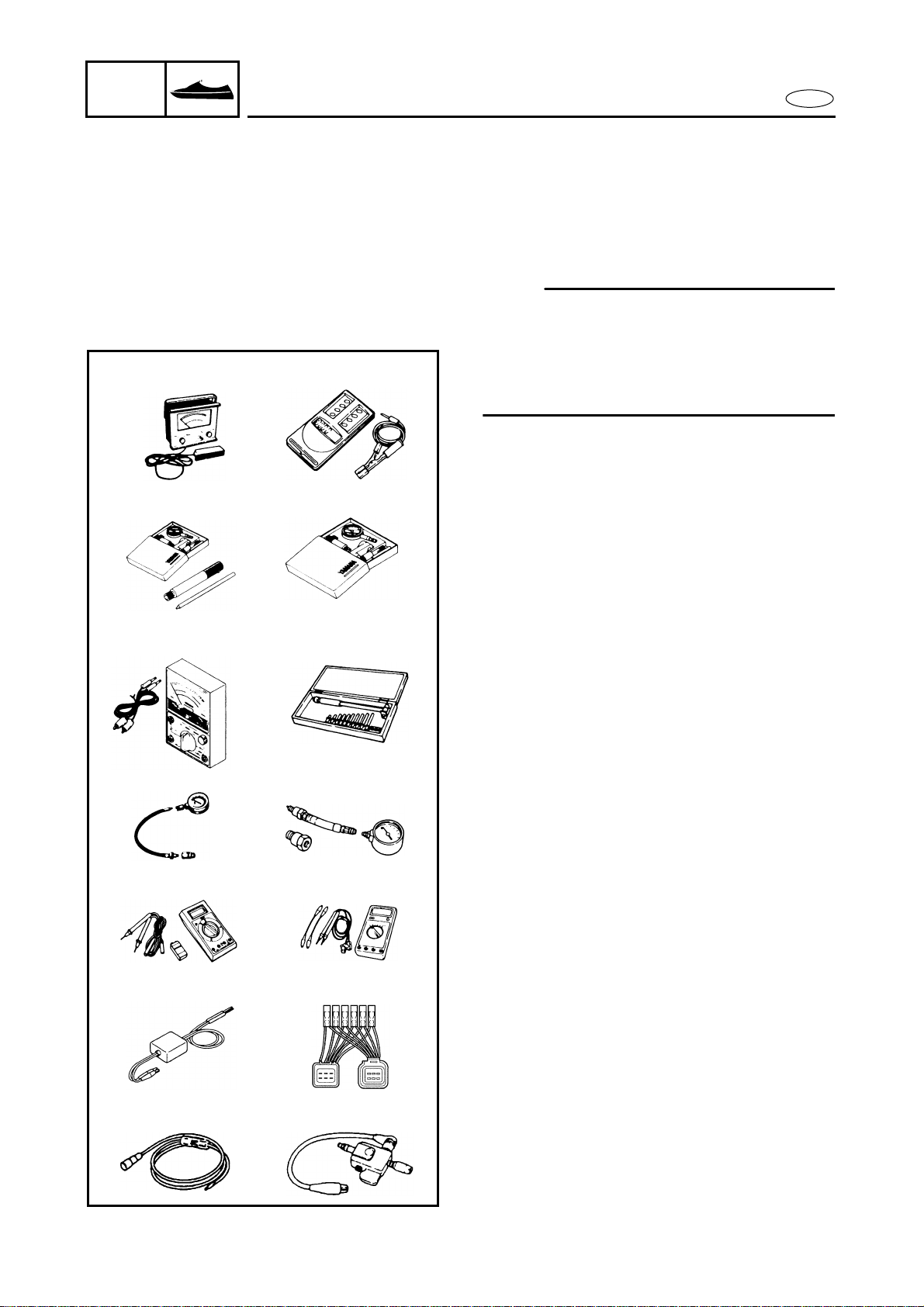
MEASURING
1 Engine tachometer
P/N. YU-8036-A
90890-06760
2 Dial gauge and stand
P/N. YU-03097, YU-01256
90890-01252
3 Pocket tester
P/N. YU-03112
90890-03112
4 Cylinder gauge set
P/N. YU-03017
90890-06759
5 Compression gauge
P/N. YU-33223
90890-03160
6 Digital tester
P/N. J-39299
90890-06752
7 Peak voltage adapter
P/N. YU-39991
90890-03169
8 Peak voltage test harness
P/N. YW-06779
90890-06779
9 Spark gap tester
P/N. YM-34487
90890-06754
43
1
2
5
6
87
9
YU-8036-A 90890-06760
YU-03097
YU-01256
90890-01252
YU-03112
90890-03112
YU-03017
90890-06759
YU-33223 90890-03160
J-39299 90890-06752
YU-39991
90890-03169
YW-06779
90890-06779
YM-34487 90890-06754
1-6
E
GEN
INFO
SPECIAL TOOLS
REMOVAL AND INSTALLATION
1 Coupler wrench
P/N. YW-06551
90890-06551
2 Flywheel holder
P/N. YW-06550
90890-06550
3 Flywheel puller
P/N. YB-06117
90890-06521
4 Drive shaft holder (impeller)
P/N. YB-06151
90890-06519
5 Slide hammer set (jet pump bearing)
P/N. YB-06096
6 Stopper guide plate (jet pump bearing)
P/N. 90890-06501
7 Bearing puller (jet pump bearing)
P/N. 90890-06535
8 Bearing puller claw 1 (jet pump bearing)
P/N. 90890-06536
9 Stopper guide stand (jet pump bearing)
P/N. 90890-06538
0 Drive rod L3 (jet pump bearing)
P/N. 90890-06652
A Needle bearing attachment
(jet pump bearing and oil seal)
P/N. YB-06112, YB-06196
90890-06614, 90890-06653
B Ball bearing attachment
(jet pump oil seal)
P/N. YB-06156
90890-06634
C Driver rod
(intermediate shaft and jet pump)
P/N. YB-06071
90890-06606
D Bearing inner/outer race attachment
(jet pump bearing)
P/N. YB-34474
E Shaft holder (intermediate shaft)
P/N. YB-06552
90890-06552
F Bearing outer race attachment
(intermediate shaft)
P/N. YB-06016
90890-06626
21
3
54
76
98
A0
B
DC
E
YW-06551
90890-06551
YW-06550 90890-06550
YB-06117 90890-06521
YB-06151 90890-06519
90890-06501 90890-06535
90890-06536 90890-06538
90890-06652 YB-06112
YB-06196
90890-06614
90890-06653
YB-06156 90890-06634
YB-06071 90890-06606 YB-34474
YB-06552 YB-06016 90890-06626
90890-06552
F
YB-06096


E
1
2
3
4
5
6
7
8
9
SPEC
CHAPTER 2
SPECIFICATIONS
GENERAL SPECIFICATIONS.......................................................................... 2-1
MAINTENANCE SPECIFICATIONS................................................................ 2-3
ENGINE..................................................................................................... 2-3
JET PUMP UNIT....................................................................................... 2-4
HULL AND HOOD .................................................................................... 2-4
ELECTRICAL ............................................................................................. 2-5
TIGHTENING TORQUES................................................................................ 2-7
SPECIFIED TORQUES.............................................................................. 2-7
GENERAL TORQUE ............................................................................... 2-10
CABLE AND HOSE ROUTING...................................................................... 2-11
2-1
SPEC
E
GENERAL SPECIFICATIONS
GENERAL SPECIFICATIONS
Item Unit
Model
GP800R
MODEL CODE
Hull F0W
Engine 68A
DIMENSIONS
Length mm (in) 2,930 (115.4)
Width mm (in) 1,150 (45.3)
Height mm (in) 1,020 (40.2)
Dry weight kg (lb) 268 (591)
Watercraft capacity 2
PERFORMANCE
Maximum output kW (PS) @ r/min 88.2 (120) @ 7,000
Maximum fuel consumption R/h (US gal/h,
lmp gal/h)
49 (12.9, 10.8)
Cruising range h 1.2
ENGINE
Engine type 2-stroke
Number of cylinders 2
Displacement cm
3
(cu. in) 784 (47.8)
Bore × stroke mm (in) 80.0 × 78.0 (3.15 × 3.07)
Compression ratio 6.6:1
Intake system Reed valve
Carburetor model
(manufacturer) × quantity
BN44 (Mikuni) × 2
Enrichment control Choke valve
Scavenging system Loop charge
Lubrication system Oil injection
Cooling system Water
Starting system Electric
Ignition system Digital CDI
Ignition timing Degree 15 BTDC–20 BTDC
Spark plug model
(manufacturer)
BR8ES (NGK)
Battery capacity V/Ah (kC) 12/19 (68.4)
Lighting coil max. A @ r/min 8 @ 6,000
Propulsion system Jet pump
DRIVE UNIT
Jet pump type Axial flow, single stage
Impeller rotation (from rear) Counterclockwise
Transmission Direct drive from engine
Nozzle angle (horizontal) Degree 23 + 23
Nozzle angle (vertical) Degree –5, 0, 5, 10, 15
Trim system Manual 5 positions
2-2
SPEC
E
PON*: Pump Octane Number = (Motor Octane Number + Research Octane Number)/2
RON*: Research Octane Number
FUEL AND OIL
Fuel Regular unleaded gasoline
Fuel rating PON* 86
RON* 90
Oil YAMALUBE 2-W or an equivalent TC-W3
certified outboard oil
Fuel/oil mixing ratio
(wide open throttle)
30:1
Fuel tank capacity R(US gal,
Imp gal)
60 (15.9, 13.2)
Fuel tank reserve capacity R(US gal,
Imp gal)
10 (2.6, 2.2)
Oil tank capacity R(US gal,
Imp gal)
5.5 (1.45, 1.21)
Item Unit
Model
GP800R
GENERAL SPECIFICATIONS
2-3
SPEC
E
MAINTENANCE SPECIFICATIONS
MAINTENANCE SPECIFICATIONS
ENGINE
Item Unit
Model
GP800R
CYLINDER HEAD
Warpage limit mm (in) 0.1 (0.004)
Compression pressure
*1
kPa (kg/cm
2
) 560 (5.6)
CYLINDERS
Bore size mm (in) 80.000–80.018 (3.1496–3.1503)
Taper limit mm (in) 0.08 (0.003)
Out-of-round limit mm (in) 0.05 (0.002)
Wear limit mm (in) Original cylinder bore + 0.04 (0.0016)
PISTONS
Diameter mm (in) Red: 79.899–79.902 (3.1456–3.1457)
Orange: 79.903–79.906 (3.1458–3.1459)
Green: 79.907–79.910 (3.1459–3.1461)
Purple: 79.911–79.914 (3.1461–3.1462)
Measuring point* mm (in) 22 (0.87)
Piston-to-cylinder clearance mm (in) 0.100–0.105 (0.0039–0.0041)
Wear limit mm (in) Cylinder bore – 0.105 (0.0041)
Piston pin bore inside
diameter
mm (in) 22.004–22.025 (0.8663–0.8671)
PISTON RINGS
Top
Type Keystone
Dimensions (B) mm (in) 1.2 (0.05)
Dimensions (T) mm (in) 2.85 (0.112)
End gap mm (in) 0.30–0.45 (0.012–0.018)
Ring groove clearance mm (in) 0.03–0.05 (0.001–0.002)
2nd
*2
Type Keystone
Dimensions (B) mm (in) 1.2 (0.05)
Dimensions (T) mm (in) 2.85 (0.112)
End gap mm (in) 0.30–0.45 (0.012–0.018)
Ring groove clearance mm (in) 0.03–0.05 (0.001–0.002)
PISTON PINS
Diameter mm (in) 21.995–22.000 (0.8659–0.8661)
Wear limit mm (in) 21.990 (0.8657)
*1: At 760 mmHg and 20 ˚C (68 ˚F)
*2: The top ring and 2nd ring are of the same type.
2-4
SPEC
E
MAINTENANCE SPECIFICATIONS
JET PUMP UNIT
HULL AND HOOD
CRANKSHAFT ASSEMBLY
Crank width A mm (in) 72.95–73.00 (2.872–2.874)
Deflection limit B mm (in) 0.05 (0.002)
Big end side clearance C mm (in) 0.25–0.75 (0.010–0.030)
Maximum small end axial
play D
mm (in) 2.0 (0.08)
CARBURETORS
Type Floatless
Identification mark #1: 68A-01, #2: 68A-02
Main nozzle mm (in) 3.0 (0.12)
Main jet 150
Pilot jet 90
Throttle valve 120
Valve seat size mm (in) 1.2 (0.05)
Trolling speed r/min 1,300 ± 50
REED VALVES
Thickness mm (in) 0.52 (0.020)
Reed valve stopper height mm (in) 10.8–11.4 (0.43–0.45)
Reed valve warpage limit mm (in) 0.2 (0.01)
Item Unit
Model
GP800R
JET PUMP
Impeller material Stainless steel
Number of impeller blades 3
Impeller pitch angle Degree 13.2
Impeller clearance mm (in) 0.35–0.45 (0.014–0.018)
Impeller clearance limit mm (in) 0.6 (0.024)
Drive shaft runout limit mm (in) 0.3 (0.012)
Nozzle diameter mm (in) 86.8 (3.42)
Item Unit
Model
GP800R
FREE PLAY
YPVS cable slack mm (in) 0.5–1.5 (0.02–0.06)
Throttle lever free play mm (in) 4–7 (0.16–0.28)
Item Unit
Model
GP800R
2-5
SPEC
E
MAINTENANCE SPECIFICATIONS
ELECTRICAL
Item Unit
Model
GP800R
BATTERY
Type Fluid
Capacity V/Ah (kC) 12/19 (68.4)
CDI UNIT (O – B)
Output peak voltage lower
limit
@cranking 1 V 85
@cranking 2 V 110
@2,000 r/min V 205
@3,500 r/min V 200
STATOR
Charge coil (Br – L)
Output peak voltage
lower limit
@cranking 1 V 90
@cranking 2 V 120
@2,000 r/min V 220
@3,500 r/min V 210
Pickup coil (W/R – W/B)
Output peak voltage
lower limit
@cranking 1 V 5
@cranking 2 V 3
@2,000 r/min V 7
@3,500 r/min V 11
Lighting coil (G – G)
Output peak voltage
lower limit
@cranking 1 V 8.5
@cranking 2 V 8.5
@2,000 r/min V 13
@3,500 r/min V 13
Charge coil resistance Ω (color) 299–365 (Br – L)
Pickup coil resistance Ω (color) 446–545 (W/R – W/B)
Lighting coil resistance Ω (color) 0.86–1.06 (G – G)
Minimum charging current A @ r/min 9 @ 6,000
IGNITION COIL
Minimum spark gap mm (in) 10 (0.39)
Primary coil resistance Ω (color) 0.078–0.106 (O – B)
Secondary coil resistance kΩ 14.3–30.5
(#1 Spark plug cap – #2 Spark plug cap)
Cranking 1: unloaded
Cranking 2: loaded
2-6
SPEC
E
MAINTENANCE SPECIFICATIONS
RECTIFIER/REGULATOR
(R – B)
Output peak voltage lower
limit (unloaded)
@cranking V 7.5
@2,000 r/min V 12.5
@3,500 r/min V 12.5
THERMO SWITCH
On temperature ˚C (˚F) 80 (177)
Off temperature ˚C (˚F) 70 (159)
STARTER MOTOR
Brush length mm (in) 12.5 (0.49)
Wear limit mm (in) 6.5 (0.26)
Commutator undercut mm (in) 0.7 (0.03)
Limit mm (in) 0.2 (0.01)
Commutator diameter mm (in) 28.0 (1.10)
Limit mm (in) 27.0 (1.06)
FUSE
Rating V/A 12/10
Item Unit
Model
GP800R
2-7
SPEC
E
TIGHTENING TORQUES
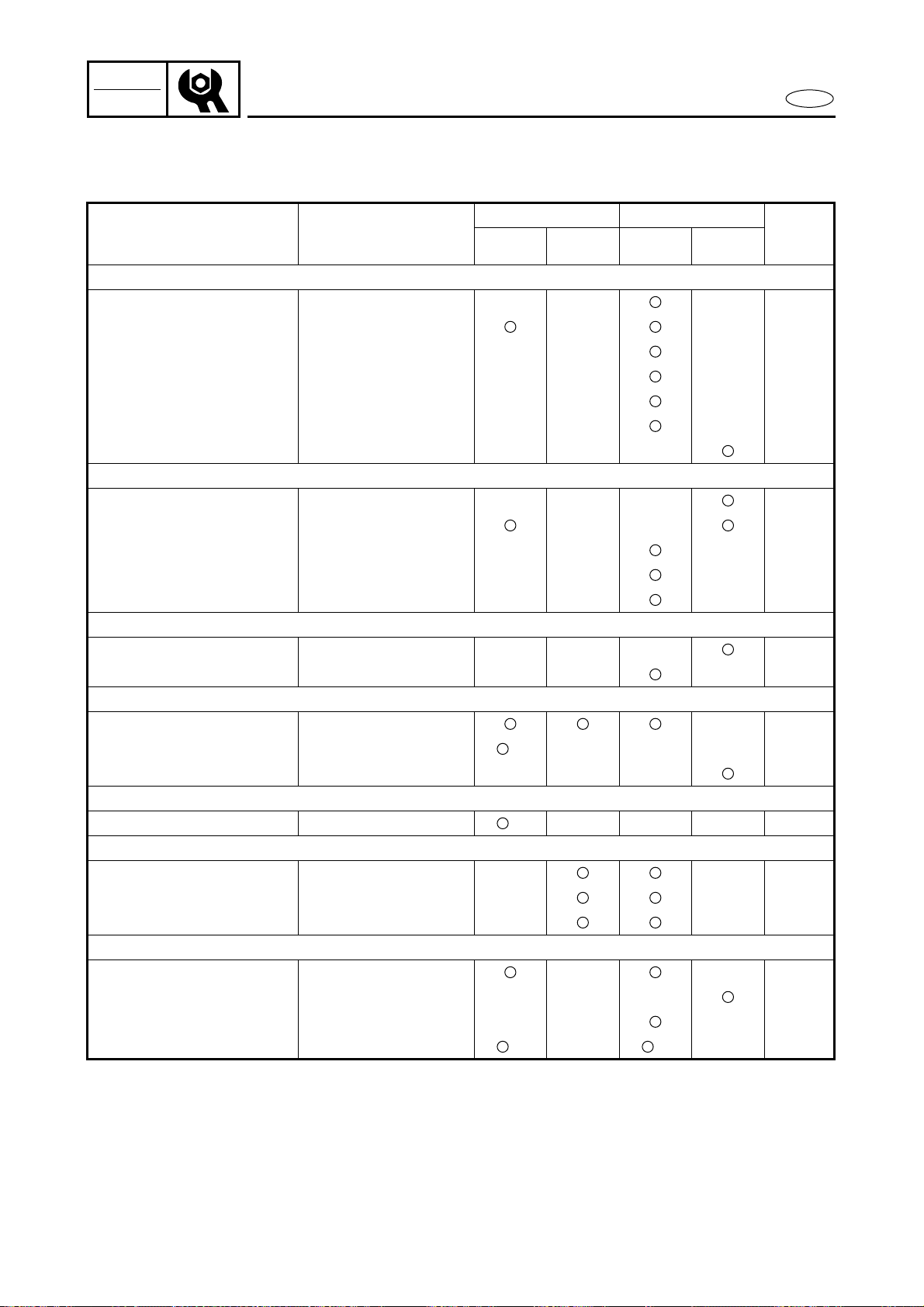
TIGHTENING TORQUES
SPECIFIED TORQUES
Part to tightened Part name
Thread
size
Q’ty
Tightening torque
Remarks
N•m kgf•m ft•lb
ENGINE UNIT
Engine unit – engine mount Bolt M8 4 17 1.7 12
572
LT
Exhaust chamber
assembly – muffler stay 1
– muffler stay 3
1st
Bolt M10 2
2 0.2 1.4
271
LT
4th 51 5.1 37
2nd
Bolt M10 4
2 0.2 1.4
6th 39 3.9 28
3rd
Nut M10 2
2 0.2 1.4
5th 51 5.1 37
7th
Bolt M10 1
2 0.2 1.4
9th 49 4.9 35
8th
Bolt M10 1
2 0.2 1.4
10th 49 4.9 35
Exhaust chamber –
muffler
1st
Nut M8 2
15 1.5 11
271
LT
2nd 39 3.9 28
1st
Bolt M8 3
15 1.5 11
2nd 33 3.3 24
1st
Nut M10 1
15 1.5 11
2nd 51 5.1 37
Exhaust chamber joint –
exhaust manifold
1st
Bolt M8 5
17 1.7 12
271
LT
2nd 34 3.4 24
Exhaust chamber joint –
muffler stay
1st
Bolt M10 1
2 0.2 1.4
271
LT
3rd 49 4.9 35
2nd
Bolt M8 2
2 0.2 1.4
271
LT
4th 37 3.7 27
Exhaust manifold –
cylinder
1st
Bolt M10 8
23 2.3 17
271
LT
2nd 51 5.1 37
Reed valve – reed valve seat Screw M3 16 0.8 0.08 0.58
242
LT
YPVS cable bracket – YPVS cover
– cylinder
Bolt M6 2 10 1.0 7.2
572
LT
YPVS cover – cylinder Bolt M6 6 10 1.0 7.2
572
LT
YPVS valve assembly – cylinder Bolt M5 2 4 0.4 2.9
271
LT
YPVS valve lever – shaft Bolt M4 2 3 0.3 2.2
242
LT
Spark plug – cylinder head Spark plug M14 2 25 2.5 18
Cylinder head – cylinder
1st
Bolt M8 10
15 1.5 11
572
LT
2nd 37 3.7 27
Cylinder – crankcase
1st
Bolt M10 8
22 2.2 16
572
LT
2nd 39 3.9 28
Starter motor lead – starter
motor
Nut M6 1 5 0.5 3.6
Flywheel magneto – crankshaft
assembly
Bolt M10 1 74 7.4 53
E
2-8
SPEC
E
TIGHTENING TORQUES
Drive coupling – crankshaft
assembly
Drive
coupling
M27 1 36 3.6 25
572
LT
Generator cover –
crankcase
1st
Bolt M8 8
15 1.5 11
271
LT
2nd 27 2.7 19
Pickup coil – generator cover Bolt M5 2 5 0.5 3.6
242
LT
Cable holder – generator cover Bolt M6 2 14 1.4 10
242
LT
Stator coil – generator cover Bolt M6 3 14 1.4 10
242
LT
Lower crankcase – upper
crankcase
1st
Bolt
M8 13
15 1.5 11
572
LT
2nd 27 2.7 19
M6 7 11 1.1 8.0
Mount bracket –
crankcase
1st
Bolt M8 6
15 1.5 11
271
LT
2nd 27 2.7 19
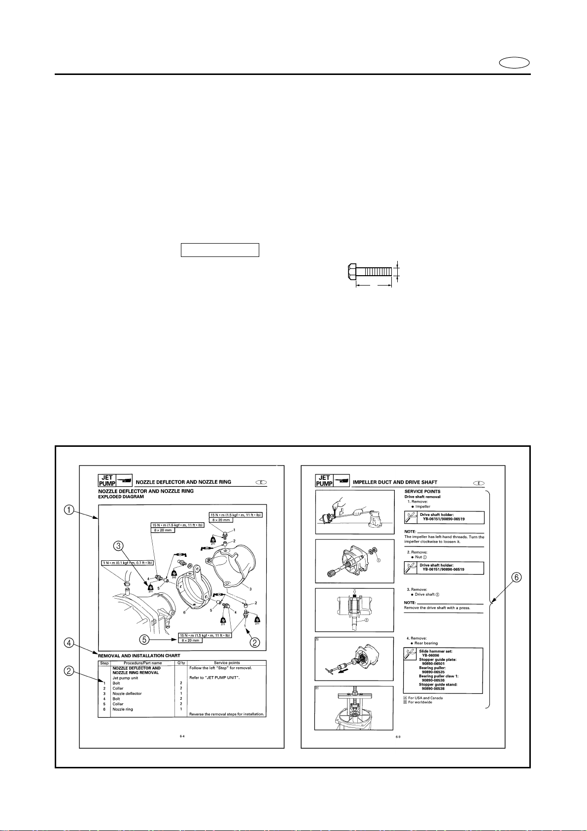
JET PUMP UNIT
Steering cable joint – nozzle
deflector
Nut M6 1 7 0.7 5.1
242
LT
Ride plate – hull Bolt M8 4 17 1.7 12
572
LT
Intake duct – hull Bolt M8 4 17 1.7 12
572
LT
Intake grate – hull Bolt M6 4 7 0.7 5.1
572
LT
Speed sensor – ride plate Screw M5 4 4 0.4 2.9
242
LT
Nozzle ring – nozzle Bolt M8 2 15 1.5 11
271
LT
Nozzle deflector – nozzle ring Bolt M8 2 15 1.5 11
271
LT
Water inlet cover – water inlet
strainer – impeller duct
Bolt M6 4 7 0.7 5.1
572
LT
Drive shaft nut – drive shaft Nut M16 1 74 7.4 53
Impeller (left-hand threads) –
drive shaft
Impeller M22 1 18 1.8 13
572
LT
Transom plate – hull Nut M10 4 26 2.6 19
Bilge strainer holder – bulkhead Screw M5 1 4 0.4 2.9
Intermediate housing – bulkhead Bolt M8 3 17 1.7 12
572
LT
Driven coupling – shaft
Driven
coupling
M27 1 36 3.6 25
572
LT
Grease nipple – intermediate
housing
Nipple — 1 5 0.5 3.6
572
LT
HULL AND HOOD
Handlebar cover – handlebar
cover stay
Screw M6 4 1.1 0.11 0.8
Handlebar cover stay – steering
column
Screw M6 4 2.9 0.29 2.1
Upper handlebar holder/lower
handle holder – steering column
Bolt M8 4 16 1.6 11
QSTS converter – hull Nut M6 2 5 0.5 3.6
QSTS cable 1, 2 locknut Nut M8 2 16 1.6 11
Throttle lever assembly –
handlebar
Screw M5 2 3 0.3 2.2
Part to tightened Part name
Thread
size
Q’ty
Tightening torque
Remarks
N•m kgf•m ft•lb
2-9
SPEC
E
TIGHTENING TORQUES
Handlebar switch assembly –
handlebar
Screw M5 2 3 0.3 2.2
QSTS grip assembly – handlebar Screw M6 1 3 0.3 2.2
Grip end – handlebar Bolt M5 2 1 0.1 0.7
Choke lever assembly –
handlebar
Screw M5 2 3 0.3 2.2
QSTS cable housing – cover Screw M4 1 1 0.1 0.7
Plate/steering column assembly
– deck
Nut M8 2 16 1.6 11
Steering column assembly – deck Nut M8 2 16 1.6 11
Steering arm – steering column Nut M8 1 16 1.6 11
Steering cable ball joint –
steering arm
Nut M6 1 5 0.5 3.6
Handlebar stopper – steering
column housing
Nut M10 1 26 2.6 19
QSTS cable locknut
(nozzle ring side)
Nut M5 1 3 0.3 2.2
QSTS cable – hull Nut — 1 6 0.6 4.3
QSTS cable end – pin – QSTS
converter
Nut M6 1 4 0.4 2.9
Steering cable locknut
(nozzle deflector side)
Nut M6 1 6 0.6 4.3
Steering cable – hull Nut — 1 6 0.6 4.3
Steering cable holder – bracket Bolt M6 1 6 0.6 4.3
Speed sensor lead – hull Nut — 1 6 0.6 4.3
Hinge assembly – front hood Bolt M6 2 12 1.2 8.7
Wind shield – front hood Screw M5 8 1 0.1 0.7
Hood lock – front hood Bolt M6 2 5 0.5 3.6
Hinge assembly – deck Nut M8 2 16 1.6 11
Steering console cover assembly
– deck
Nut M6 2 5 0.5 3.6
Bolt M6 4 3 0.3 2.2
Screw M5 2 2 0.2 1.4
Nut M8 2 16 1.6 11
Multifunction meter – holder Nut M5 2 2 0.2 1.4
Steering console cover – side
cover
Screw M6 4 3 0.3 2.2
Steering console cover – glove
compartment
Screw M5 4 1 0.1 0.7
Steering cable bracket – deck Bolt M6 1 6 0.6 4.3
Buzzer bracket – deck – steering
cable bracket
Bolt M6 2 6 0.6 4.3
Hood lock assembly – deck Nut M6 2 6 0.6 4.3
Seat lock assembly – seat Bolt M6 2 6 0.6 4.3
572
LT
Bracket/deck – notch Nut M10 1 26 2.6 19
Bracket/deck – hand grip Bolt M8 2 5 0.5 3.6
Part to tightened Part name
Thread
size
Q’ty
Tightening torque
Remarks
N•m kgf•m ft•lb
2-10
SPEC
E
TIGHTENING TORQUES
Hand grip – deck Nut M8 2 5 0.5 3.6
Seat bracket – deck Nut M8 2 15 1.5 11
Battery box/stay – holder Nut M6 2 9 0.9 6.5
Battery box – bracket/deck Nut M8 2 13 1.3 9.4
Battery box – electrical box Bolt M8 3 15 1.5 11
Extension bolt – battery negative
terminal
Bolt M6 1 6 0.6 4.3
Exhaust outlet – hull Bolt M6 3 6 0.6 4.3
Sponson – hull Bolt M8 6 18 1.8 13
Spout – hull Nut M24 1 5 0.5 3.6
Rope hole – hull Nut M24 2 5 0.5 3.6
Bow eye – hull Bolt M6 2 13 1.3 9.4
Flap – hull Bolt M6 8 6 0.6 4.3
Drain plug/packing – hull Nut M5 4 2 0.2 1.4
Engine mount – hull Bolt M8 8 17 1.7 12
572
LT
Engine damper – hull Bolt M6 2 6 0.6 4.3
Part to tightened Part name
Thread
size
Q’ty
Tightening torque
Remarks
N•m kgf•m ft•lb
GENERAL TORQUE
This chart specifies tightening torques for
standard fasteners with a standard ISO
thread pitch. Tightening torque specifica-
tions for special components or assemblies
are provided in applicable sections of this
manual. To avoid warpage, tighten multi-
fastener assemblies in a crisscross fashion
and progressive stages until the specified
tightening torque is reached. Unless other-
wise specified, tightening torque specifica-
tions require clean, dry threads.
Components should be at room tempera-
ture.
Nut A Bolt B
General torque
specifications
N•m kgf•m ft•lb
8 mm M5 5.0 0.5 3.6
10 mm M6 8.0 0.8 5.8
12 mm M8 18 1.8 13
14 mm M10 36 3.6 25
17 mm M12 43 4.3 31
2-11
SPEC
E
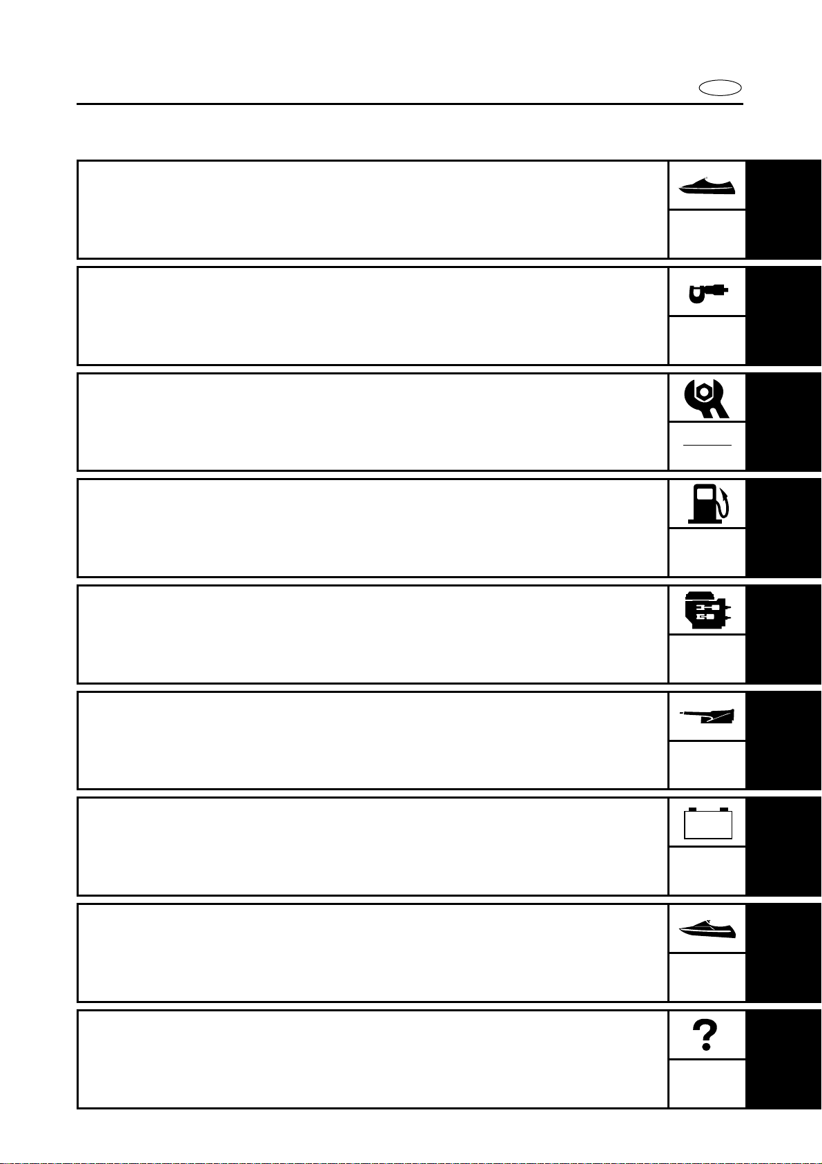
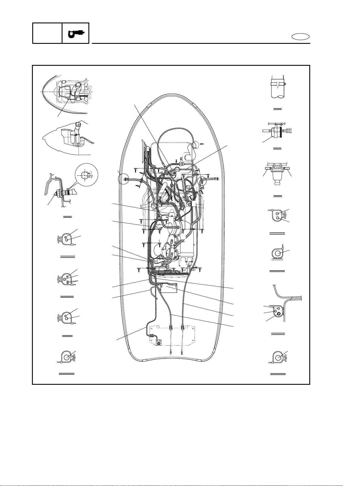
CABLE AND HOSE ROUTING
CABLE AND HOSE ROUTING
20˚
5
6
7
G-G
4
H-H
8
F-F
D-D
E-E
A
C
B
1
2
2
2
2
3
2
4
K-K
9
B
0
L
I-I
9
0
J-J
A
9
9
0
A
B
L
C
K
K
K
J
J
E
E
K
D
D
F
E
E
F
I I
H H
J J
GG
C
D
E
F
K
G
H
I
J
A
F
1 Fuel filter
2 Fuel tank breather hose
3 Fuel hose
4 Cooling water hose
5 Choke cable
6 Throttle cable
7 Oil return hose
8 Bilge hose
9 Speed sensor lead
0 Electrical box lead
A YPVS cables
B Cooling water pilot outlet
C Battery negative lead
D Battery
E Steering cable
F QSTS cable
G Battery breather hose
H Battery positive lead
I Starter motor lead
J Generator lead
K YPVS servomotor
2-12
SPEC
E
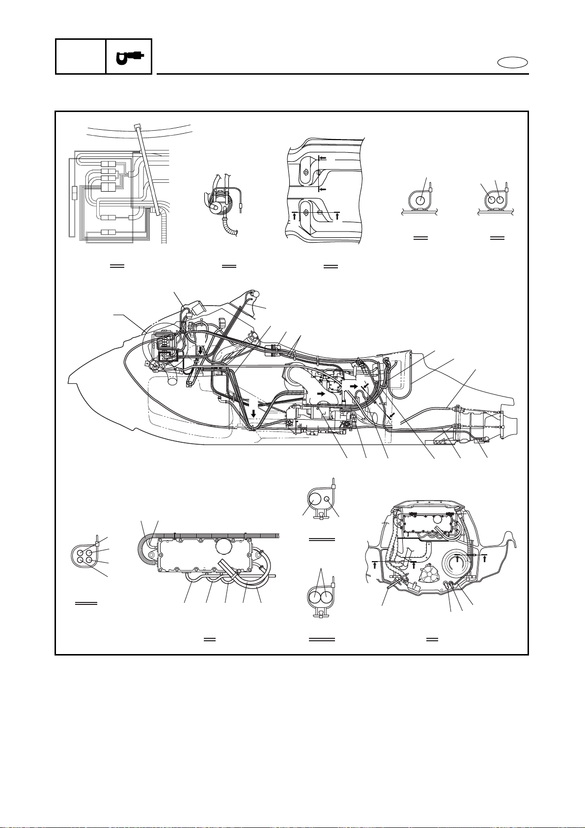
CABLE AND HOSE ROUTING
A
A
B
C
F
I
J
J
B
C
D E
J-J
G-G
4
8
H-H
I
F
9
F
F
G
A
A
E
E
0
1
2
3
E
E
B
C
D
7
6
5
4
G
G
H
H
H
K
I
J
2
5
L
M
4
G
E
F
A
7
D
D
1 Oil delivery hose
2 Fuel return hose
3 Fuel suction hose
4 Speed sensor lead
5 QSTS cable
6 Cooling water hose
7 Steering cable
8 Flushing hose
9 Bilge hoses
0 To multifunction meter
A To stator assembly
B To cylinder #1
C To cylinder #2
D To battery positive terminal
E To starter motor positive
terminal
F To thermoswitch
G Battery negative lead
H Buzzer lead
I Choke cable
J YPVS servomotor
K YPVS cables
L Battery positive lead
M Battery breather hose


E
1
2
3
4
5
6
7
8
9
INSP
ADJ
CHAPTER 3
PERIODIC INSPECTION AND ADJUSTMENT
MAINTENANCE INTERVAL CHART.............................................................. 3-1
PERIODIC SERVICE ........................................................................................ 3-2
CONTROL SYSTEM ................................................................................. 3-2
Steering column inspection ............................................................. 3-2
Steering cable inspection and adjustment ..................................... 3-2
Throttle cable inspection and adjustment ...................................... 3-3
Choke cable inspection and adjustment ......................................... 3-4
QSTS cable inspection and adjustment .......................................... 3-5
YPVS cable adjustment .................................................................... 3-6
FUEL SYSTEM.......................................................................................... 3-7
Fuel line inspection ........................................................................... 3-7
Trolling speed check and adjustment ............................................. 3-8
OIL INJECTION SYSTEM......................................................................... 3-9
Oil line inspection ............................................................................. 3-9
POWER UNIT............................................................................................ 3-9
Spark plug inspection ....................................................................... 3-9
ELECTRICAL ........................................................................................... 3-10
Battery inspection ........................................................................... 3-10
JET PUMP UNIT..................................................................................... 3-13
Impeller inspection ......................................................................... 3-13
Water inlet strainer inspection....................................................... 3-14
Bilge strainer inspection................................................................. 3-14
GENERAL................................................................................................ 3-14
Drain plug inspection...................................................................... 3-14
Lubrication points ........................................................................... 3-15
3-1
INSP
ADJ
E
MAINTENANCE INTERVAL CHART
MAINTENANCE INTERVAL CHART
The following chart should be considered strictly as a guide to general maintenance intervals.
Depending on operating conditions, the intervals of maintenance should be changed.
*1: After every ride
*2: Inspect fluid level before every ride
*3: Grease capacity 33.0–35.0 cm
3
(1.11–1.18 oz)
*4: Grease capacity 6.0–8.0 cm
3
(0.20–0.27 oz)
Item Remarks
Initial Every
Refer to
page
10 hours
(Break-in)
50 hours
(3 months)
100 hours
(6 months)
200 hours
(1 year)
CONTROL SYSTEM
Steering cable Inspect/adjust 3-2
Steering column Inspect 3-2
Throttle cable Inspect/adjust 3-3
Carburetor throttle shaft Inspect/adjust —
Choke cable Inspect/adjust 3-4
QSTS cable Inspect/adjust 3-5
YPVS cable Inspect/adjust 3-6
FUEL SYSTEM
Fuel tank Clean 4-9
Fuel filter Clean/replace 3-7
Fuel line Inspect 3-7
Trolling speed Check/adjust 3-8
Carburetor setting Inspect/adjust 4-18
OIL INJECTION SYSTEM
Oil injection system Check/clean 3-9
Oil pump cable Inspect/adjust 4-30
POWER UNIT
Spark plugs Inspect/clean/adjust 3-9
Cooling water passage Inspect/clean
*1
—
Rubber coupling Inspect —
ELECTRICAL
Battery Inspect
*2
3-10
JET PUMP UNIT
Impeller Inspect 3-13
Water inlet strainer Clean 3-14
Bilge strainer Clean 3-14
GENERAL
Bolts and nuts Retighten —
Drain plugs Inspect/replace 3-14
Lubrication points Grease 3-15
Intermediate housing Grease
*3
*4
3-17
3-2
INSP
ADJ
E
CONTROL SYSTEM
PERIODIC SERVICE
CONTROL SYSTEM
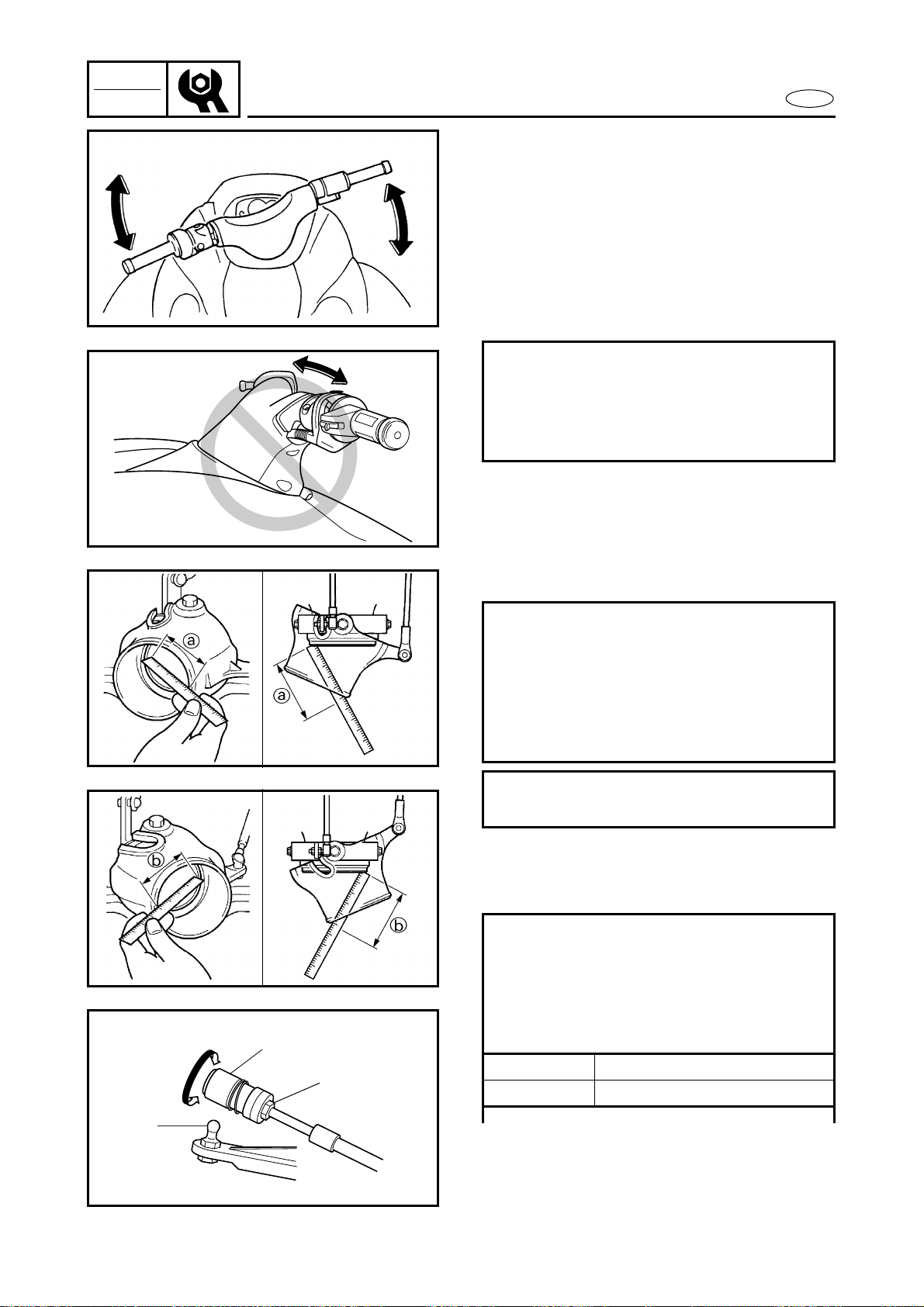
Steering column inspection
1. Inspect:
● Steering column
Excessive play → Replace the steer-
ing column.
Refer to “STEERING COLUMN” in
chapter 8.
Steering cable inspection and adjustment
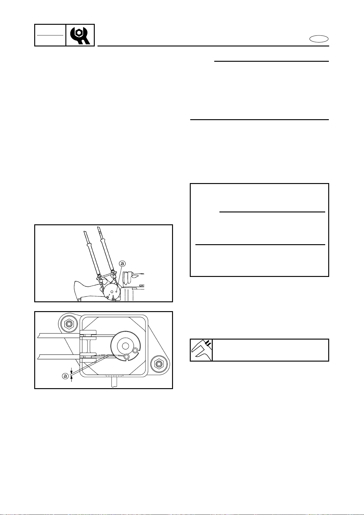
1. Inspect:
● Distance a, b (between the nozzle
and nozzle deflector)
Out of specification → Adjust.
2. Adjust:
● Steering cable joint
(steering column side)
Inspection steps:
● Move the handlebar up and down and
back and forth.
● Check the excessive play of the han-
dlebar.
Inspection steps:
● Set the control grip in the neutral posi-
tion.
● Turn the handlebar from lock to lock.
● Measure distances a and b.
● If the difference is not within specifica-
tion, adjust the cable joint.
Difference of distances a and b:
Maximum 5 mm (0.2 in)
Adjustment steps:
● Loosen the locknut 1.
● Disconnect the steering cable joint 2
from the ball joint 3.
● Turn the cable joint in or out for adjust-
ing the distances a and b.
Turn in Distance a is increased.
Turn out Distance b is increased.
1
2
3
3-3
INSP
ADJ
E
CONTROL SYSTEM
NOTE:
If the steering cable cannot be properly
adjusted at the steering column side, make
sure the steering cable at the jet pump side
is set to the specified length. Refer to
“REMOTE CONTROL CABLES AND SPEED
SENSOR LEAD” in chapter 8.
Throttle cable inspection and adjustment
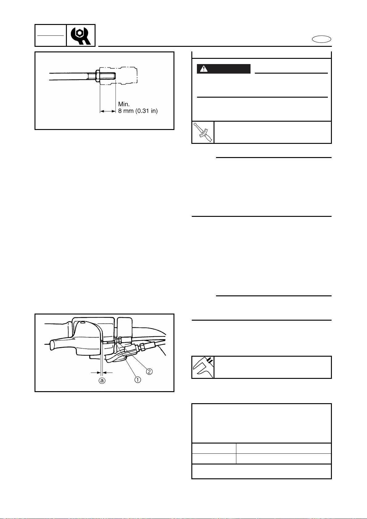
NOTE:
Before adjusting the throttle lever free play,
adjust the trolling speed.
1. Measure:
● Throttle lever free play a
Out of specification → Adjust.
2. Adjust:
● Throttle lever free play
WARNING
The cable joint must be screwed in more
than 8 mm (0.31 in).
● Connect the cable joint and tighten the
locknut.
T
R
.
.
Locknut:
6 N • m (0.6 kgf • m, 4.3 ft • lb)
Throttle lever free play:
4–7 mm (0.16–0.28 in)
Adjustment steps:
● Loosen the locknut 1.
● Turn the adjuster 2 in or out until the
specified free play is obtained.
Turn in Free play is increased.
Turn out Free play is decreased.
● Tighten the locknut.
3-4
INSP
ADJ
E
CONTROL SYSTEM
WARNING
After adjusting the free play, turn the han-
dlebar to the right and left and make sure
that the trolling speed does not increase.
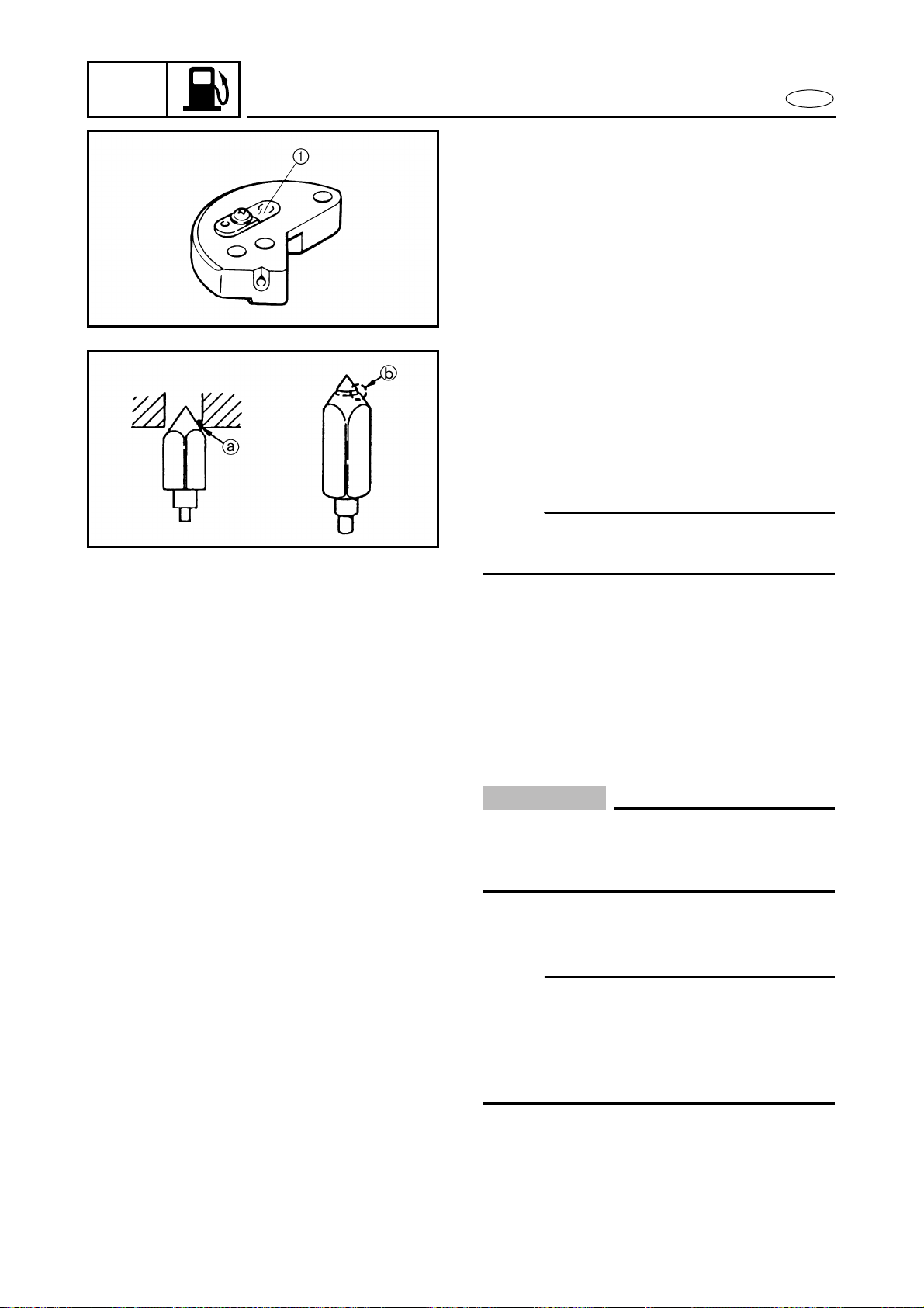
Choke cable inspection and adjustment
1. Check:
● Choke lever operation
Incorrect operation → Adjust.
2. Adjust:
● Choke lever operation
Checking steps:
● Check that the choke lever moves back
slightly when it is fully opened.
● Check that the inner cable has some
slack when the choke lever is com-
pletely closed.
Adjustment steps:
● Loosen the locknut 1.
● Screw the adjuster 2 fully into the
bracket.
● Align the choke lever end a within the
line marks b.
● Turn out the adjuster 2 until the inner
cable is taut.
NOTE:
If the inner cable is difficult to make taut
using the adjuster 2, adjust the choke
lever so that the cable is taut. The cable
must be taut when the choke lever end
a is positioned within the line marks b.
Reset the adjuster if necessary.
● Tighten the locknut 1.
3-5
INSP
ADJ
E
CONTROL SYSTEM
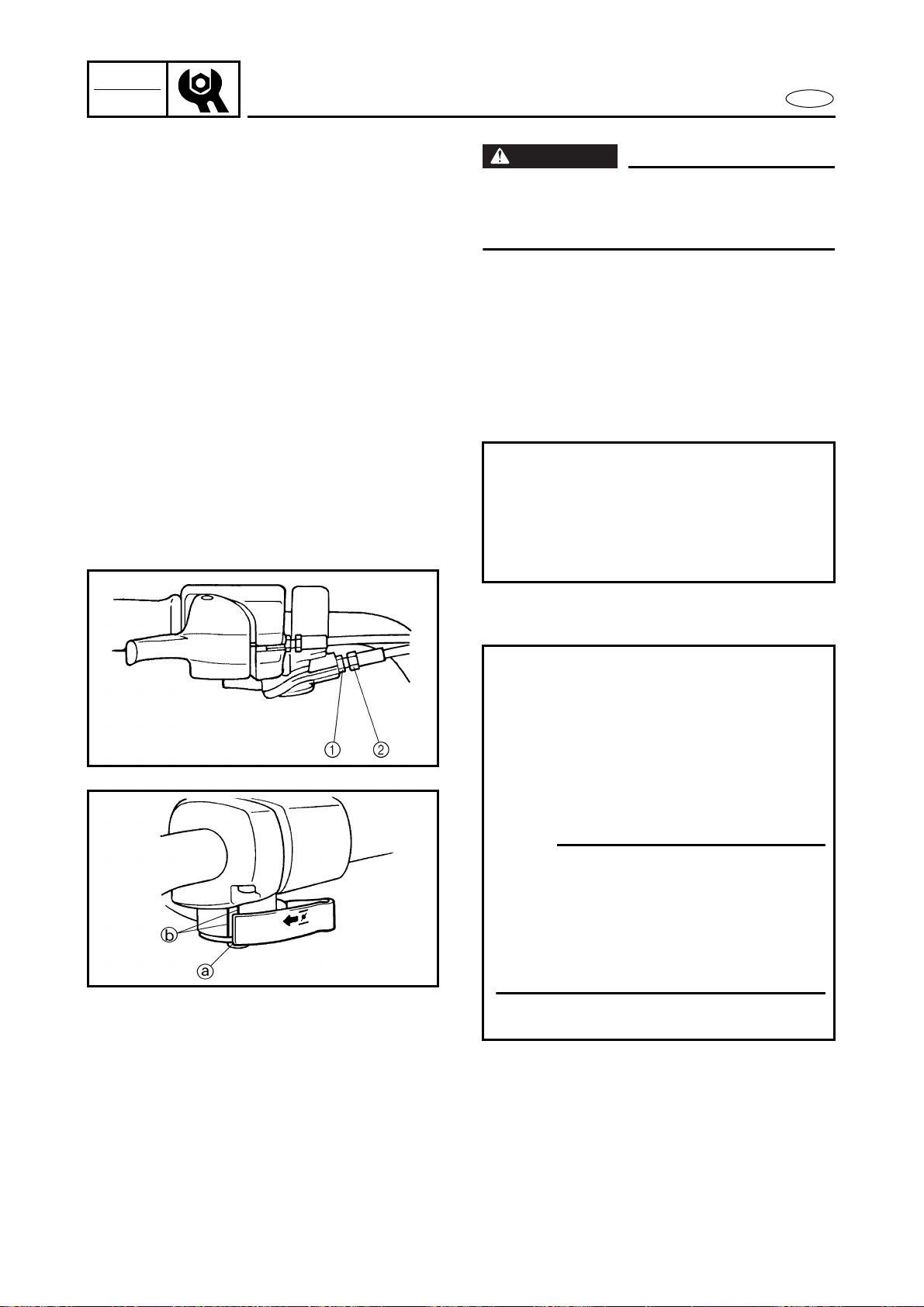
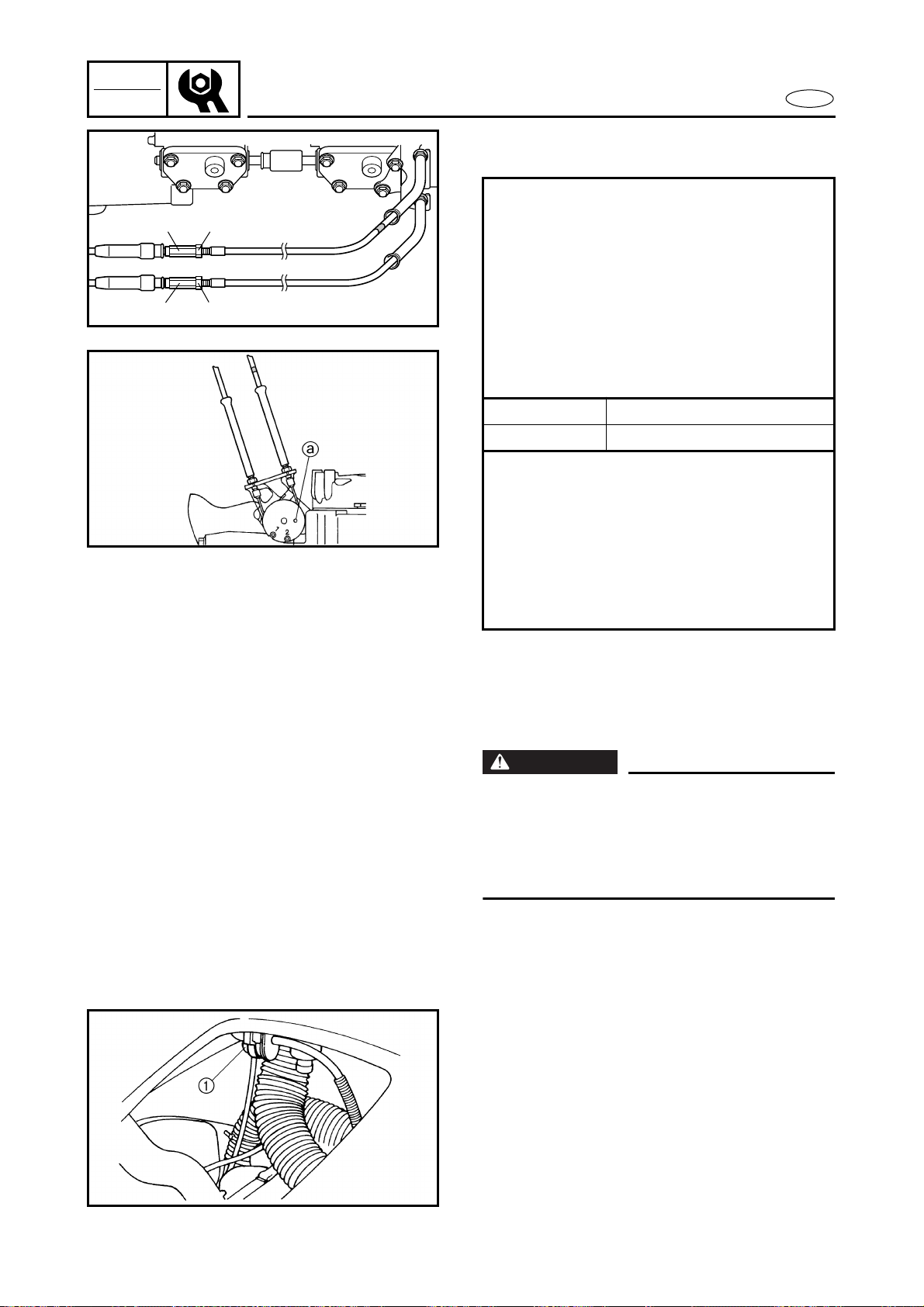
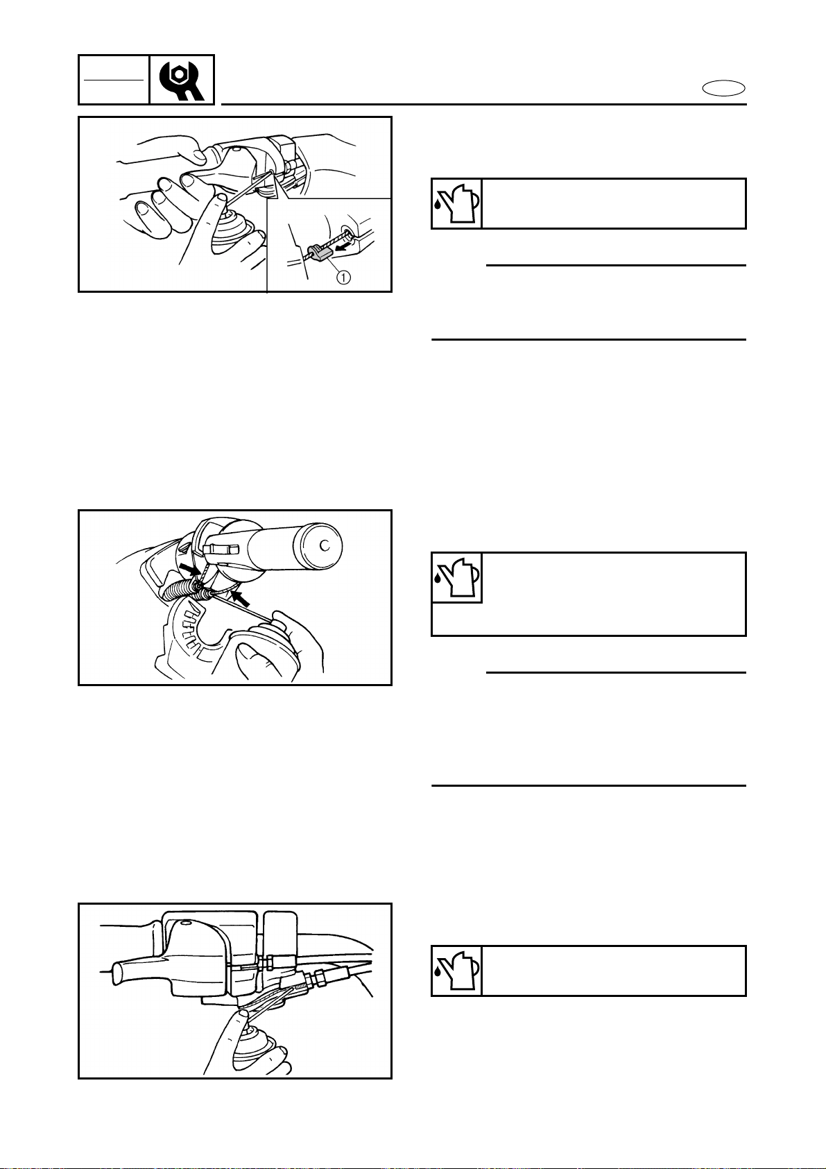
QSTS cable inspection and adjustment
1. Measure:
● Nozzle deflector set length a, b
Difference → Adjust.
Measurement steps:
● Set the control grip in the neutral posi-
tion.
● Measure the nozzle deflector set
length a and b.
● If a and b length are not even, adjust
the cable joint.
2. Adjust:
● QSTS cable
Adjustment steps:
● Set the control grip in the neutral posi-
tion.
● Loosen the locknut 1.
● Remove the nut 2 and pivot pin 3.
● Set the nozzle deflector in the center
position.
● Turn the cable joint 4 for adjusting.
Turn in Length b is increased.
Turn out Length a is increased.
WARNING
The cable joint must be screwed in more
than 8 mm (0.31 in).
● Connect the cable joint 4 and pivot
pin 3 and tighten the nut 2.
T
R
.
.
Nut:
4 N • m (0.4 kgf • m, 2.9 ft • lb)
● Tighten the locknut 1.
T
R
.
.
Locknut:
4 N • m (0.4 kgf • m, 2.9 ft • lb)
3-6
INSP
ADJ
E
CONTROL SYSTEM
NOTE:
If the QSTS cable cannot be properly
adjusted at the QSTS converter side, make
sure the QSTS cable at the jet pump side is
set to the specified length.
Refer to “REMOTE CONTROL CABLES AND
SPEED SENSOR LEAD” in chapter 8.
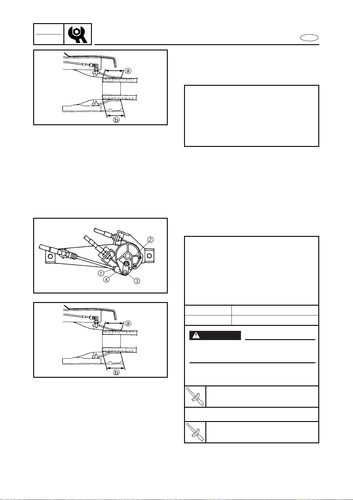
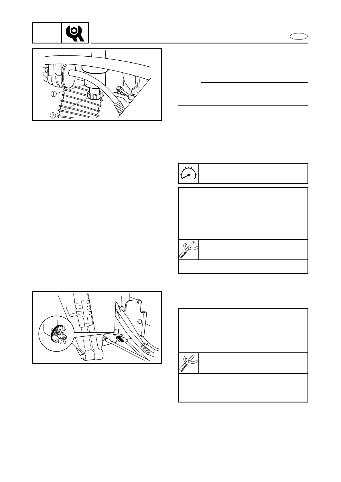
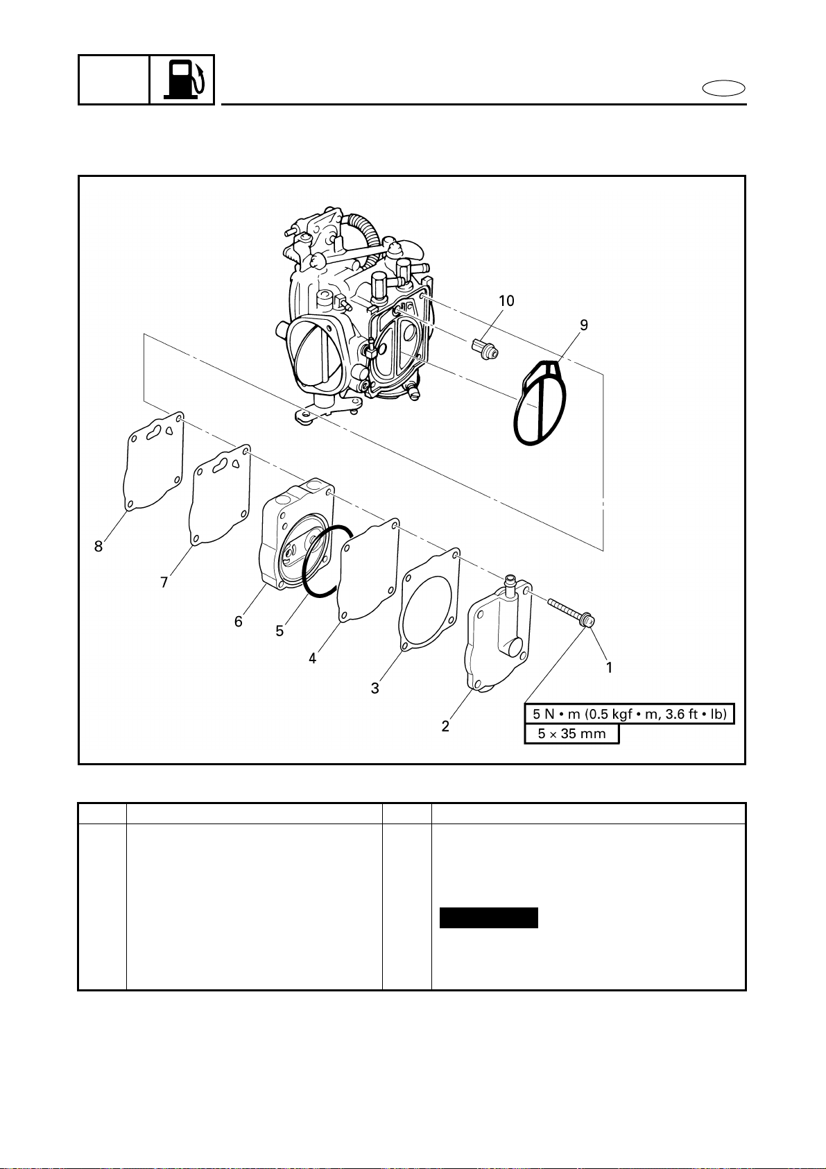
YPVS cable adjustment
1. Check:
● YPVS valve position
Incorrect position → Adjust the YPVS
cable.
Checking steps:
● Start the engine and then stop it.
NOTE:
When the engine has been stopped for 3
seconds, the YPVS valve assembly will
retract and extend one time.
● Check that the hole a in the pulley is
aligned with the hole in the cylinder
when the YPVS valve is fully closed.
2. Measure:
● YPVS cable slack a
Out of specification → Adjust.
YPVS cable slack:
0.5–1.5 mm (0.02–0.06 in)
3-7
INSP
ADJ
E
CONTROL SYSTEM/FUEL SYSTEM
3. Adjust:
● YPVS cables 1 and 2
FUEL SYSTEM
WARNING
● Stop the engine, set the fuel cock to
“OFF” before servicing the fuel system.
● When removing fuel system parts, wrap
them in a cloth and take care that no fuel
spills into the engine compartment.
Fuel line inspection
1. Inspect:
● Fuel filter 1
Contaminants → Replace.
Cracks/damage → Replace.
Water contamination → Replace and
check the fuel tank.
● Fuel hoses
● Fuel tank
● Fuel hoses through part
● Fuel filler cap
Cracks/damage → Replace.
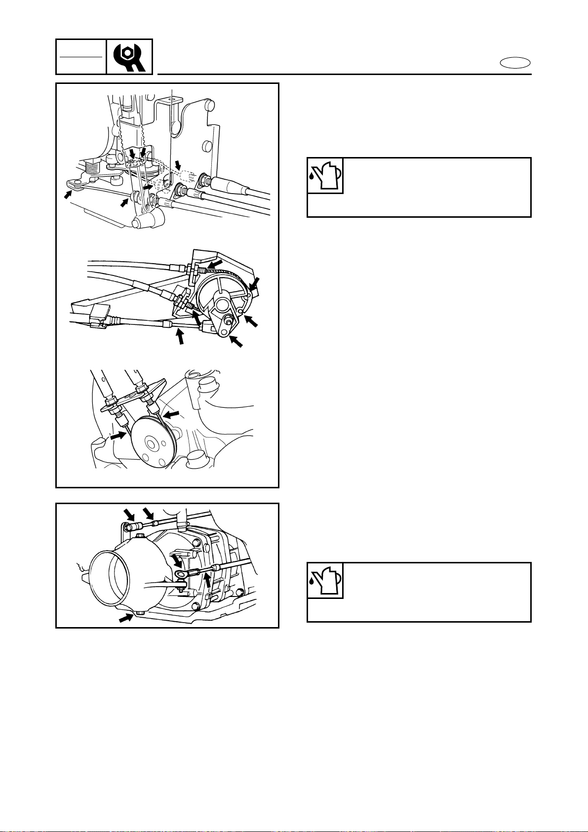
Adjustment steps:
● Loosen locknuts 1 and 2.
● Turn in adjusters 3 and 4 until there
is slack in the cables.
● Align the hole a in the pulley with the
hole in the cylinder.
● Insert a 4-mm-diameter pin through
the holes in the pulley and cylinder.
● Turn adjusters 3 and 4 in or out until
the specified slack is obtained.
Turn in Slack is increased.
Turn out Slack is decreased.
● Finger tighten locknuts 1 and 2.
● Remove the pin.
● Start and stop the engine.
● Recheck the hole alignment.
● If the hole alignment is correctly,
tighten the locknuts.
● If the hole alignment is incorrect,
repeat the above steps.
41
3
2
3-8
INSP
ADJ
E
FUEL SYSTEM
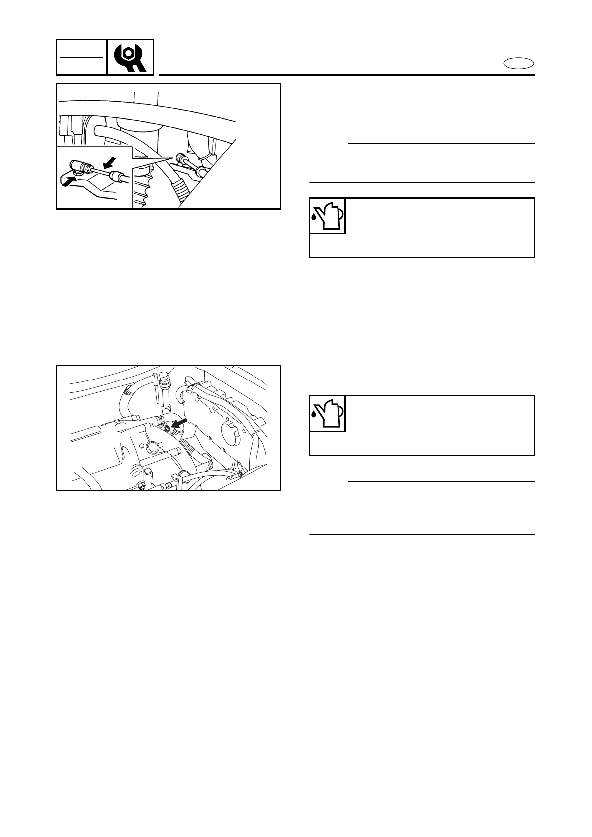
2. Inspect:
● Water separator 1
Water accumulation → Drain.
NOTE:
If need the water draining, remove the drain
plug 2.
Trolling speed check and adjustment
1. Check:
● Trolling speed
Out of specification → Adjust.
Trolling speed:
1,300 ± 50 r/min
Checking steps (with the watercraft in
the water):
● Start the engine and allow it to warm
up for several minutes.
● Attach the engine tachometer to the
spark plug lead.
Engine tachometer:
YU-8036-A/90890-06760
● Measure the engine trolling speed.
2. Adjust:
● Trolling speed
Adjustment steps:
● Start the engine and allow it to warm
up for several minutes.
● Attach the engine tachometer to the
spark plug lead.
Engine tachometer:
YU-8036-A/90890-06760
● Turn the throttle stop screw 1 in or
out until the specified trolling speed is
obtain.
1
3-9
INSP
ADJ
E
OIL INJECTION SYSTEM/POWER UNIT
OIL INJECTION SYSTEM
Oil line inspection
1. Inspect:
● Oil filter
Contaminants → Clean.
Frays/tears → Replace.
● Rubber seal
Cracks/wear → Replace.
● Oil hoses
● Oil tank
● Oil filler cap
Cracks/damage → Replace.
● Check valve
Malfunction → Replace.
CAUTION:
Do not allow the oil tank to become com-
pletely empty. If the oil tank becomes
empty the oil injection pump must be bled
to ensure proper oil flow, otherwise engine
damage may occur. Refer to “OIL PUMP” in
chapter 4.
POWER UNIT
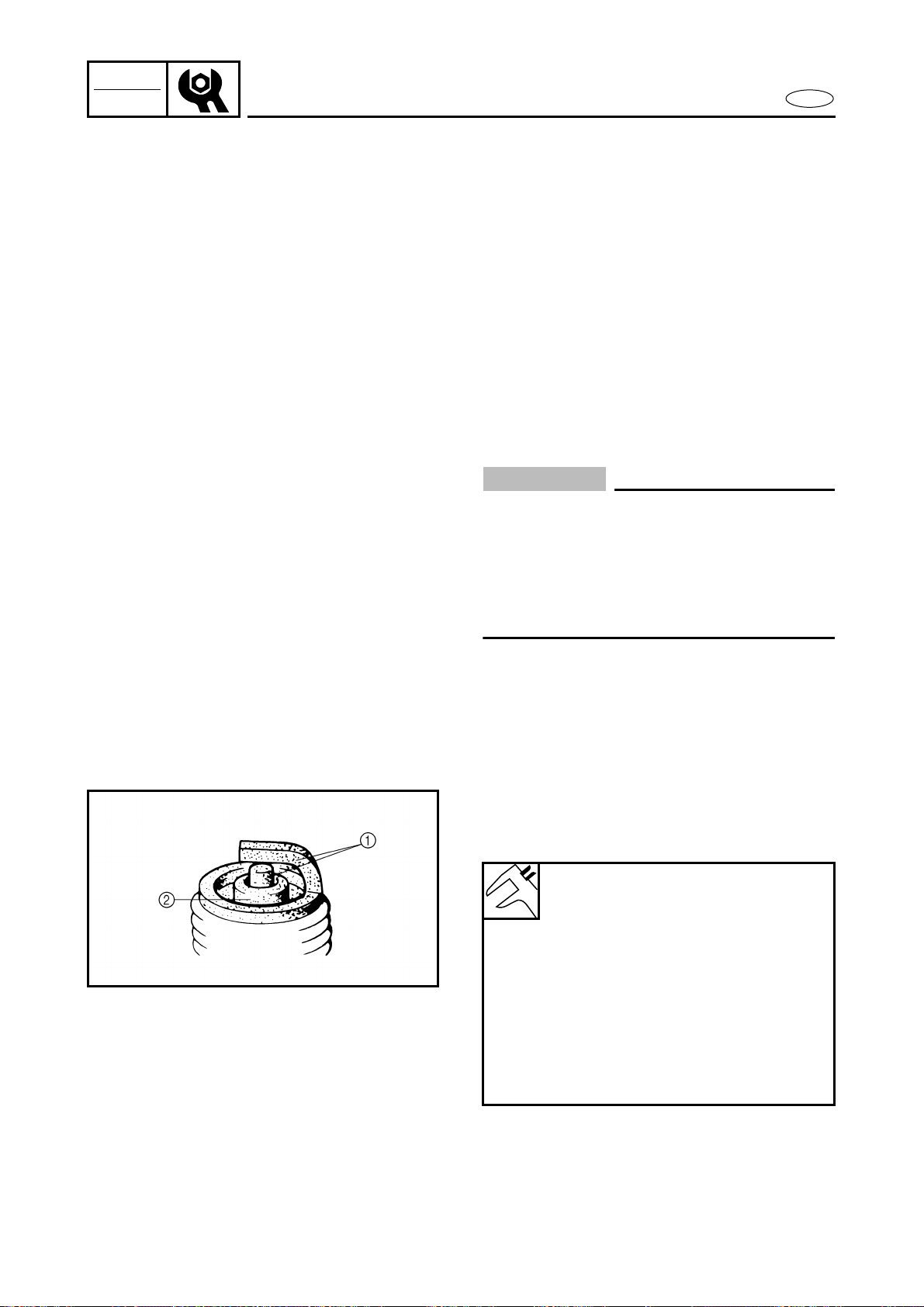
Spark plug inspection
1. Inspect:
● Electrodes 1
Damage/wear → Replace.
● Insulator color 2
Distinctly different color → Check the
engine condition.
2. Clean:
● Spark plug
(with a spark plug cleaner or wire
brush)
Color guide:
Medium to light tan color:
Normal
Whitish color:
Lean fuel mixture
Air leak
Incorrect settings
Blackish color:
Overly rich mixture
Electrical malfunction
Excessive oil use
Defective spark plug
3-10
INSP
ADJ
E
POWER UNIT/ELECTRICAL
3. Measure:
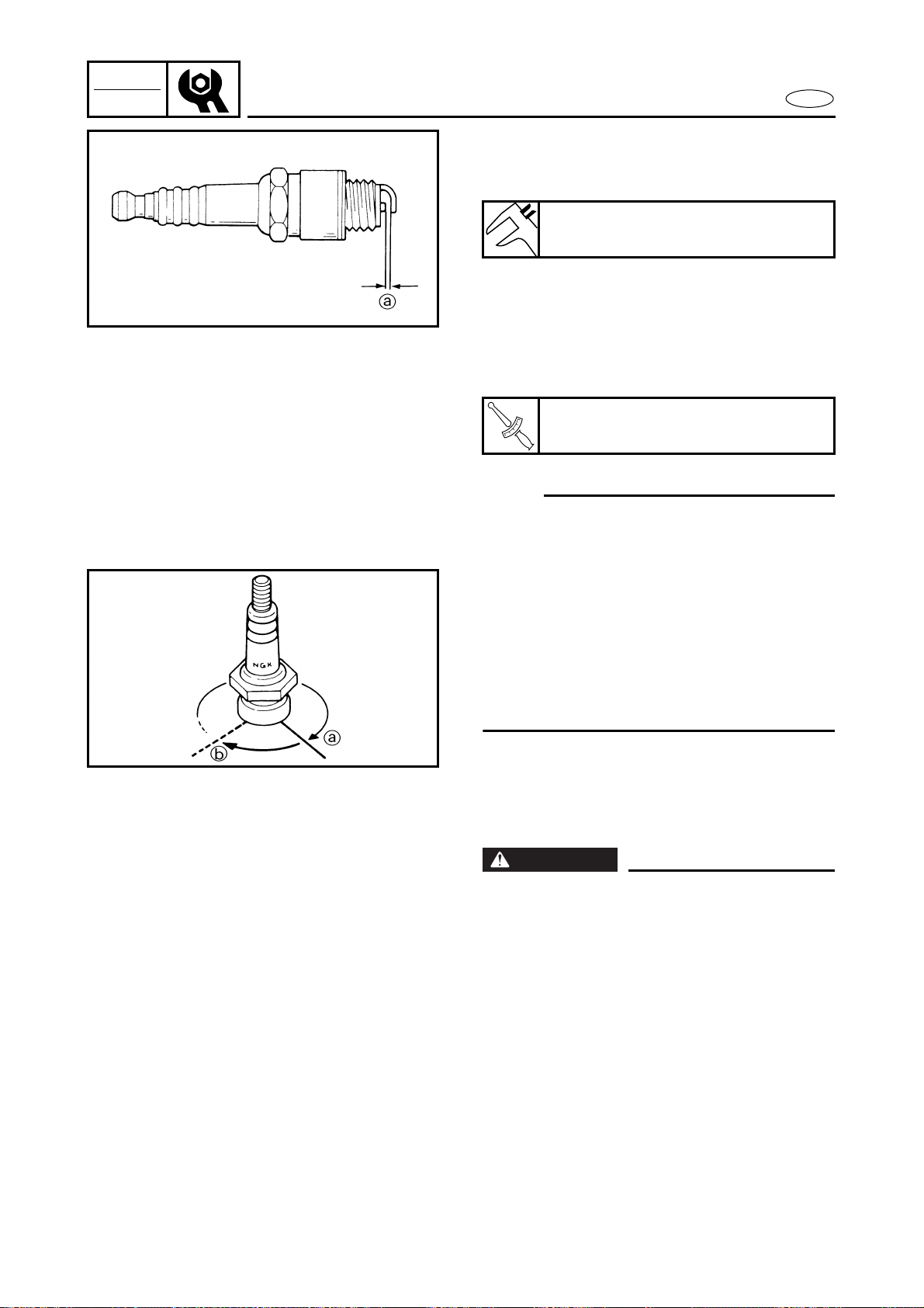
● Spark plug gap a
Out of specification → Regap.
Spark plug gap:
0.7–0.8 mm (0.028–0.031 in)
4. Tighten:
● Spark plug
NOTE:
● Before installing the spark plug, clean the
gasket surface and spark plug surface.
Also, it is suggested to apply a thin film of
anti-seize compound to the spark plug
threads to prevent thread seizure.
● If a torque wrench is not available, a good
estimate of the correct tightening torque
for a new spark plug is to finger tighten a
the spark plug and then tighten it another
1/4 to 1/2 of a turn b.
T
R
.
.
Spark plug:
25 N • m (2.5 kgf • m, 18 ft • lb)
ELECTRICAL
Battery inspection
WARNING
Battery electrolyte is dangerous; it contains
sulfuric acid which is poisonous and highly
caustic.
Always follow these preventive measures:
● Avoid bodily contact with electrolyte as it
can cause severe burns or permanent eye
injury.
● Wear protective eye gear when handling
or working near batteries.
Antidote (EXTERNAL):
● SKIN - Wash with water.
● EYES - Flush with water for 15 minutes
and get immediate medical attention.
3-11
INSP
ADJ
E
ELECTRICAL
Antidote (INTERNAL):
● Drink large quantities of water or milk fol-
lowed with milk of magnesia, beaten egg
or vegetable oil. Get immediate medical
attention.
Batteries generate explosive, hydrogen
gas. Always follow these preventive mea-
sures:
● Charge batteries in a well-ventilated area.
● Keep batteries away from fire, sparks or
open flames (e.g., welding equipment,
lighted cigarettes).
● DO NOT SMOKE when charging or han-
dling batteries.
KEEP BATTERIES AND ELECTROLYTE OUT
OF REACH OF CHILDREN.
CAUTION:
● Do not place the battery on its side.
● Before adding electrolyte or recharging,
be sure to remove the battery from the
battery box.
● Make sure that the battery breather hose
is properly connected and is not pinched
or damaged.
1. Remove:
● Band
● Battery negative lead 1
● Battery positive lead 2
● Battery
● Battery breather hose 3
WARNING
● When removing the battery, disconnect
the negative lead first.
● Remove the battery to prevent acid loss
during turning the machine on its side for
the impeller service.
3-12
INSP
ADJ
E
ELECTRICAL
2. Inspect:
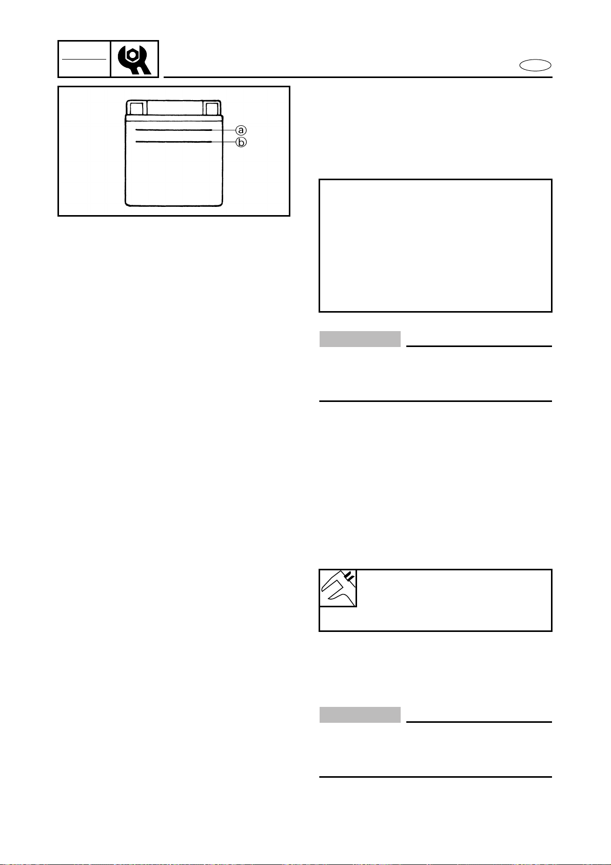
● Electrolyte level
Low → Add distilled water.
The electrolyte level should be
between the upper a and lower b
level marks.
CAUTION:
Use only distilled water. Other types of
water contain minerals which are harmful
to batteries.
Filling steps:
● Remove each filler cap.
● Add distilled water.
● When the electrolyte level reaches the
upper level mark, allow the cell to
stand for 20 minutes. If the electrolyte
level drops, add more distilled water
so the level reaches the upper level
mark.
3. Inspect:
● Specific gravity
Out of specification → Charge.
Specific gravity at 20 ˚C (68 ˚F):
1.28
Charging current:
1.9 amps × 10 hrs (68.4 kC)
4. Install:
● Filler caps
CAUTION:
Before installation, rinse off any fluid from
the battery box and battery and make sure
that the battery is dry before installing it.
3-13
INSP
ADJ
E
ELECTRICAL/JET PUMP UNIT
5. Install:
● Battery breather hose 1
● Battery
● Battery positive lead 2
● Battery negative lead 3 (with termi-
nal extension at battery negative ter-
minal)
● Band
CAUTION:
● Connect the positive lead to the battery
terminal first.
● Make sure the battery leads are con-
nected properly. Reversing the leads can
seriously damage the electrical system.
● Make sure that the battery breather hose is
properly connected and is not obstructed.
● Coat the terminals with a water resistant
grease to minimize terminal corrosion.
JET PUMP UNIT
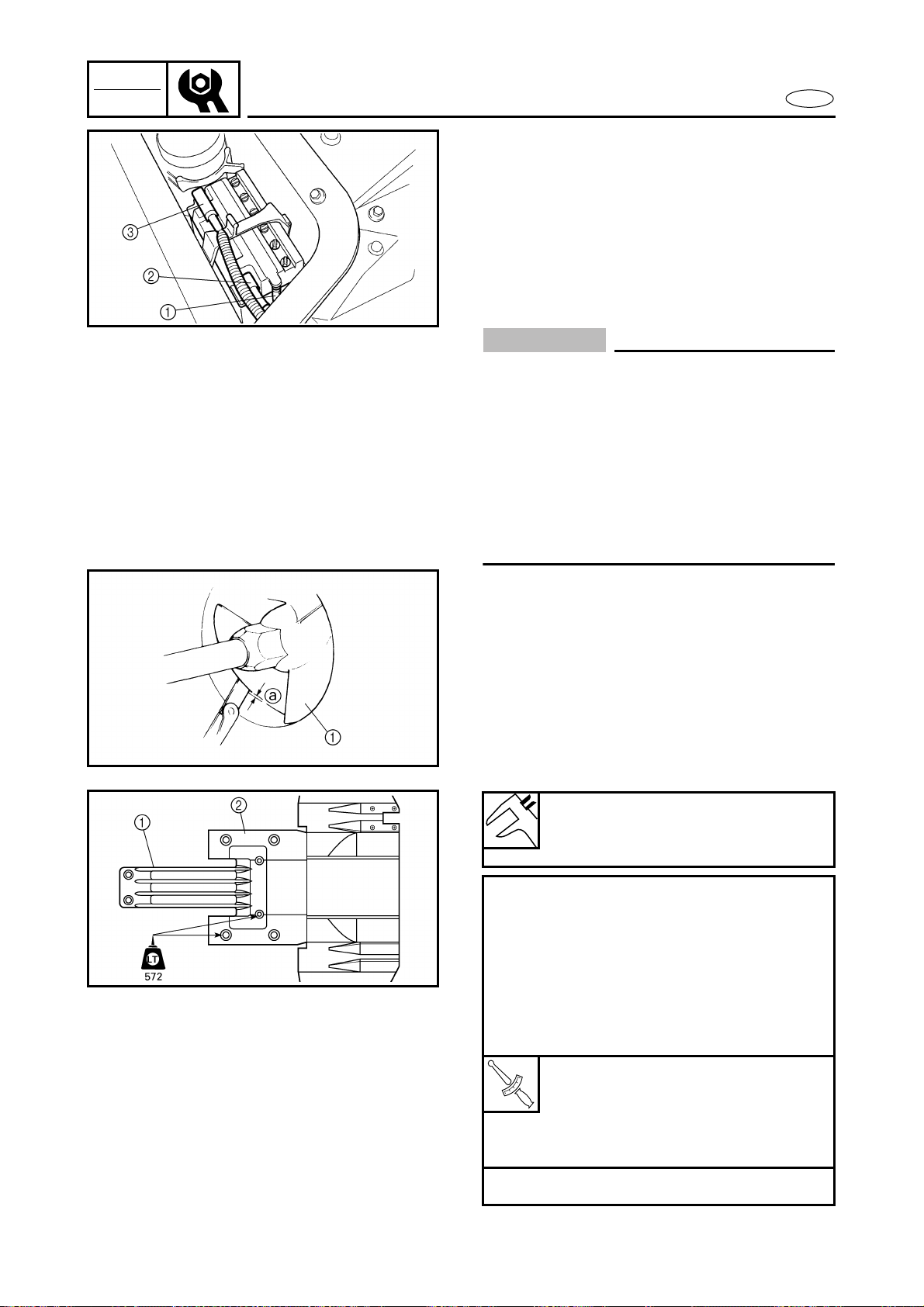
Impeller inspection
1. Check:
● Impeller 1
Damage/wear → Replace.
Nicks/scratches → File or grind.
2. Measure:
● Impeller-to-housing clearance a
Out of specification → Replace.
Max. impeller-to-housing
clearance:
0.6 mm (0.02 in)
Measurement steps:
● Remove the battery leads.
● Remove the intake grate 1 and intake
duct 2.
● Measure the clearance at each impel-
ler blade as shown (a total of three
measurements).
● Install the intake grate and intake duct.
T
R
.
.
Bolt:
M6: 7 N • m
(0.7 kgf • m, 5.1 ft • lb)
M8: 17 N • m
(1.7 kgf • m, 12 ft • lb)
● Install the battery leads.
3-14
INSP
ADJ
E
JET PUMP UNIT/GENERAL
Water inlet strainer inspection
1. Inspect:
● Water inlet strainer
Contaminants → Clean.
Cracks/damage → Replace.
Inspection steps:
● Remove the water inlet cover 1.
● Inspect the water inlet strainer mesh
a.
● Install the water inlet cover.
1
a
Bilge strainer inspection
1. Inspect:
● Bilge strainer
Contaminants → Clean.
Cracks/damage → Replace.
Inspection steps:
● Disconnect the bilge strainer 1 from
the bilge strainer holder.
● Inspect the bilge strainer.
1
GENERAL
Drain plug inspection
1. Inspect:
● Drain plugs
Cracks/damage → Replace.
● O-rings
Cracks/wear → Replace.
● Screw threads
Contaminants → Clean.
3-15
INSP
ADJ
E
GENERAL
Lubrication points
1. Lubricate:
● Throttle cable (handlebar side)
NOTE:
Before lubricating the throttle cable,
squeeze the throttle lever and remove the
rubber seal 1.
Recommended lubricant:
Rust inhibitor
2. Lubricate:
● QSTS control cables (handlebar side)
NOTE:
Before lubricating the QSTS control cables,
remove the QSTS cable housing cover.
Spray the rust inhibitor into the outer
cables, and apply grease to the inner
cables.
Recommended lubricant:
Yamaha marine grease,
Yamaha grease A
(Water resistant grease)
3. Lubricate:
● Choke cable (handlebar side)
Recommended lubricant:
Rust inhibitor
3-16
INSP
ADJ
E
GENERAL
4. Lubricate:
● Throttle cable (carburetor side)
● Oil pump cable
● QSTS cables (pulley side)
● YPVS cables
Recommended grease:
Yamaha marine grease,
Yamaha grease A
(Water resistant grease)
5. Lubricate:
● Nozzle pivot shaft
● Steering cable (nozzle side)
● QSTS cable (nozzle side)
Recommended grease:
Yamaha marine grease,
Yamaha grease A
(Water resistant grease)
3-17
INSP
ADJ
E
GENERAL
6. Lubricate:
● Steering cable
● Steering cable joint
NOTE:
Disconnect the joints and apply a small
amount of grease.
Recommended grease:
Yamaha marine grease,
Yamaha grease A
(Water resistant grease)
7. Fill:
● Intermediate housing
NOTE:
Fill the intermediate housing with the rec-
ommended grease through the grease nip-
ples.
Recommended grease:
Yamaha marine grease,
Yamaha grease A
(Water resistant grease)


E
FUEL
CHAPTER 4
FUEL SYSTEM
FUEL COCK AND FUEL FILTER ..................................................................... 4-1
EXPLODED DIAGRAM............................................................................. 4-1
REMOVAL AND INSTALLATION CHART ............................................... 4-1
SERVICE POINTS ..................................................................................... 4-2
Fuel filter inspection ......................................................................... 4-2
Fuel cock inspection.......................................................................... 4-2
OIL TANK ........................................................................................................ 4-3
EXPLODED DIAGRAM............................................................................. 4-3
REMOVAL AND INSTALLATION CHART ............................................... 4-3
SERVICE POINTS ..................................................................................... 4-5
Oil line inspection ............................................................................. 4-5
Oil level sensor inspection ............................................................... 4-5
Oil tank inspection ............................................................................ 4-5
FUEL TANK ..................................................................................................... 4-6
EXPLODED DIAGRAM............................................................................. 4-6
REMOVAL AND INSTALLATION CHART ............................................... 4-6
SERVICE POINTS ..................................................................................... 4-9
Check valve inspection ..................................................................... 4-9
Fuel level sensor inspection............................................................. 4-9
Fuel tank inspection .......................................................................... 4-9
Pipe joint inspection ......................................................................... 4-9
INTAKE SILENCER ....................................................................................... 4-10
EXPLODED DIAGRAM........................................................................... 4-10
REMOVAL AND INSTALLATION CHART ............................................. 4-10
CARBURETOR UNIT..................................................................................... 4-11
EXPLODED DIAGRAM........................................................................... 4-11
REMOVAL AND INSTALLATION CHART ............................................. 4-11
SERVICE POINTS ................................................................................... 4-18
Throttle valve synchronization inspection and adjustment ........ 4-18
Choke cable and throttle cable installation................................... 4-19
Oil pump cable installation ............................................................ 4-19
Carburetor assembly ...................................................................... 4-19

E
1
2
3
4
5
6
7
8
9
FUEL
CARBURETOR .............................................................................................. 4-20
EXPLODED DIAGRAM........................................................................... 4-20
REMOVAL AND INSTALLATION CHART ............................................. 4-20
SERVICE POINTS ................................................................................... 4-23
Diaphragm inspection .................................................................... 4-23
Accelerator pump body inspection ............................................... 4-23
Arm inspection ................................................................................ 4-23
Regulator body inspection ............................................................. 4-24
Needle valve inspection ................................................................. 4-24
Jet and carburetor body inspection .............................................. 4-24
Carburetor assembly ...................................................................... 4-24
FUEL PUMP .................................................................................................. 4-25
EXPLODED DIAGRAM........................................................................... 4-25
REMOVAL AND INSTALLATION CHART ............................................. 4-25
SERVICE POINTS ................................................................................... 4-27
Fuel pump inspection ..................................................................... 4-27
Fuel filter inspection ....................................................................... 4-27
OIL PUMP...................................................................................................... 4-28
EXPLODED DIAGRAM........................................................................... 4-28
REMOVAL AND INSTALLATION CHART ............................................. 4-28
SERVICE POINTS ................................................................................... 4-30
Oil pump inspection........................................................................ 4-30
Oil hose inspection ......................................................................... 4-30
Check valve inspection ................................................................... 4-30
Oil pump cable adjustment ............................................................ 4-30
Oil injection pump air bleeding ..................................................... 4-31
4-1
FUEL
E
FUEL COCK AND FUEL FILTER
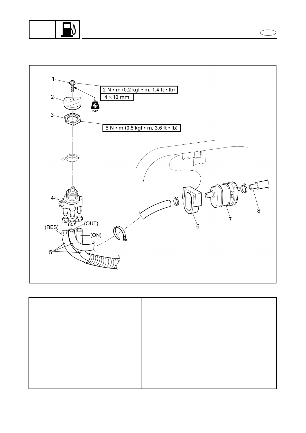
FUEL COCK AND FUEL FILTER
EXPLODED DIAGRAM
REMOVAL AND INSTALLATION CHART
Step Procedure/Part name Q’ty Service points
FUEL COCK AND FUEL FILTER
REMOVAL
Follow the left “Step” for removal.
1 Screw 1
2 Knob 1
3 Nut 1
4 Fuel cock assembly 1
5 Fuel hose 3
6 Holder 1
7 Fuel filter 1
8 Fuel hose 1
Reverse the removal steps for installation.

4-2
FUEL
E
FUEL COCK AND FUEL FILTER
SERVICE POINTS
Fuel filter inspection
Refer to “FUEL SYSTEM” in chapter 3.
Fuel cock inspection
1. Check:
● Fuel cock
Contaminants → Clean.
Rough movement → Replace.
4-3
FUEL
E
OIL TANK
OIL TANK
EXPLODED DIAGRAM
REMOVAL AND INSTALLATION CHART
Step Procedure/Part name Q’ty Service points
OIL TANK REMOVAL Follow the left “Step” for removal.
Engine unit Refer to “ENGINE UNIT” in chapter 5.
Steering console cover assembly Refer to “STEERING CONSOLE COVER”
in chapter 8.
1 Oil level sensor coupler 1
2 Band 1
Disconnect the oil filler hose from the oil
filler neck.
3 Nut 1
4 Oil filler neck 1
5 Rubber seal 1
Not reusable
4-4
FUEL
E
OIL TANK
EXPLODED DIAGRAM
Step Procedure/Part name Q’ty Service points
6 Breather hose 1
7 Oil hose 1
8 Bolt 2
9 Tank belt 2
10 Oil tank assembly 1
11 Hose clamp 1
12 Oil filler hose 1
13 Oil level sensor 1
Reverse the removal steps for installation.

4-5
FUEL
E
OIL TANK
SERVICE POINTS
Oil line inspection
1. Inspect:
● Oil filter
Contaminants → Clean.
Frays/tears → Replace.
● Rubber seal
Cracks/wear → Replace.
● Oil hoses
● Oil tank
● Oil filler cap
Cracks/damage → Replace.
● Check valve
Malfunction → Replace.
Oil level sensor inspection
Refer to “INDICATION SYSTEM” in
chapter 7.
Oil tank inspection
1. Inspect:
● Oil tank
Cracks/damage → Replace.

4-6
FUEL
E
FUEL TANK
FUEL TANK
EXPLODED DIAGRAM
REMOVAL AND INSTALLATION CHART
Step Procedure/Part name Q’ty Service points
FUEL TANK REMOVAL Follow the left “Step” for removal.
Oil tank Refer to “OIL TANK”.
1 Fuel level sensor coupler 1
2 Hose clamp 1 Disconnect the fuel filler hose from the
fuel filler neck.
3 Nut 1
4 Fuel filler neck 1
5 Rubber seal 1
6 Fuel reserve hose 1
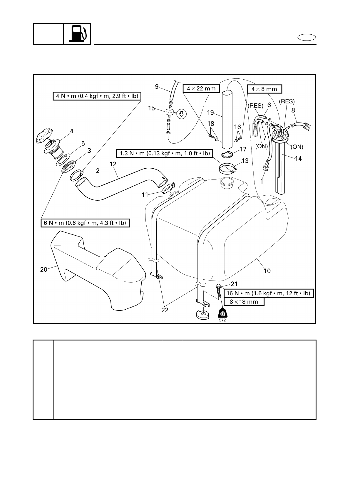
4-7
FUEL
E
FUEL TANK
EXPLODED DIAGRAM
Step Procedure/Part name Q’ty Service points
7 Fuel hose 1
8 Fuel return hose 1
9 Fuel tank breather hose 1
10 Fuel tank assembly 1
11 Hose clamp 1
12 Fuel filler hose 1
13 Hose clamp 1
14 Fuel sensor assembly 1

4-8
FUEL
E
FUEL TANK
EXPLODED DIAGRAM
Step Procedure/Part name Q’ty Service points
15 One way valve 1
16 Screw/washer 1/1
17 Filter 1
18 Screw/washer 1/1
19 Sleeve 1
20 Floatation 1
21 Bolt 2
22 Tank belt 2
Reverse the removal steps for installation.
4-9
FUEL
E
FUEL TANK
SERVICE POINTS
Check valve inspection
1. Check:
● Check valve
Faulty → Replace.
Fuel level sensor inspection
Refer to “INDICATION SYSTEM” in
chapter 7.
Fuel tank inspection
1. Inspect:
● Fuel tank
Cracks/damage → Replace.
Pipe joint inspection
1. Inspect:
● Pipe
Contaminants → Clean.
Bends/damage → Replace.
Checking steps:
● Connect a hose to the end of check
valve “A” and blow into it.
Air should come out from end “B”.
● Connect the hose to the end of check
valve “B” and blow into it.
Air should not come out from end “A”.
A
A
B
B
4-10
FUEL
E
INTAKE SILENCER
INTAKE SILENCER
EXPLODED DIAGRAM
REMOVAL AND INSTALLATION CHART
Step Procedure/Part name Q’ty Service points
INTAKE SILENCER REMOVAL Follow the left “Step” for removal.
1 Bolt 3
2 Intake silencer cover 1
3 Bolt 4
4 Spark arrester 1
5 Intake silencer 1
6 O-ring 2
Reverse the removal steps for installation.
4-11
FUEL
E
CARBURETOR UNIT
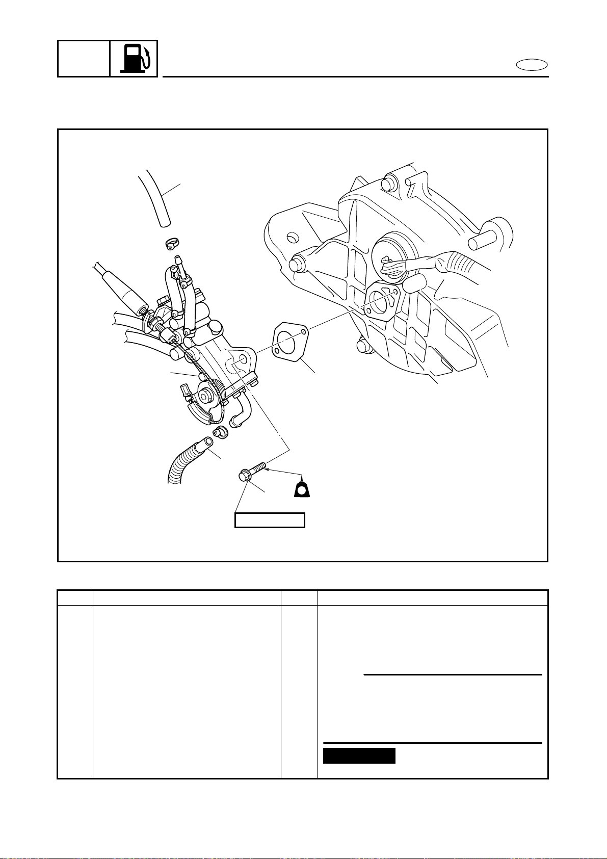
CARBURETOR UNIT
EXPLODED DIAGRAM
REMOVAL AND INSTALLATION CHART
Step Procedure/Part name Q’ty Service points
CARBURETOR REMOVAL Follow the left “Step” for removal.
Battery box Refer to “BATTERY BOX” in chapter 8.
Intake silencer Refer to “INTAKE SILENCER”.
1 Bolt 2
NOTE:
When removing the carburetor, the
exhaust chamber assembly does not
need to be removed if the engine unit has
already been removed.
2 Thermoswitch 1
3 Clamp/cooling water hose 1/1
4 Grease hose 1
5 Clamp/cooling water hose 1/1 Å For cooling water pilot outlet on
starboard side
6 Clamp/cooling water hose 1/1 ı For cooling water pilot outlet on port
side

4-12
FUEL
E
CARBURETOR UNIT
EXPLODED DIAGRAM
Step Procedure/Part name Q’ty Service points
7 Hose clamp 2 Slide the outer exhaust joint.
8 Hose clamp 2
9 Floatation 1
10 Water lock band 1
11 Bolt 1
12 Bolt 1
13 Muffler stay 3 1
14 Bolt 4
15 Nut/washer 2/2

4-13
FUEL
E
CARBURETOR UNIT
EXPLODED DIAGRAM
Step Procedure/Part name Q’ty Service points
16 Muffler stay 1 2
NOTE:
Make sure to remove spark plugs before
removing the muffler stay 1.
17 Bolt 2
18 Hose clamp 2
19 Exhaust chamber assembly 1
20 Rubber joint 1 Slide the water lock to back
21 Outer exhaust joint 1
22 Inner exhaust joint 1
4-14
FUEL
E
CARBURETOR UNIT
EXPLODED DIAGRAM
Step Procedure/Part name Q’ty Service points
23 Fuel hose 2 Å suction
ı return
NOTE:
Use the white marks a on the fuel hoses
to distinguish the hose ends.
24 Oil feed hose 2
25 Choke cable 1
26 Throttle cable 1
27 Oil pump cable 1
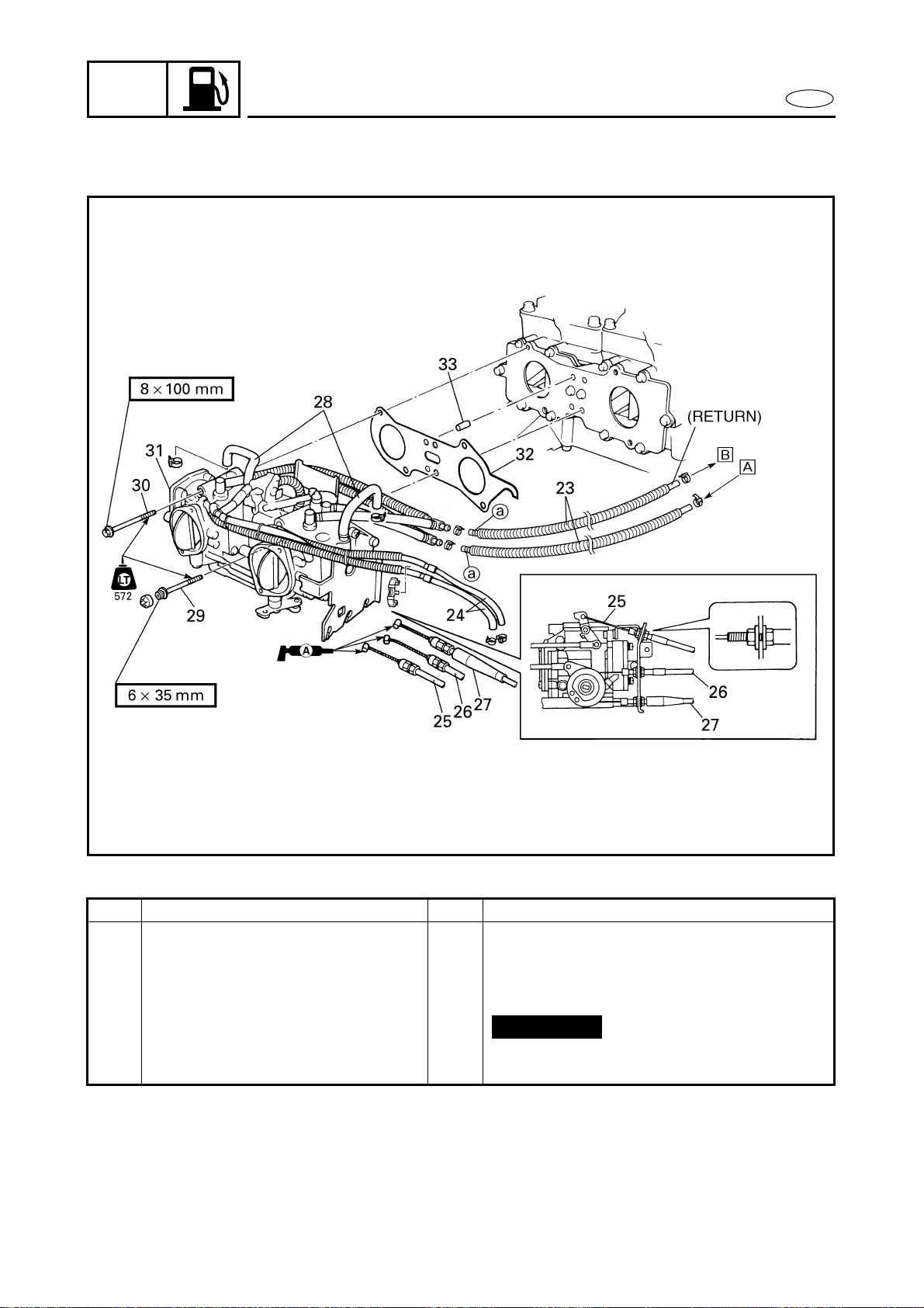
4-15
FUEL
E
CARBURETOR UNIT
EXPLODED DIAGRAM
Step Procedure/Part name Q’ty Service points
28 Pulse hose 2
29 Bolt 2
30 Bolt 4
31 Carburetor unit 1
32 Gasket 1
33 Dowel pin 2
Reverse the removal steps for installation.
Not reusable
4-16
FUEL
E
CARBURETOR UNIT
EXPLODED DIAGRAM
REMOVAL AND INSTALLATION CHART
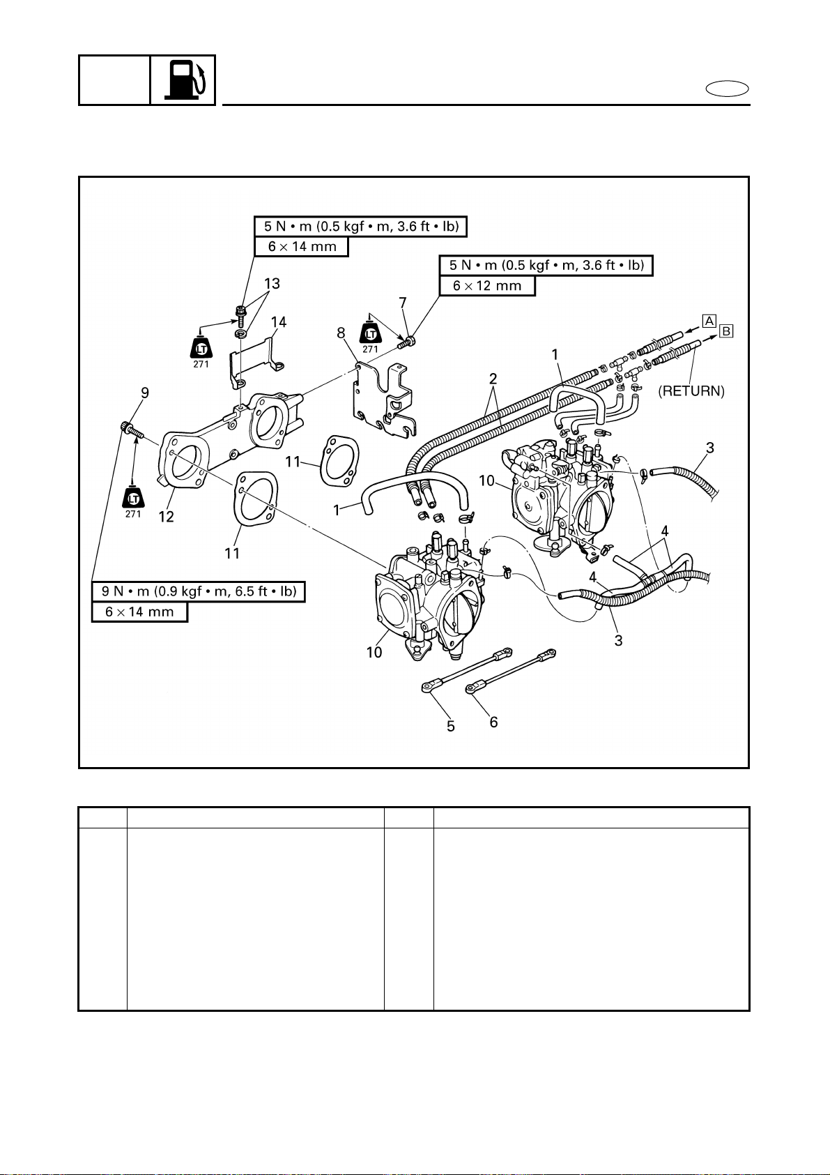
Step Procedure/Part name Q’ty Service points
CARBURETOR UNIT
SEPARATION
Follow the left “Step” for removal.
1 Pulse hose 2
2 Fuel hose 4 Å suction
ı return
3 Oil feed hose 2
4 Accelerator pump fuel hose 3
5 Throttle link 1
6 Choke link 1
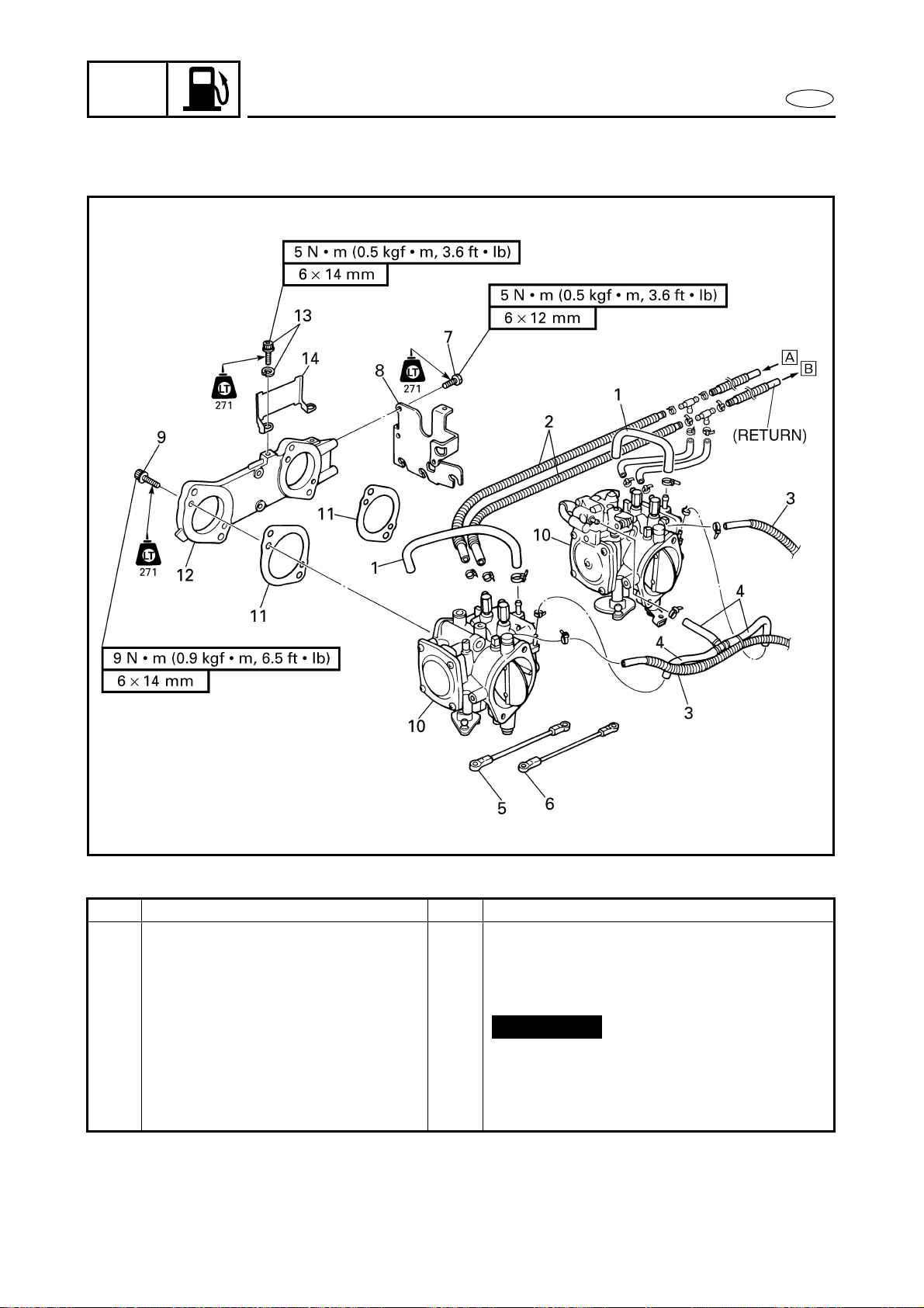
4-17
FUEL
E
CARBURETOR UNIT
EXPLODED DIAGRAM
Step Procedure/Part name Q’ty Service points
7 Bolt 3
8 Cable bracket 1
9 Bolt 4
10 Carburetor 2
11 Gasket 2
12 Carburetor joint 1
13 Bolt/washer 2/2
14 Fuel hose guide 1
Reverse the removal steps for installation.
Not reusable
4-18
FUEL
E
CARBURETOR UNIT
SERVICE POINTS
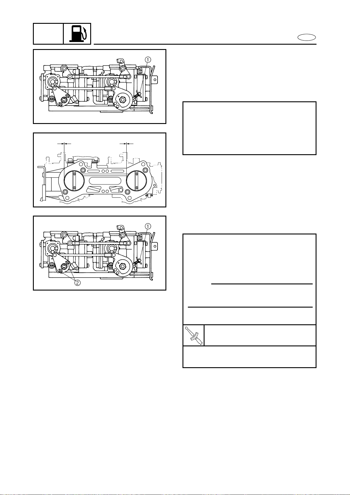
Throttle valve synchronization inspection
and adjustment
1. Check:
● Throttle valve synchronization
Different clearances → Adjust.
Checking steps:
● Loosen the throttle stop screw 1 until
untouched the screw end from the
throttle lever.
● Check the each throttle valve is fully
closed a.
aa
2. Adjust:
● Throttle valve synchronization
Adjustment steps:
● Loosen the throttle stop screw 1 until
untouched the screw end from the
throttle lever.
● Loosen the screws 2.
NOTE:
Make sure that the throttle valves are in
the fully closed position.
● Tighten the screws 2.
T
R
.
.
Screw:
2 N • m (0.2 kgf • m, 1.4 ft • lb)
● Turn in the throttle stop screw to the
original position.
4-19
FUEL
E
CARBURETOR UNIT
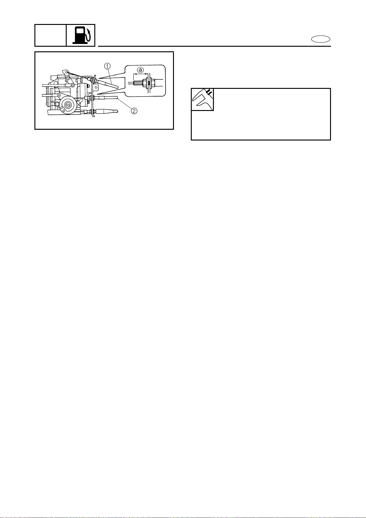
Choke cable and throttle cable installation
1. Install:
● Choke cable 1
● Throttle cable 2
2. Adjust:
● Throttle lever free play
● Choke lever operation
Refer to “CONTROL SYSTEM” in
chapter 3.
Choke cable guide installation
position a:
13–15 mm (0.51–0.59 in)
Throttle cable guide installation
position a:
18–20 mm (0.71–0.79 in)
Oil pump cable installation
1. Adjust:
● Oil pump cable
Refer to “OIL PUMP”.
Carburetor assembly
1. Adjust:
● Trolling speed
Refer to “FUEL SYSTEM” in chapter 3.
4-20
FUEL
E
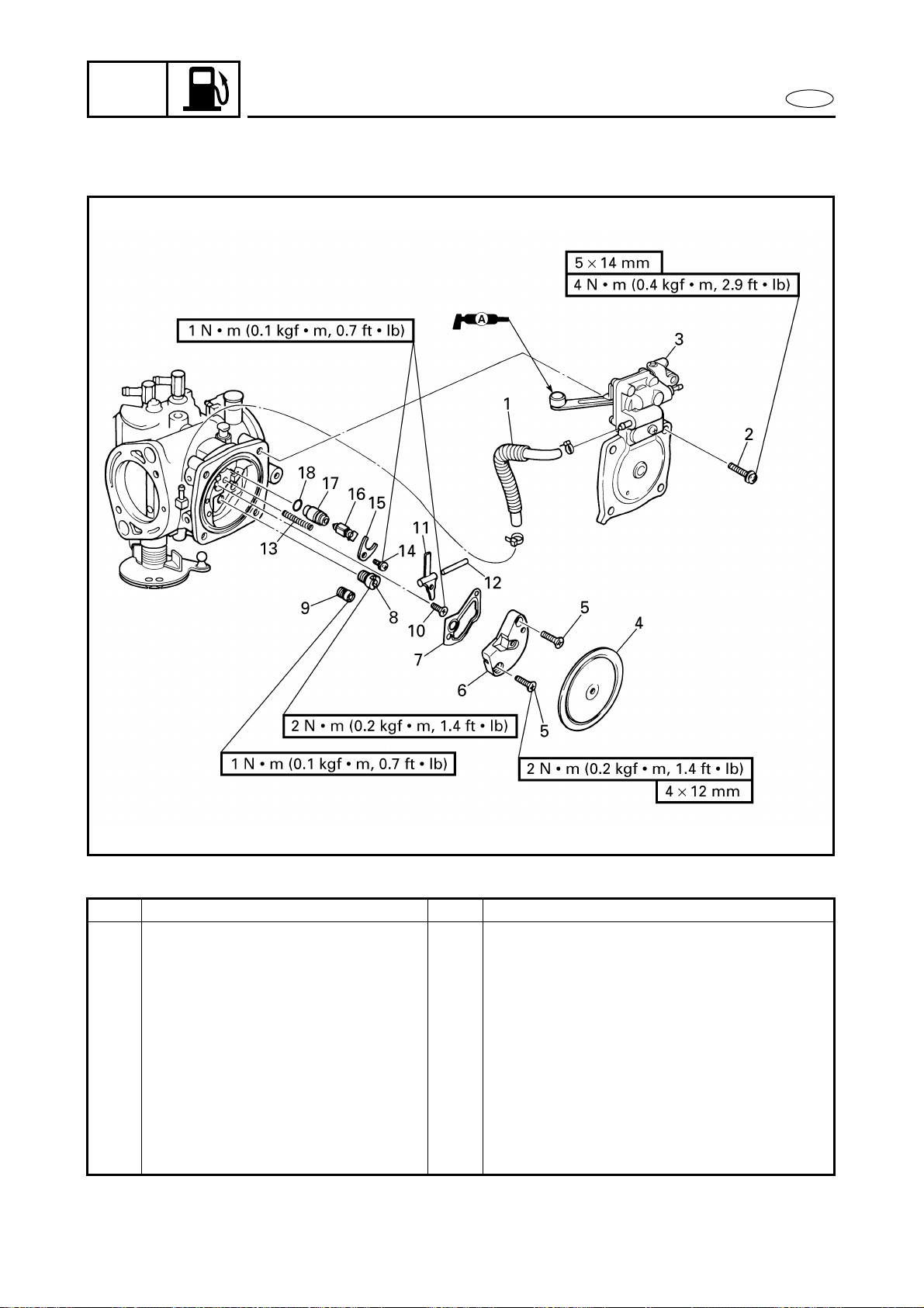
CARBURETOR
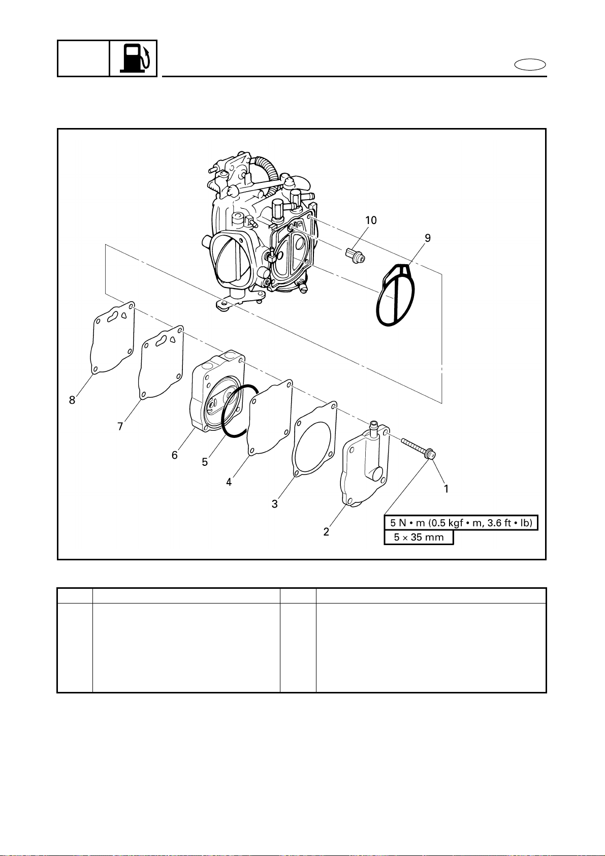
CARBURETOR
EXPLODED DIAGRAM
REMOVAL AND INSTALLATION CHART
Step Procedure/Part name Q’ty Service points
CARBURETOR DISASSEMBLY Follow the left “Step” for disassembly.
1 Accelerator pump fuel hose 1 Carburetor #1
2 Screw 4
3 Accelerator pump/carburetor
cover
1/1 Carburetor #1/carburetor #2
4 Diaphragm 1
5 Screw 2
6 Regulator body 1
7 Gasket 1
8 Main jet 1
9 Pilot jet 1

4-21
FUEL
E
CARBURETOR
EXPLODED DIAGRAM
Step Procedure/Part name Q’ty Service points
10 Screw 1
11 Arm 1
12 Arm pin 1
13 Spring 1
14 Screw 1
15 Needle valve seat holder 1
16 Needle valve 1
17 Needle valve seat 1
18 O-ring 1
Reverse the disassembly steps for
assembly.
4-22
FUEL
E
CARBURETOR
EXPLODED DIAGRAM
REMOVAL AND INSTALLATION CHART
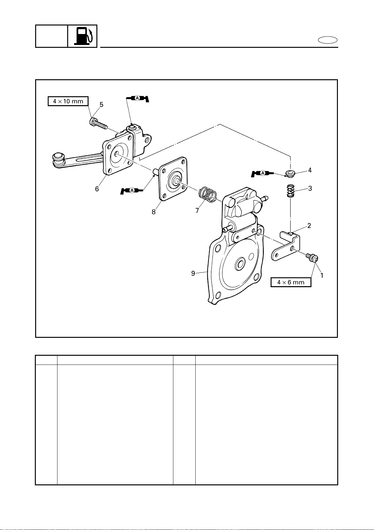
Step Procedure/Part name Q’ty Service points
ACCELERATOR PUMP
DISASSEMBLY
Follow the left “Step” for disassembly.
1 Screw 1
2 Stay 1
3 Spring 1
4 Spring seat 1
5 Screw 4
6 Accelerator pump cover 1
7 Spring 1
8 Diaphragm 1
9 Accelerator pump body 1
Reverse the disassembly steps for
assembly.
4-23
FUEL
E
CARBURETOR
SERVICE POINTS
NOTE:
Before disassembling the carburetor, make
sure to note the number of times the pilot
screw is turned in from its set position to
the seated position.
CAUTION:
Do not use steel wire for cleaning the jets.
This may enlarge the jet diameters and
seriously affect performance.
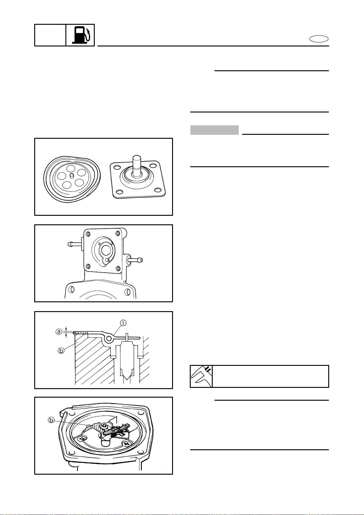
Diaphragm inspection
1. Inspect:
● Diaphragm
Damage → Replace.
Accelerator pump body inspection
1. Inspect:
● One way valve
Crack/damage → Replace the acceler-
ator pump body.
● Fuel passage
Clog → Clean or replace.
Arm inspection
1. Inspect:
● Arm 1
Bends/damage → Repair or replace.
2. Measure:
● Arm height a
NOTE:
● Measure the distance between the surface
of the carburetor body b and the top sur-
face of the arm.
● The arm should be resting on the needle
valve, but not compressing it.
Arm height:
0–0.2 mm (0–0.008 in)
4-24
FUEL
E
Regulator body inspection
1. Inspect:
● Regulator body
Contaminants → Clean.
Damage → Replace.
● Valve (clear film) 1
Damage → Replace.
Needle valve inspection
1. Inspect:
● Needle valve
● Needle valve seat
Contaminants a → Clean.
Wear b → Replace.
NOTE:
Always replace the needle valve and needle
valve seat as a set.
Jet and carburetor body inspection
1. Inspect:
● Main jet
● Pilot jet
● Carburetor body
Clog/contaminants → Clean.
Damage/wear → Replace.
CAUTION:
Do not use a steel wire to clean the jets.
This may enlarge the jet diameters and
seriously affect performance.
Carburetor assembly
NOTE:
Before assembling the carburetor, make
sure to turn out the pilot screw the same
number of times, as noted before disassem-
bly, from the seated position to the set posi-
tion.
1. Adjust:
● Trolling speed
Refer to “FUEL SYSTEM” in chapter 3.
CARBURETOR
4-25
FUEL
E
FUEL PUMP
FUEL PUMP
EXPLODED DIAGRAM
REMOVAL AND INSTALLATION CHART
Step Procedure/Part name Q’ty Service points
FUEL PUMP DISASSEMBLY Follow the left “Step” for disassembly.
Carburetors Refer to “CARBURETOR UNIT”.
1 Screw 4
2 Fuel pump cover 1
3 Gasket 1
4 Diaphragm 1
5 O-ring 1
6 Diaphragm body 1
Not reusable
4-26
FUEL
E
FUEL PUMP
EXPLODED DIAGRAM
Step Procedure/Part name Q’ty Service points
7 Rubber diaphragm 1
8 Diaphragm 1
9 Packing 1
10 Fuel filter 1
Reverse the disassembly steps for
assembly.

4-27
FUEL
E
FUEL PUMP
SERVICE POINTS
Fuel pump inspection
1. Inspect:
● Diaphragm
● Rubber diaphragm
● Diaphragm body
Damage → Replace.
Fuel filter inspection
1. Inspect:
● Fuel filter
Clog/contaminants → Clean.
Damage → Replace.
4-28
FUEL
E
OIL PUMP
OIL PUMP
EXPLODED DIAGRAM
REMOVAL AND INSTALLATION CHART
Step Procedure/Part name Q’ty Service points
OIL PUMP REMOVAL Follow the left “Step” for removal.
Exhaust chamber assembly Refer to “CARBURETOR UNIT”.
Oil pump cable and oil feed
hoses
Refer to “CARBURETOR UNIT”.
1 Oil return hose 1
NOTE:
When removing the oil pump, the exhaust
chamber assembly does not need to be
removed if the engine unit has already
been removed.
2 Oil hose 1
3 Bolt 2
4 Oil pump assembly 1
5 Gasket 1
Reverse the removal steps for installation.
4
2
6 × 20 mm
LTLT
LT
572572
3
5
1
Not reusable
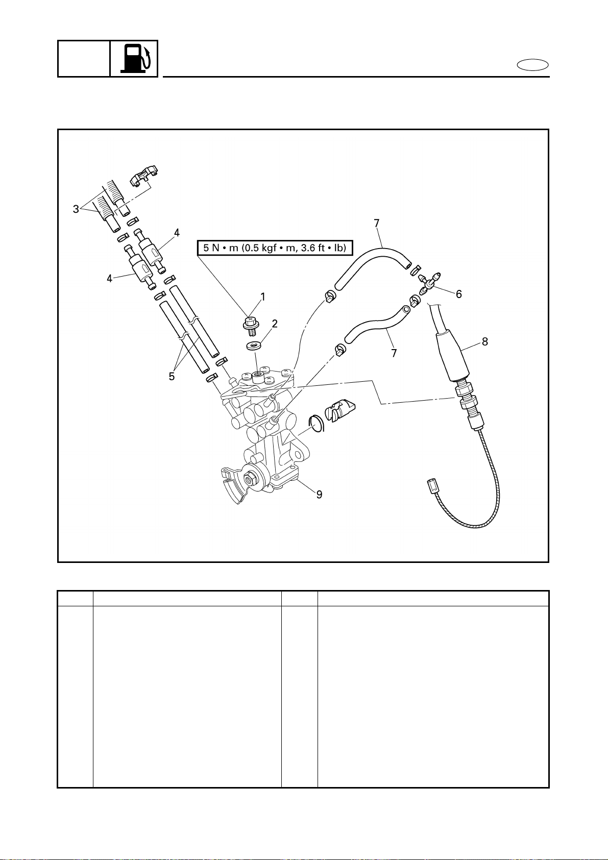
4-29
FUEL
E
OIL PUMP
EXPLODED DIAGRAM
REMOVAL AND INSTALLATION CHART
Step Procedure/Part name Q’ty Service points
OIL PUMP HOSES AND CABLE
REMOVAL
Follow the left “Step” for removal.
1 Air bleed screw 1
2 Gasket 1
3 Oil feed hose 1 2
4 Check valve 2
5 Oil feed hose 2 2
6 Hose joint 1
7 Oil return hose 2
8 Oil pump cable 1
9 Oil pump 1
Reverse the removal steps for installation.
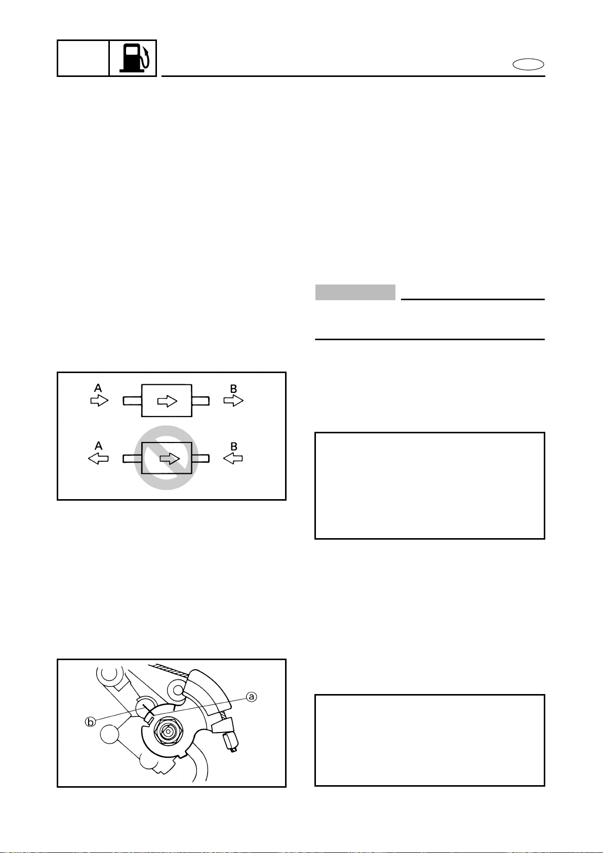
4-30
FUEL
E
OIL PUMP
SERVICE POINTS
Oil pump inspection
1. Inspect:
● Oil pump
Contaminants → Clean.
Damage/wear → Replace.
● Oil pump joint piece
Damage/wear → Replace.
Oil hose inspection
1. Inspect:
● Oil hose
Cracks/damage → Replace.
CAUTION:
If the oil feed hoses are not full of oil, fill
them up.
Check valve inspection
1. Check:
● Check valve
Faulty → Replace.
Oil pump cable adjustment
1. Check:
● Oil pump lever position
Incorrect → Adjust.
Checking steps:
● Connect a hose to the end of check
valve “A” and blow into it.
Air should come out from end “B”.
● Connect the hose to the end of check
valve “B” and blow into it.
Air should not come out from end “A”.
Checking steps:
● Fully close the carburetor throttle
valves.
● Check that the mark a on the oil pump
lever is aligned with the mark b on the
oil pump body.
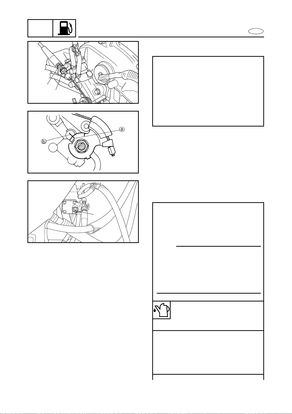
4-31
FUEL
E
OIL PUMP
2. Adjust:
● Oil pump cable
Adjustment steps:
● Loosen the locknut 1 and the adjust-
ing nut 2.
● Fully close the carburetor throttle
valves.
● Adjust the oil pump cable so that the
mark a on the oil pump lever is
aligned with the mark b on the oil
pump body.
● Tighten the adjusting nut and locknut.
1
2
Oil injection pump air bleeding
1. Bleed:
● Air
Air bleeding steps:
● Place rags around the air bleed screw
1 to catch any oil that might spill.
● Fill the oil tank with the recommended
oil.
NOTE:
If the oil pump is replaced or the oil suc-
tion hose is removed, bleed air from the
oil suction hose by removing it from the
oil pump.
After bleeding the air, reconnect the
hose with a locking tie.
Recommended engine oil:
YAMALUBE 2-W or an
equivalent TC-W3 certified
outboard oil
● Loosen the air bleed screw 1 two full
turns and make sure that both the oil
and air bubbles flow out.
● When there are no air bubbles left,
tighten the air bleed screw.
● Wipe up any spilt oil.
1
4-32
FUEL
E
OIL PUMP
T
R
.
.
Air bleed screw:
5 N • m (0.5 kgf • m, 3.6 ft • lb)
CAUTION:
Do not run the engine if oil does not
flow out of the air bleed screw. Inspect
the oil pump hoses for proper routing
and make sure there are no restrictions
in the line.

E
POWR
CHAPTER 5
POWER UNIT
ENGINE UNIT ................................................................................................. 5-1
EXPLODED DIAGRAM............................................................................. 5-1
REMOVAL AND INSTALLATION CHART ............................................... 5-1
SERVICE POINTS ..................................................................................... 5-5
Shim removal .................................................................................... 5-5
Engine mount inspection ................................................................. 5-5
Coupling clearance inspection......................................................... 5-5
EXHAUST CHAMBER ASSEMBLY................................................................ 5-6
EXPLODED DIAGRAM............................................................................. 5-6
REMOVAL AND INSTALLATION CHART ............................................... 5-6
EXHAUST CHAMBER JOINT....................................................................... 5-10
EXPLODED DIAGRAM........................................................................... 5-10
REMOVAL AND INSTALLATION CHART ............................................. 5-10
EXHAUST MANIFOLD ................................................................................. 5-12
EXPLODED DIAGRAM........................................................................... 5-12
REMOVAL AND INSTALLATION CHART ............................................. 5-12
REED VALVES .............................................................................................. 5-13
EXPLODED DIAGRAM........................................................................... 5-13
REMOVAL AND INSTALLATION CHART ............................................. 5-13
SERVICE POINTS ................................................................................... 5-14
Reed valve inspection..................................................................... 5-14
YPVS ............................................................................................................. 5-15
EXPLODED DIAGRAM........................................................................... 5-15
REMOVAL AND INSTALLATION CHART ............................................. 5-15
SERVICE POINTS ................................................................................... 5-17
YPVS valve inspection .................................................................... 5-17
YPVS valve installation................................................................... 5-17
CYLINDER HEAD .......................................................................................... 5-18
EXPLODED DIAGRAM........................................................................... 5-18
REMOVAL AND INSTALLATION CHART ............................................ 5-18
SERVICE POINTS ................................................................................... 5-19
Cylinder head inspection................................................................ 5-19

E
1
2
3
4
5
6
7
8
9
POWR
CYLINDERS................................................................................................... 5-20
EXPLODED DIAGRAM........................................................................... 5-20
REMOVAL AND INSTALLATION CHART ............................................. 5-20
SERVICE POINTS ................................................................................... 5-21
Cylinder inspection ......................................................................... 5-21
PISTONS ....................................................................................................... 5-22
EXPLODED DIAGRAM........................................................................... 5-22
REMOVAL AND INSTALLATION CHART ............................................. 5-22
SERVICE POINTS ................................................................................... 5-24
Piston pin clip removal and installation........................................ 5-24
Piston inspection............................................................................. 5-24
Cylinder and piston combination .................................................. 5-25
Piston ring inspection ..................................................................... 5-25
Piston pin and bearing inspection ................................................. 5-26
STARTER MOTOR........................................................................................ 5-28
EXPLODED DIAGRAM........................................................................... 5-28
REMOVAL AND INSTALLATION CHART ............................................ 5-28
FLYWHEEL MAGNETO ................................................................................ 5-29
EXPLODED DIAGRAM........................................................................... 5-29
REMOVAL AND INSTALLATION CHART ............................................. 5-29
SERVICE POINTS ................................................................................... 5-34
Drive coupling removal and installation ....................................... 5-34
Flywheel magneto removal and installation ................................ 5-34
Drive coupling inspection............................................................... 5-35
Flywheel magneto inspection ........................................................ 5-35
Starter clutch assembly inspection ............................................... 5-35
CRANKCASE................................................................................................. 5-36
EXPLODED DIAGRAM........................................................................... 5-36
REMOVAL AND INSTALLATION CHART ............................................. 5-36
SERVICE POINTS ................................................................................... 5-38
Crankcase inspection ...................................................................... 5-38
Crankcase installation..................................................................... 5-38
CRANKSHAFT............................................................................................... 5-39
EXPLODED DIAGRAM........................................................................... 5-39
REMOVAL AND INSTALLATION CHART ............................................. 5-39
SERVICE POINTS ................................................................................... 5-40
Crankshaft inspection ..................................................................... 5-40

5-1
POWR
E
ENGINE UNIT
EXPLODED DIAGRAM
REMOVAL AND INSTALLATION CHART
Step Procedure/Part name Q’ty Service points
ENGINE UNIT REMOVAL Follow the left “Step” for removal.
Battery box Refer to “BATTERY BOX” in chapter 8.
YPVS cables and YPVS
servomotor
Refer to “YPVS SERVOMOTOR” in
chapter 7.
Intake silencer Refer to “INTAKE SILENCER” in
chapter 4.
Choke cable, throttle cable and
fuel hoses
Refer to “CARBURETOR UNIT” in
chapter 4.
1 Coupler 3
2 Band 6
3 Clamp/Cooling water hose 1
ENGINE UNIT
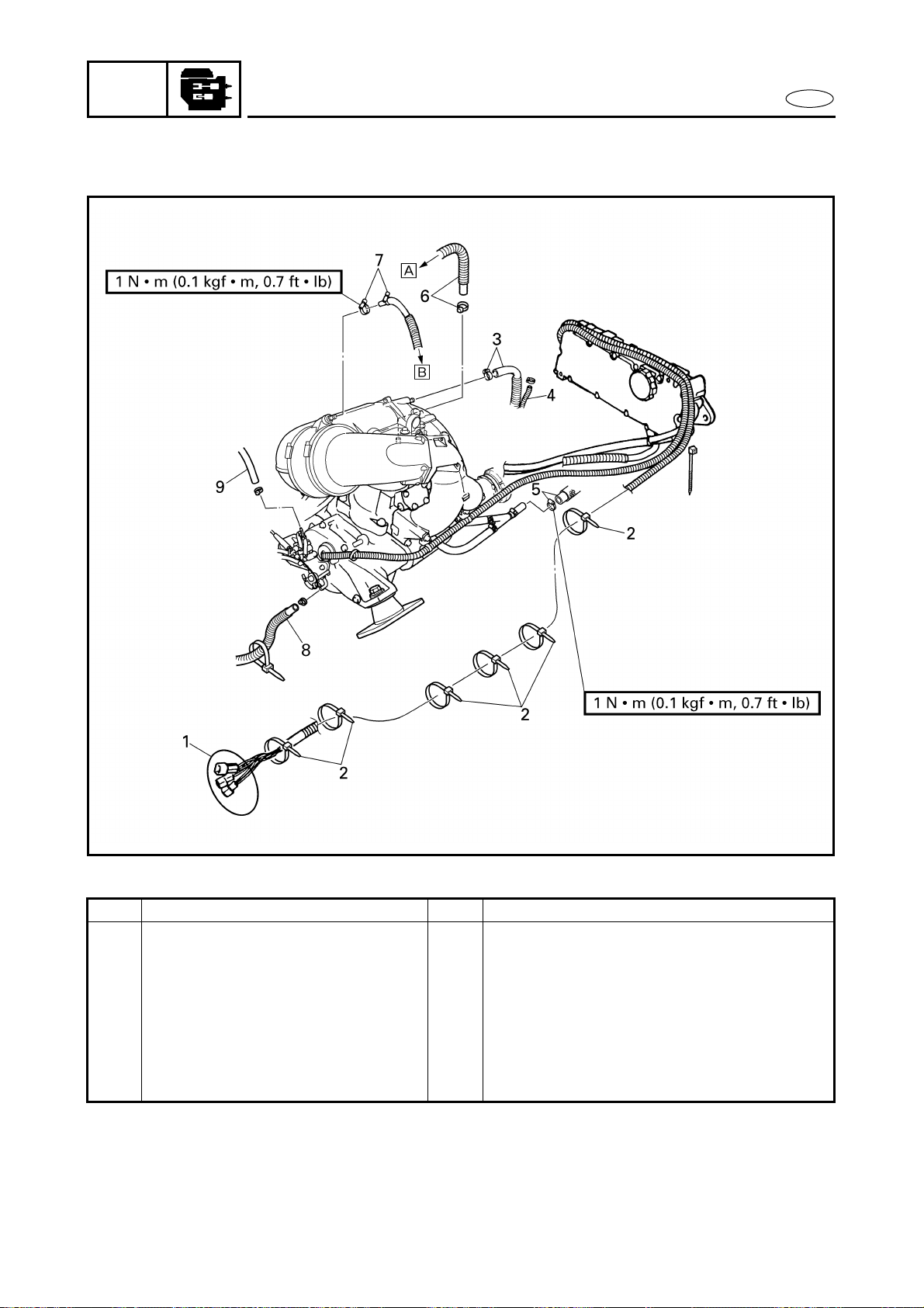
5-2
POWR
E
ENGINE UNIT
EXPLODED DIAGRAM
Step Procedure/Part name Q’ty Service points
4 Grease hose 1
5 Clamp/cooling water hose 1/1
6 Clamp/cooling water hose 1/1 Å For cooling water pilot outlet on
starboard side
7 Clamp/cooling water hose 1/1 ı For cooling water pilot outlet on port
side
8 Oil hose 1
9 Oil return hose 1
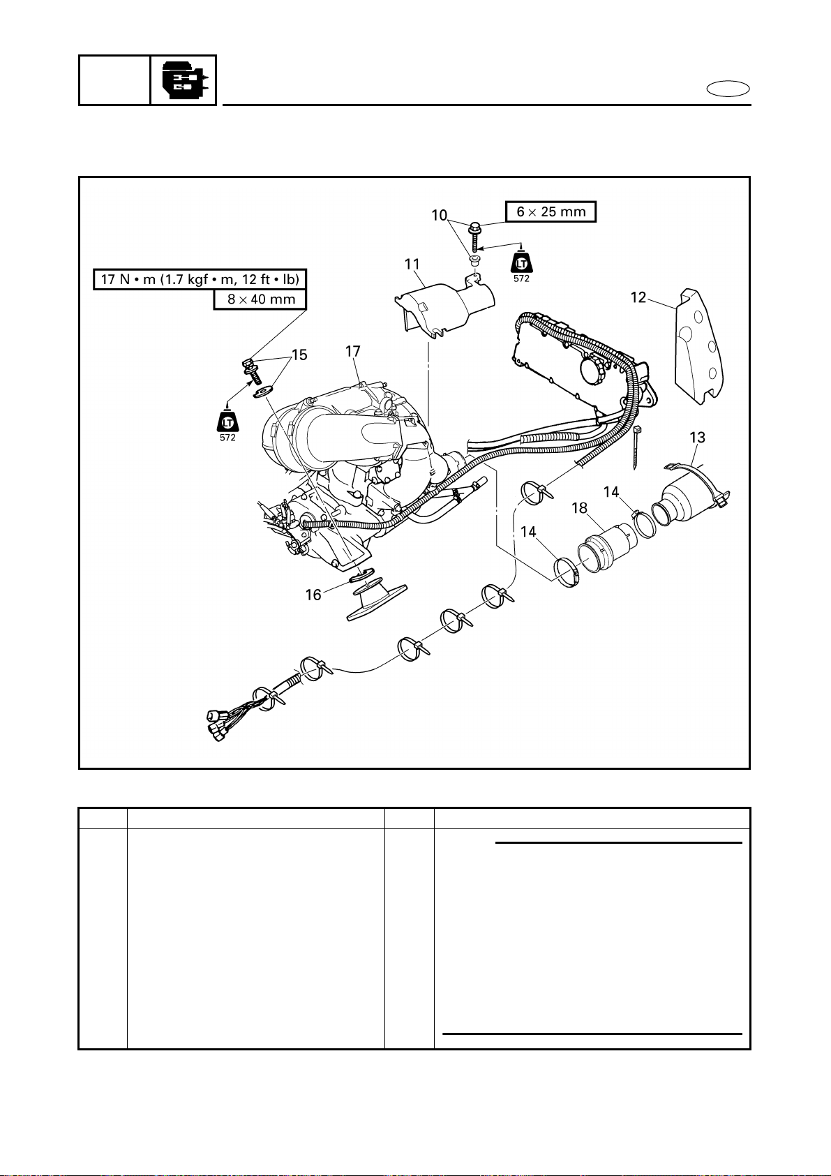
5-3
POWR
E
ENGINE UNIT
EXPLODED DIAGRAM
Step Procedure/Part name Q’ty Service points
10 Bolt/collar 1/1
NOTE:
● Before removing the engine unit, fix the
choke valves to the choke link with a
plastic band, etc. to the fully closed
position.
● When lifting the engine unit, hook the
hoister on the bow side of muffler stay
1.
● Lift the engine unit carefully trying not
hit it on the deck.
11 Coupling cover 1
12 Floatation 1
13 Water lock band 1
14 Hose clamp 2
15 Bolt/washer 4/4
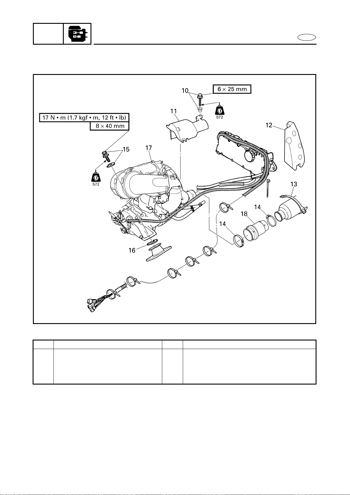
5-4
POWR
E
ENGINE UNIT
EXPLODED DIAGRAM
Step Procedure/Part name Q’ty Service points
16 Shim *
17 Engine unit 1
18 Rubber joint 1 Slide the water lock to back.
Reverse the removal steps for installation.
*: As required
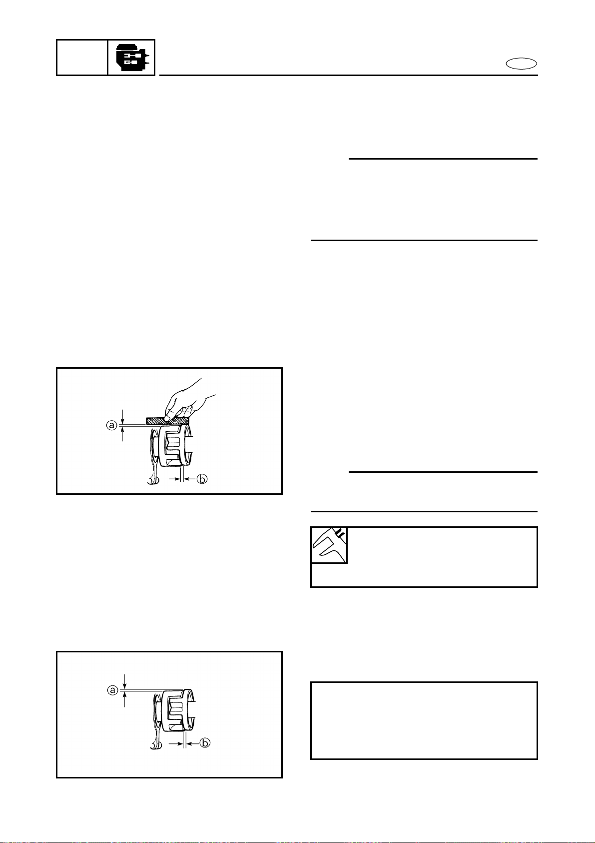
5-5
POWR
E
ENGINE UNIT
SERVICE POINTS
Shim removal
1. Remove:
● Shims
NOTE:
To ease reassembly and coupling align-
ment, remove the shims and organize them
in their respective groups (e.g., front right,
rear left) prior to removing the mounting
bolts.
Engine mount inspection
1. Inspect:
● Engine mounts
Cracks/damage → Replace.
Coupling clearance inspection
1. Measure:
● Clearance a
● Clearance b
(with the rubber damper)
Out of specification → Adjust.
NOTE:
Measure the clearances with a straightedge
and thickness gauge.
Clearance a:
0–0.5 mm (0–0.020 in)
Clearance b:
2–4 mm (0.079–0.157 in)
2. Adjust:
● Clearance a and b
Adjustment steps:
● Adjust the clearance a by adding or
removing shims.
● Adjust the clearance b by moving the
engine unit position.

5-6
POWR
E
EXHAUST CHAMBER ASSEMBLY
EXHAUST CHAMBER ASSEMBLY
EXPLODED DIAGRAM
REMOVAL AND INSTALLATION CHART
Step Procedure/Part name Q’ty Service points
EXHAUST CHAMBER
ASSEMBLY REMOVAL
Follow the left “Step” for removal.
Engine unit Refer to “ENGINE UNIT”.
1 Bolt 2
2 Thermoswitch 1
3 Hose clamp 2 Slide the outer exhaust joint.
4 Hose clamp 2
5 Bolt 1
6 Bolt 1
7 Muffler stay 3 1
8 Bolt 4
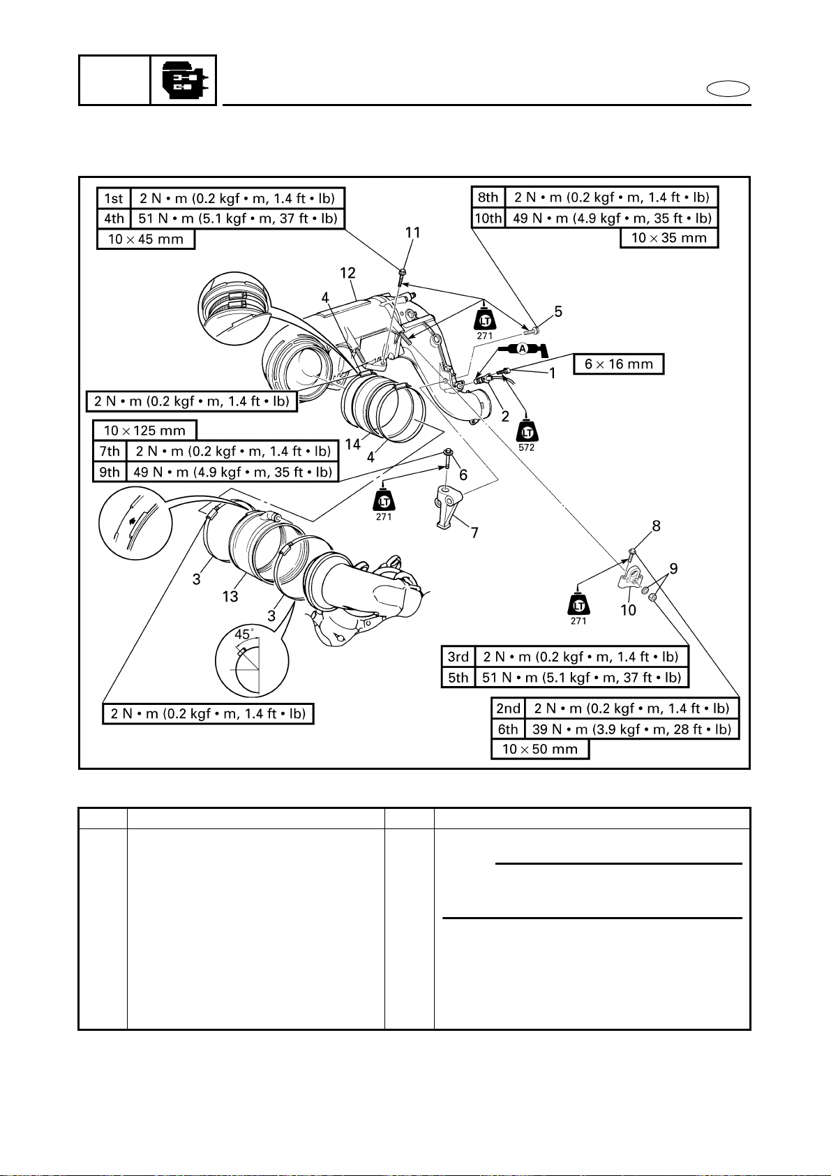
5-7
POWR
E
EXHAUST CHAMBER ASSEMBLY
EXPLODED DIAGRAM
Step Procedure/Part name Q’ty Service points
9 Nut/washer 2/2
10 Muffler stay 1 2
NOTE:
Make sure to remove spark plugs before
removing the muffler stay 1.
11 Bolt 2
12 Exhaust chamber assembly 1
13 Outer exhaust joint 1
14 Inner exhaust joint 1
Reverse the removal steps for installation.
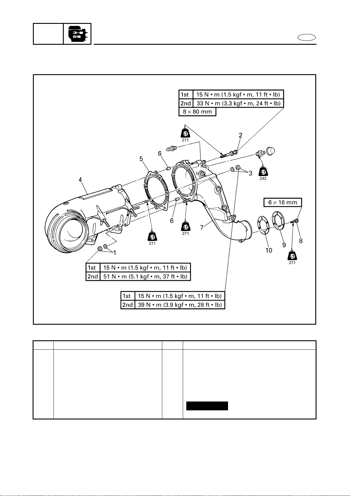
5-8
POWR
E
EXHAUST CHAMBER ASSEMBLY
EXPLODED DIAGRAM
REMOVAL AND INSTALLATION CHART
Step Procedure/Part name Q’ty Service points
EXHAUST CHAMBER
DISASSEMBLY
Follow the left “Step” for disassembly.
1 Nut/washer 1/1
2 Bolt 3
3 Nut/washer 2/2
4 Exhaust chamber 1
5 Gasket 1
6 Pin 2
Not reusable
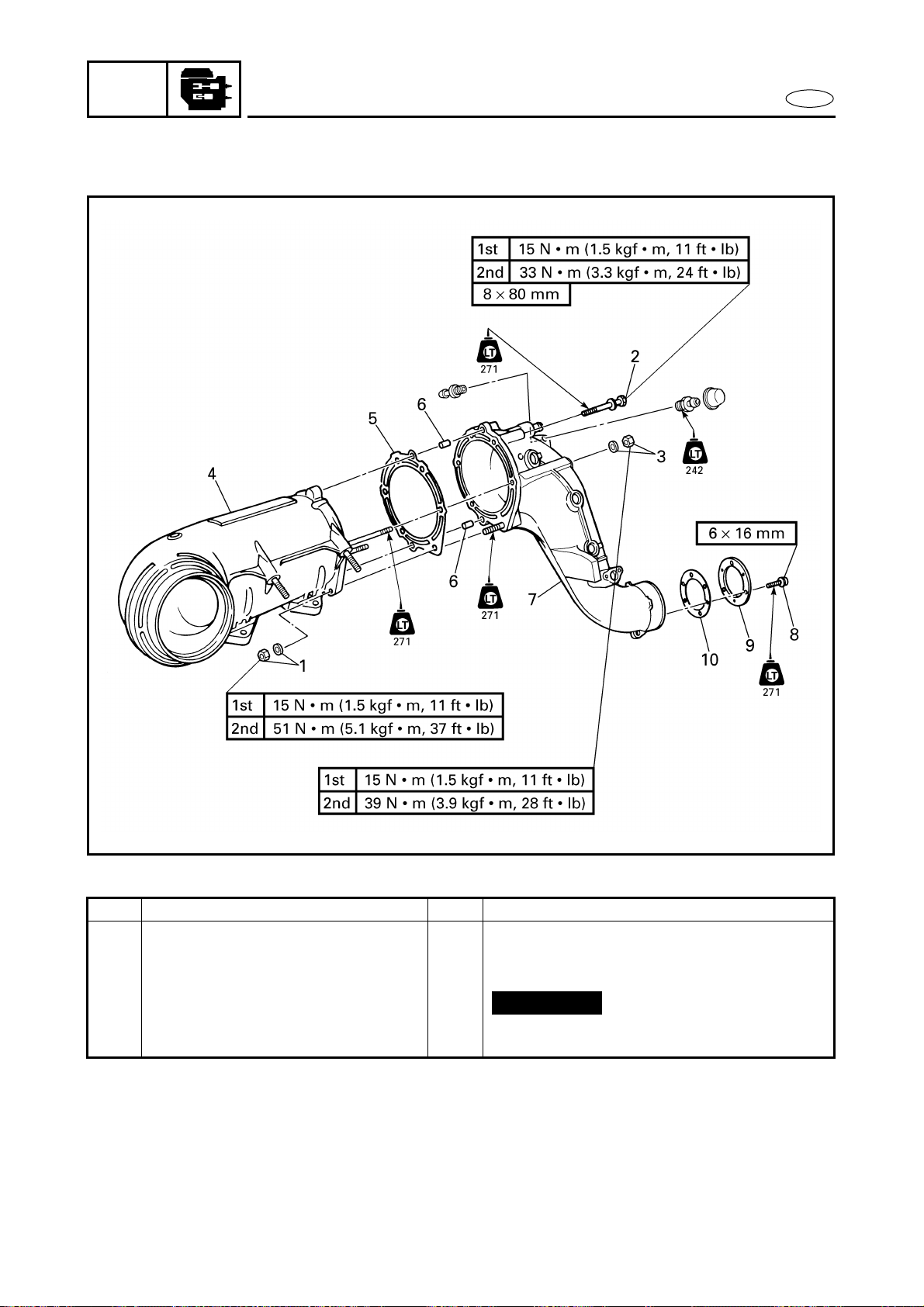
5-9
POWR
E
EXHAUST CHAMBER ASSEMBLY
EXPLODED DIAGRAM
Step Procedure/Part name Q’ty Service points
7 Muffler 1
8 Screw 3
9 Plate 1
10 Gasket 1
Reverse the disassembly steps for
assembly.
Not reusable
5-10
POWR
E
EXHAUST CHAMBER JOINT
EXHAUST CHAMBER JOINT
EXPLODED DIAGRAM
REMOVAL AND INSTALLATION CHART
Step Procedure/Part name Q’ty Service points
EXHAUST CHAMBER JOINT
REMOVAL
Follow the left “Step” for removal.
Exhaust chamber assembly Refer to “EXHAUST CHAMBER
ASSEMBLY”.
1 Clamp/cooling water hose 2/1 a white mark
2 Bolt 2
3 Bolt 1
4 Muffler stay 1
5 Bolt 1

5-11
POWR
E
EXHAUST CHAMBER JOINT
EXPLODED DIAGRAM
Step Procedure/Part name Q’ty Service points
6 Bolt 2
7 Bolt 2
8 Exhaust chamber joint 1
9 Gasket 1
10 Pin 2
Reverse the removal steps for installation.
Not reusable
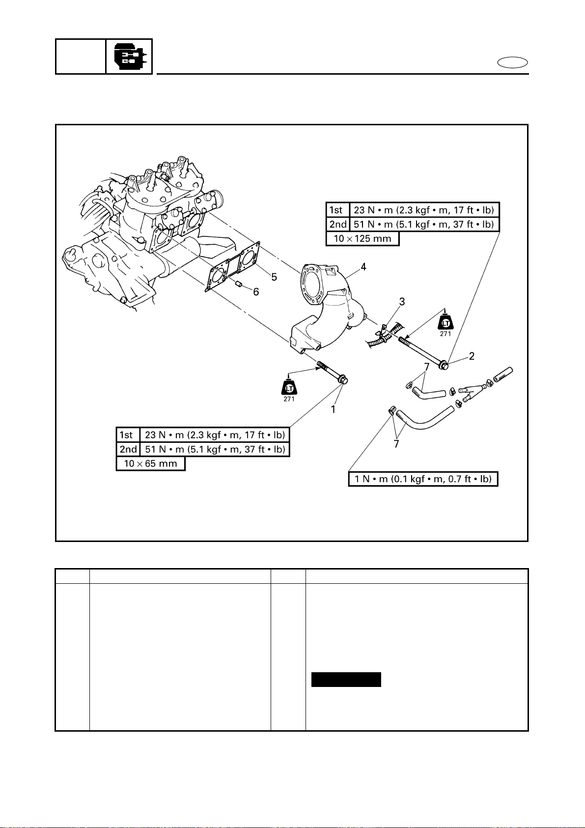
5-12
POWR
E
EXHAUST MANIFOLD
EXHAUST MANIFOLD
EXPLODED DIAGRAM
REMOVAL AND INSTALLATION CHART
Step Procedure/Part name Q’ty Service points
EXHAUST MANIFOLD REMOVAL Follow the left “Step” for removal.
Exhaust chamber joint Refer to “EXHAUST CHAMBER JOINT”.
1 Bolt 4
2 Bolt 4
3 Wire harness bracket 2
4 Exhaust manifold 1
5 Gasket 1
6 Pin 2
7 Clamp/cooling water hose 2/2
Reverse the removal steps for installation.
Not reusable
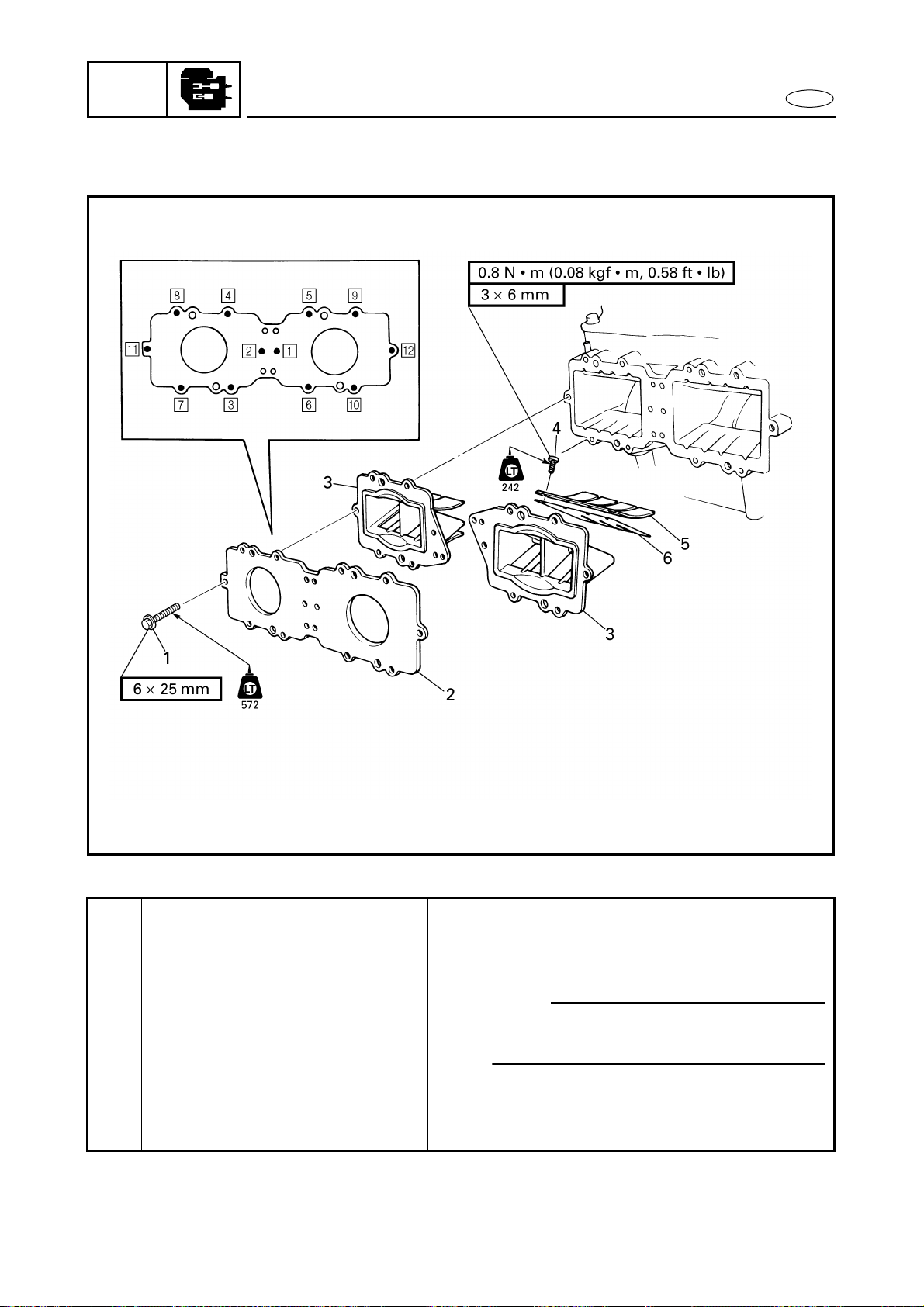
5-13
POWR
E
REED VALVES
REED VALVES
EXPLODED DIAGRAM
REMOVAL AND INSTALLATION CHART
Step Procedure/Part name Q’ty Service points
REED VALVE REMOVAL Follow the left “Step” for removal.
Carburetor unit Refer to “CARBURETOR UNIT” in
chapter 4.
1 Bolt 12
NOTE:
Tighten the bolts in the proper sequence
as shown.
2 Reed valve plate 1
3 Reed valve assembly 2
4 Screw 16
5 Valve stopper 4
6 Reed valve 4
Reverse the removal steps for installation.
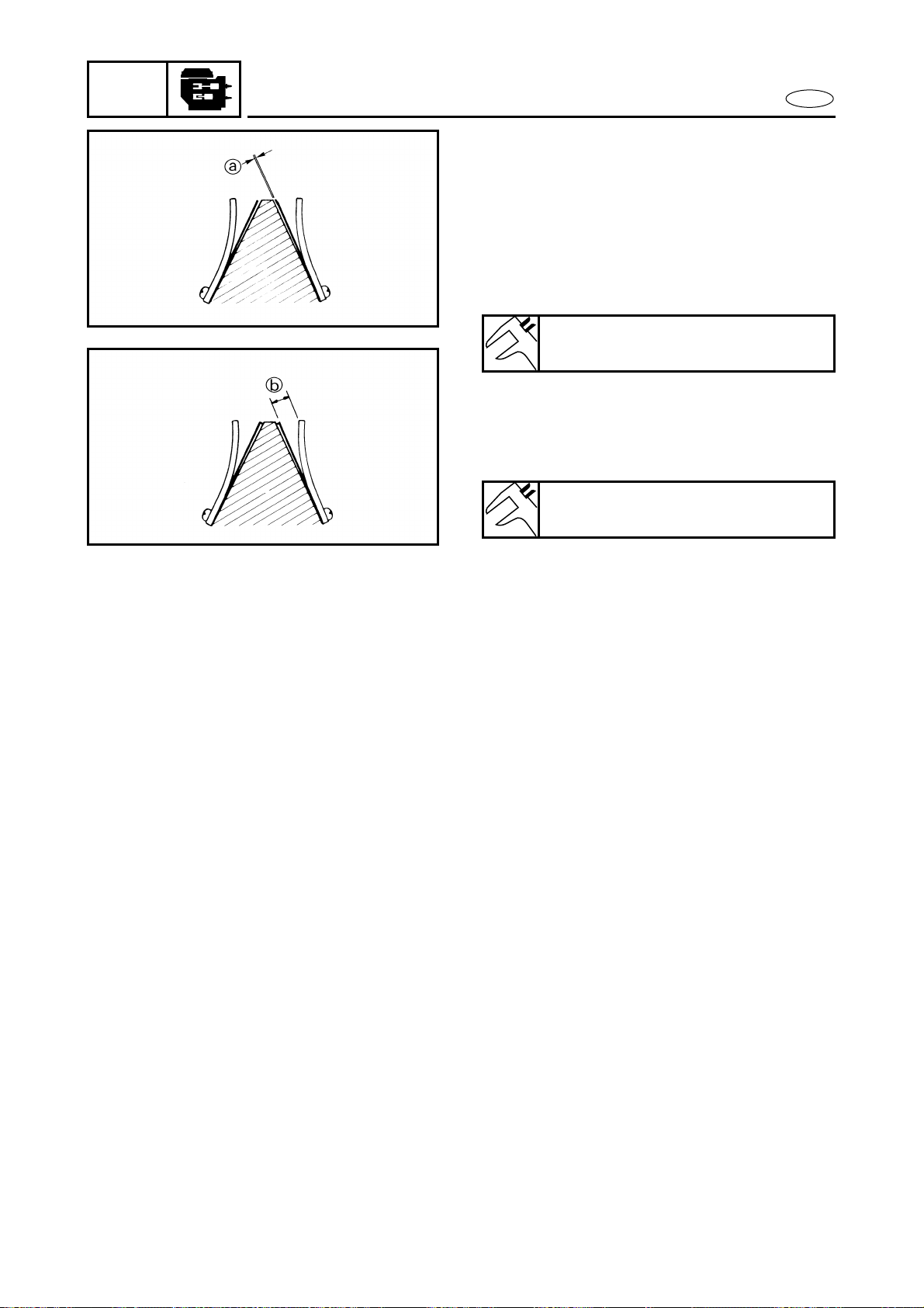
5-14
POWR
E
REED VALVES
SERVICE POINTS
Reed valve inspection
1. Inspect:
● Reed valves
Cracks/damage → Replace.
2. Measure:
● Valve bending a
Out of specification → Replace.
3. Measure:
● Valve stopper height b
Out of specification → Adjust or
replace.
Max. valve bending:
0.2 mm (0.01 in)
Valve stopper height:
10.8–11.4 mm (0.43–0.45 in)
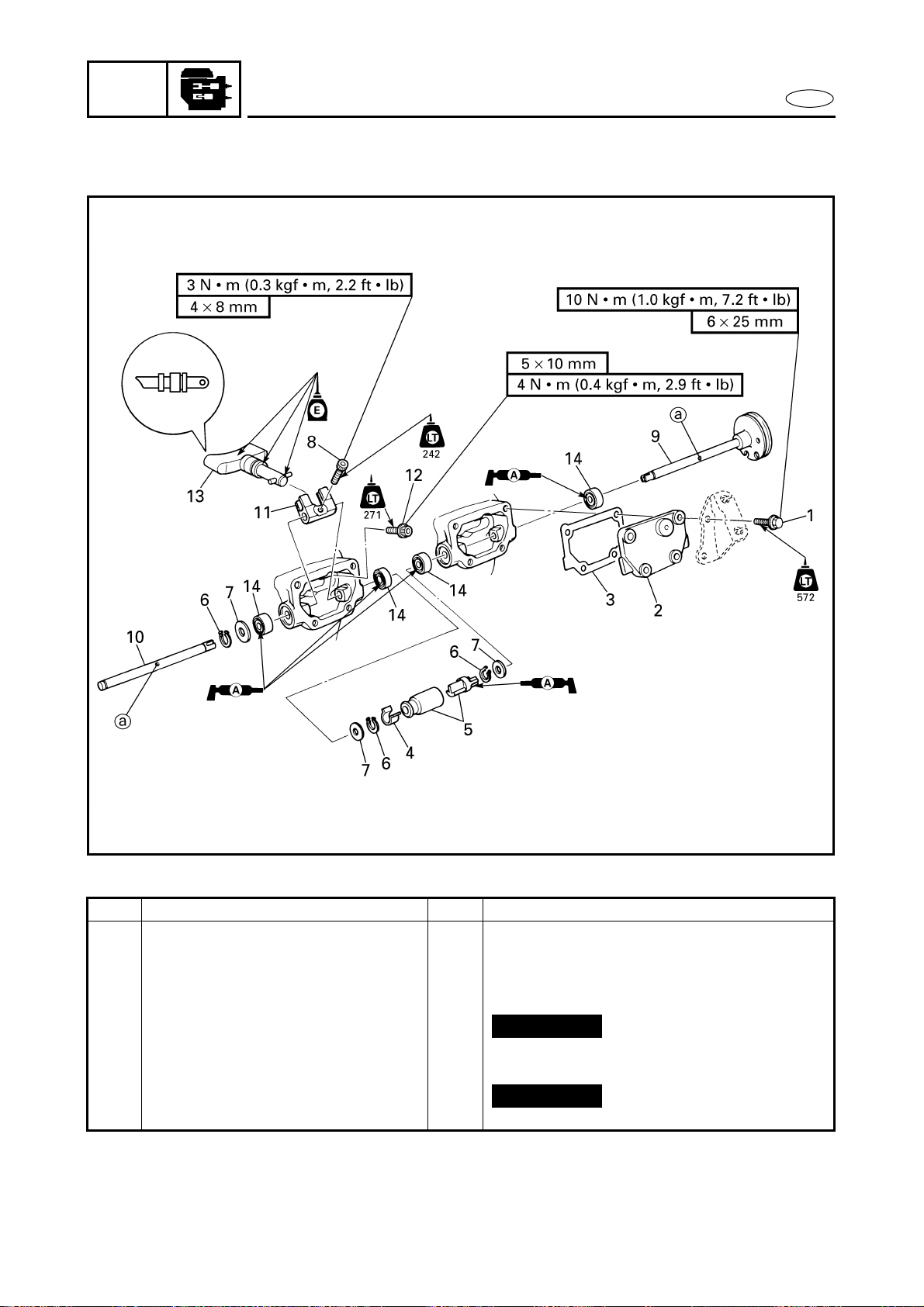
5-15
POWR
E
YPVS
YPVS
EXPLODED DIAGRAM
REMOVAL AND INSTALLATION CHART
Step Procedure/Part name Q’ty Service points
YPVS REMOVAL Follow the left “Step” for removal.
Exhaust manifold Refer to “EXHAUST MANIFOLD”.
1 Bolt 8
2 YPVS valve cover 2
3 Gasket 2
4 Spacer 1
5 Link joint/cover 1/1
6 Circlip 3
7 Washer 3
Not reusable
Not reusable
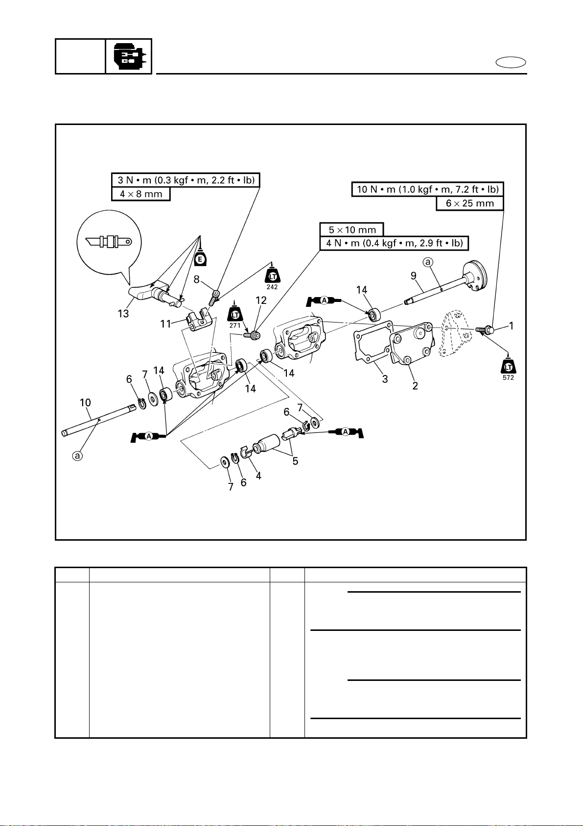
5-16
POWR
E
YPVS
EXPLODED DIAGRAM
Step Procedure/Part name Q’ty Service points
8 Bolt 2
NOTE:
During installation, align the hole a in
the YPVS shaft with the bolt.
9 Shaft 2 1
10 Shaft 1 1
11 YPVS valve lever 2
12 Bolt 2
13 YPVS valve assembly 2
14 Oil seal 4
NOTE:
If the YPVS shaft is removed, the oil seal
must be replaced.
Reverse the removal steps for installation.
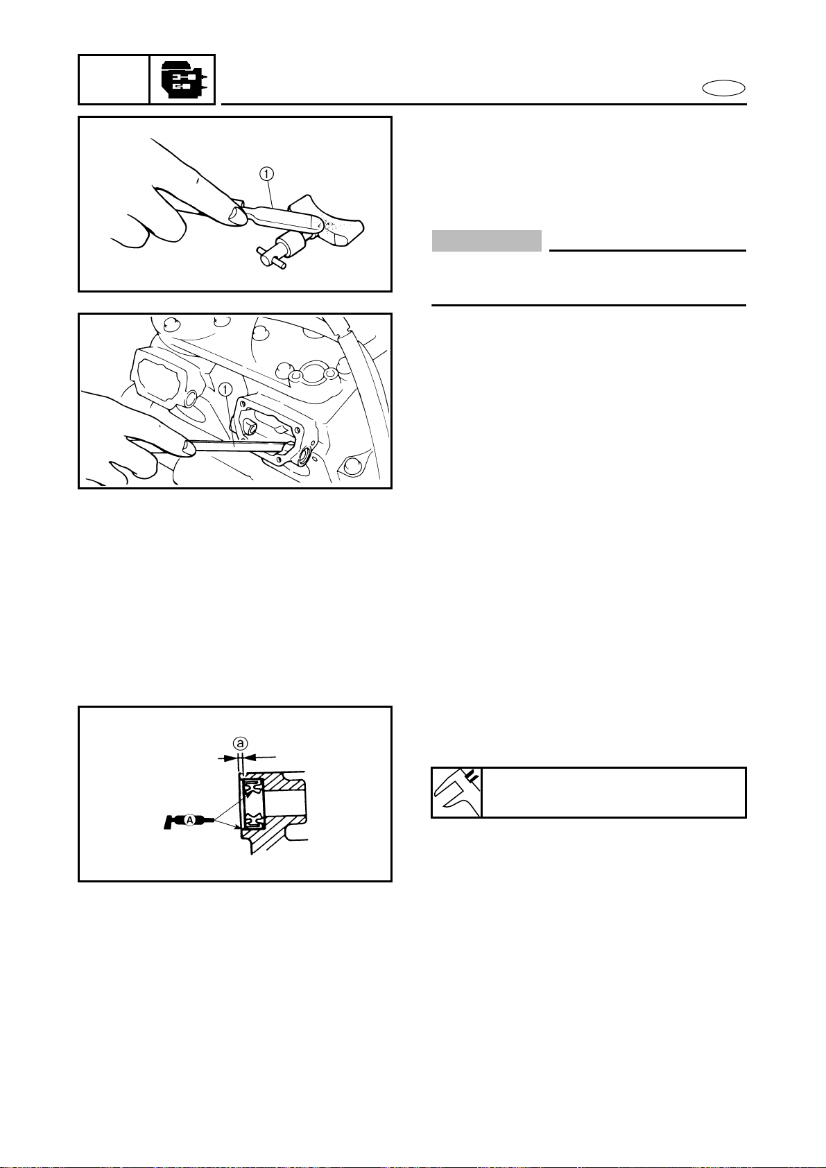
5-17
POWR
E
YPVS
SERVICE POINTS
YPVS valve inspection
1. Eliminate:
● Carbon deposits
(with a rounded scraper 1)
CAUTION:
Do not use a sharp instrument to avoid
damaging or scratching the surfaces.
2. Inspect:
● YPVS valve assembly
Crack/damage/wear → Replace.
YPVS valve installation
1. Install:
● Oil seal
Distance a:
1.0–1.5 mm (0.04–0.06 in)
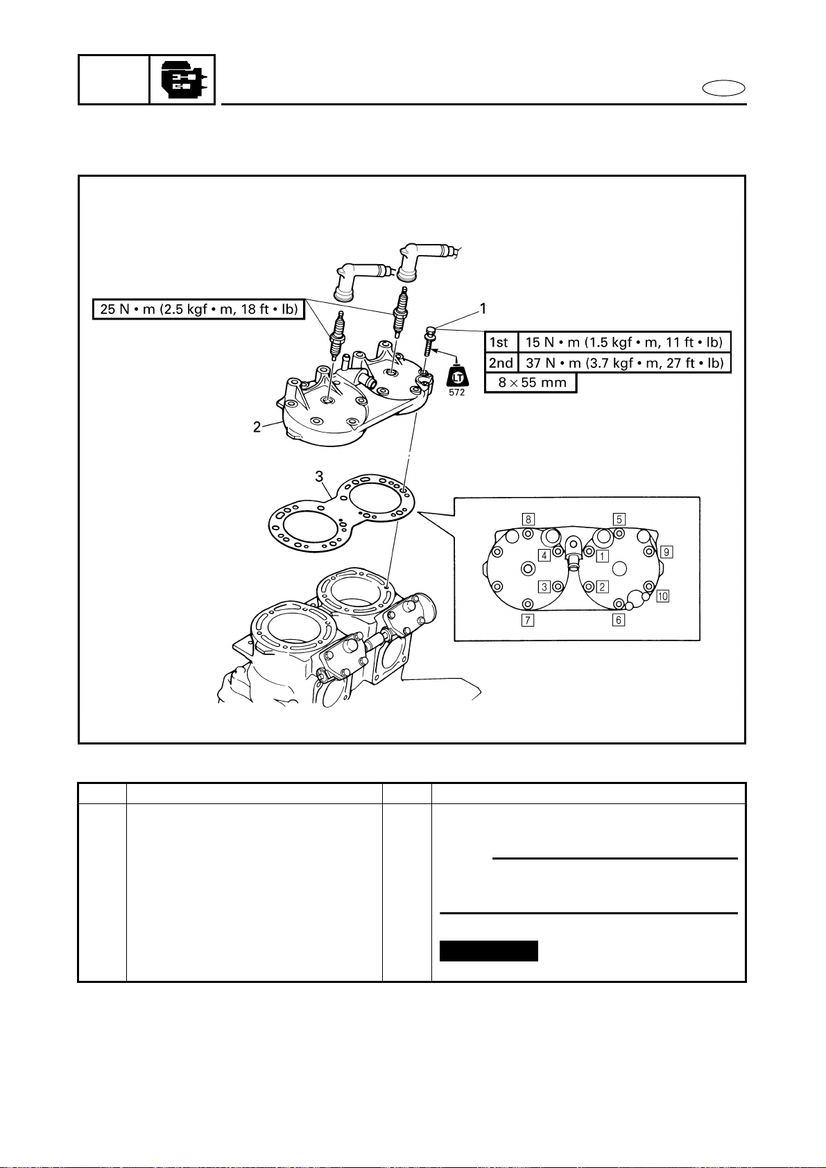
5-18
POWR
E
CYLINDER HEAD
CYLINDER HEAD
EXPLODED DIAGRAM
REMOVAL AND INSTALLATION CHART
Step Procedure/Part name Q’ty Service points
CYLINDER HEAD REMOVAL Follow the left “Step” for removal.
Exhaust manifold Refer to “EXHAUST MANIFOLD”.
1 Bolt 10
NOTE:
Tighten the bolts in the proper sequence
as shown and in two stages.
2 Cylinder head 1
3 Gasket 1
Reverse the removal steps for installation.
Not reusable
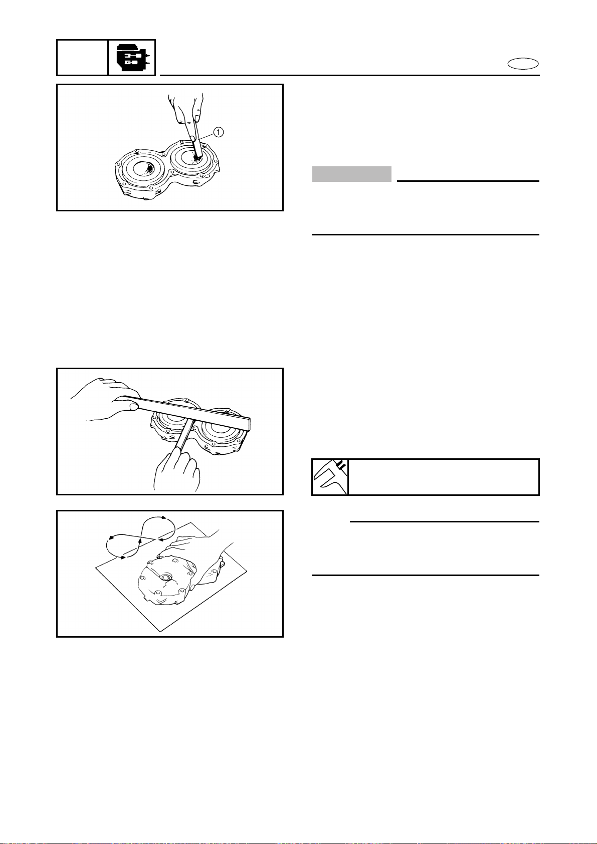
5-19
POWR
E
CYLINDER HEAD
SERVICE POINTS
Cylinder head inspection
1. Eliminate:
● Carbon deposits
(with a rounded scraper 1)
CAUTION:
Do not use a sharp instrument to avoid
damaging or scratching the cylinder head
or spark plug bore threads.
2. Inspect:
● Cylinder head water jacket
Corrosion/mineral deposits → Clean
or replace.
3. Measure:
● Cylinder head warpage
(with a straightedge and thickness
gauge)
Out of specification/score marks →
Resurface.
NOTE:
Place a 400–600 grit wet sandpaper on a
surface plate and resurface the cylinder
head using a figure-eight sanding pattern.
Warpage limit:
0.1 mm (0.004 in)
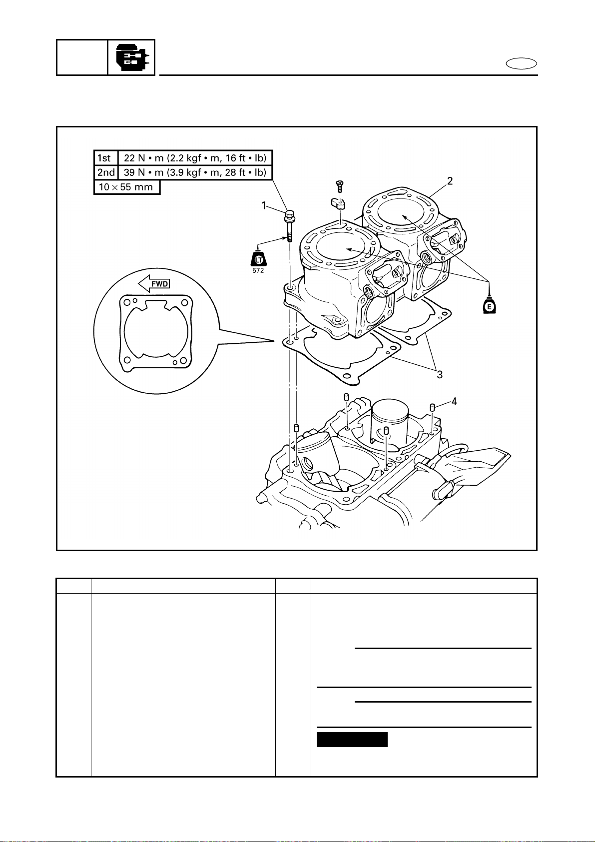
5-20
POWR
E
CYLINDERS
CYLINDERS
EXPLODED DIAGRAM
REMOVAL AND INSTALLATION CHART
Step Procedure/Part name Q’ty Service points
CYLINDER REMOVAL Follow the left “Step” for removal.
YPVS Refer to “YPVS”.
Cylinder head Refer to “CYLINDER HEAD”.
1 Bolt 8
NOTE:
Tighten the bolts in a crisscross pattern
and in two stages.
2 Cylinder 2
NOTE:
Install the original position.
3 Cylinder gasket 2
4 Pin 4
Reverse the removal steps for installation.
Not reusable
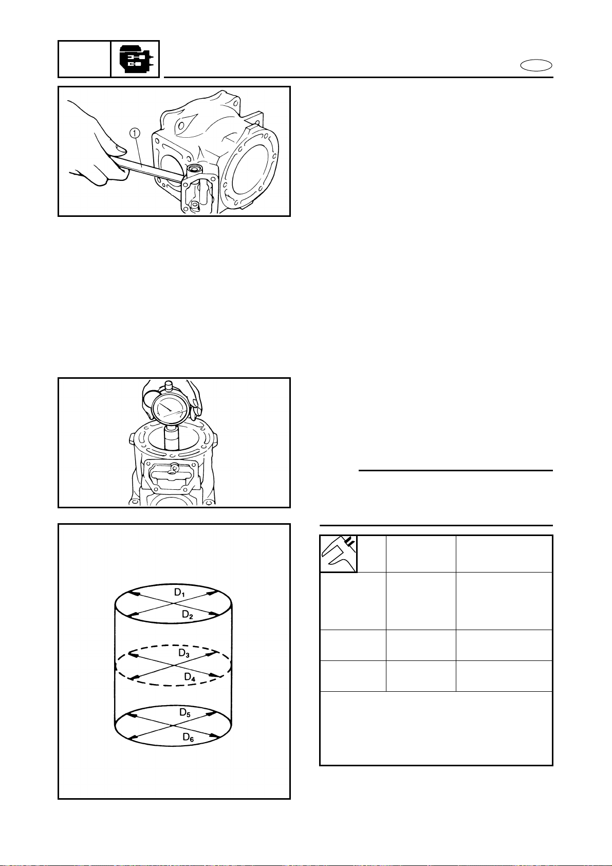
5-21
POWR
E
CYLINDERS
SERVICE POINTS
Cylinder inspection
1. Eliminate:
● Carbon deposits
(with a rounded scraper 1)
2. Inspect:
● Cylinder water jacket
Corrosion/mineral deposits → Clean
or replace.
● Cylinder inner surface
Score marks → Replace.
3. Measure:
● Cylinder bore “D”
(with a cylinder gauge)
Out of specification → Replace cylin-
der and piston as a set.
NOTE:
Measure the cylinder bore in parallel and at
a right angle to the crankshaft. Then, aver-
age the measurements.
Standard Limit
Cylinder
bore “D”
80.000–
80.018 mm
(3.1496–
3.1503 in)
Original cylinder
bore + 0.04 mm
(0.0016 in)
Taper “T” —
0.08 mm
(0.003 in)
Out of
round “R”
—
0.05 mm
(0.002 in)
D = Maximum (D
1
–D
6
)
T = (Maximum D
1
or D
2
) – (Maximum D
5
or D
6
)
R = (Maximum D
1
, D
3
or D
5
) – (Minimum
D
2
, D
4
or D
6
)
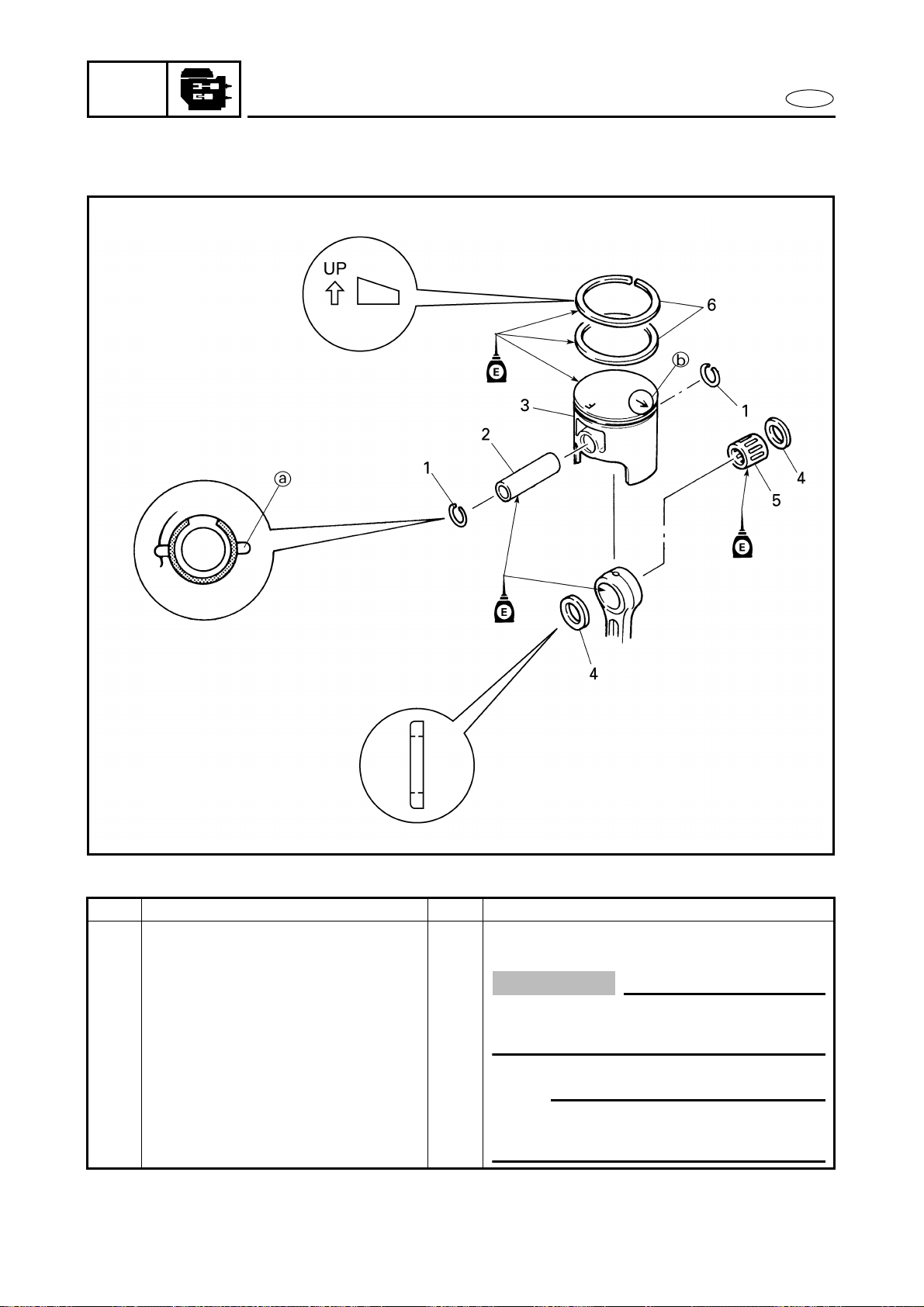
5-22
POWR
E
PISTONS
PISTONS
EXPLODED DIAGRAM
REMOVAL AND INSTALLATION CHART
Step Procedure/Part name Q’ty Service points
PISTON REMOVAL Follow the left “Step” for removal.
Cylinders Refer to “CYLINDERS”.
1 Piston pin clip 2
CAUTION:
Do not align the open end of the clip
with the piston pin slot a.
2 Piston pin 1
3 Piston 1
NOTE:
Make sure that the arrow b faces
towards the exhaust side.
4 Washer 2
5-23
POWR
E
EXPLODED DIAGRAM
Step Procedure/Part name Q’ty Service points
5 Bearing 1
6 Piston ring 2
CAUTION:
Align each end gap with its respective
locating pin.
Reverse the removal steps for installation.
PISTONS
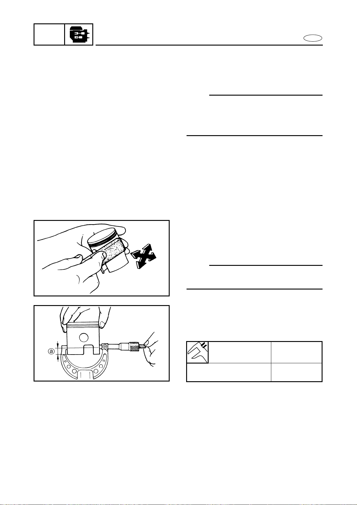
5-24
POWR
E
PISTONS
SERVICE POINTS
Piston pin clip removal and installation
1. Remove and install:
● Piston pin clip
NOTE:
Before removing or installing the piston pin
clip, cover the crankcase opening with a
clean rag to prevent the piston pin clip from
falling into the crankcase.
Piston inspection
1. Eliminate:
● Carbon deposits
(from the piston crown and piston
ring grooves)
2. Inspect:
● Piston wall
Score marks → Repair with 600–800
grit wet sandpaper or replace.
NOTE:
Lightly sand the piston wall in a crisscross
pattern.
3. Measure:
● Piston skirt diameter
(with a micrometer)
Out of specification → Replace.
Piston diameter Distance a
79.899–79.914 mm
(3.1456–3.1462 in)
22 mm
(0.87 in)
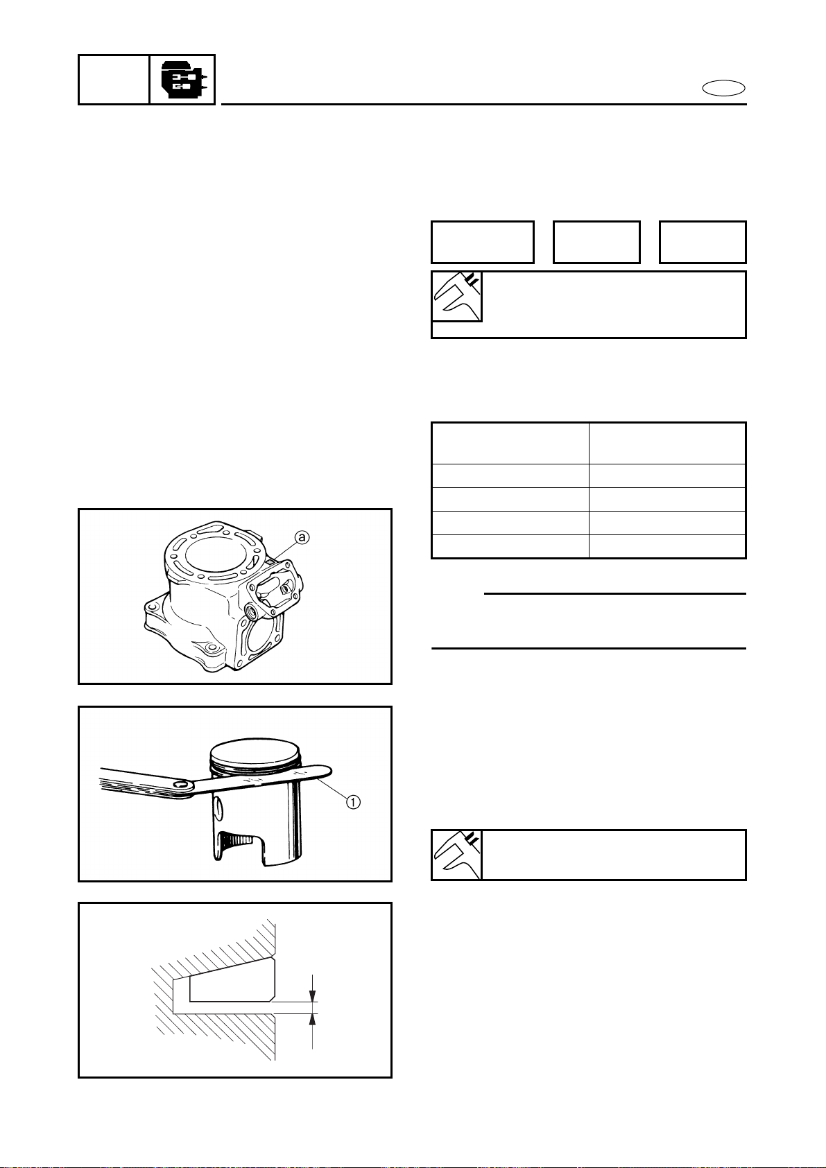
5-25
POWR
E
PISTONS
4. Calculate:
● Piston-to-cylinder clearance
Out of specification → Replace the
piston, piston rings and cylinder as a
set.
Cylinder and piston combination
Select the appropriate piston to match the
cylinder size by the table as follows.
NOTE:
New cylinder bore size = 80.000 + a/1,000
Example: a = 12 → 80.012 mm.
PISTON
CLEARANCE
=
CYLINDER
BORE
–
PISTON
DIAMETER
Piston-to-cylinder clearance:
0.100–0.105 mm
(0.0039–0.0041 in)
Cylinder size
indication a
Piston color mark
0–5 Red
6–10 Orange
11–15 Green
16–18 Purple
Piston ring inspection
1. Measure:
● Side clearance
(with a thickness gauge 1)
Out of specification → Replace the
piston and piston rings as a set.
Side clearance:
0.03–0.05 mm (0.001–0.002 in)
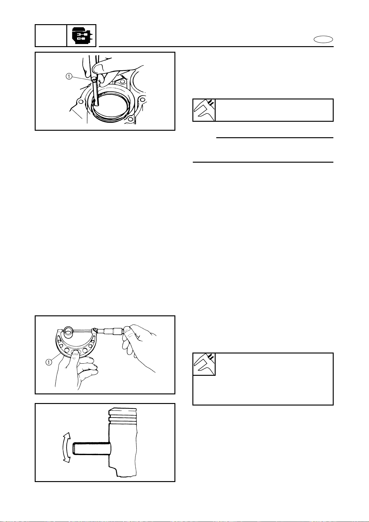
5-26
POWR
E
PISTONS
2. Measure:
● End gap
(with a thickness gauge 1)
Out of specification → Replace the
piston rings as a set.
NOTE:
Push the piston ring into the cylinder with
the piston crown.
End gap:
0.30–0.45 mm (0.012–0.018 in)
Piston pin and bearing inspection
1. Inspect:
● Piston pins
● Bearings
Signs of heat discoloration → Replace.
2. Measure:
● Piston pin outside diameter
(with a micrometer 1)
Out of specification → Replace.
3. Check:
● Piston pin-to-piston free play
(with the piston pin in the piston as
shown)
Free play → Replace the piston pin,
piston or both.
Piston pin outside diameter:
Standard:
21.995–22.000 mm
(0.8659–0.8661 in)
Limit:
21.990 mm (0.8657 in)
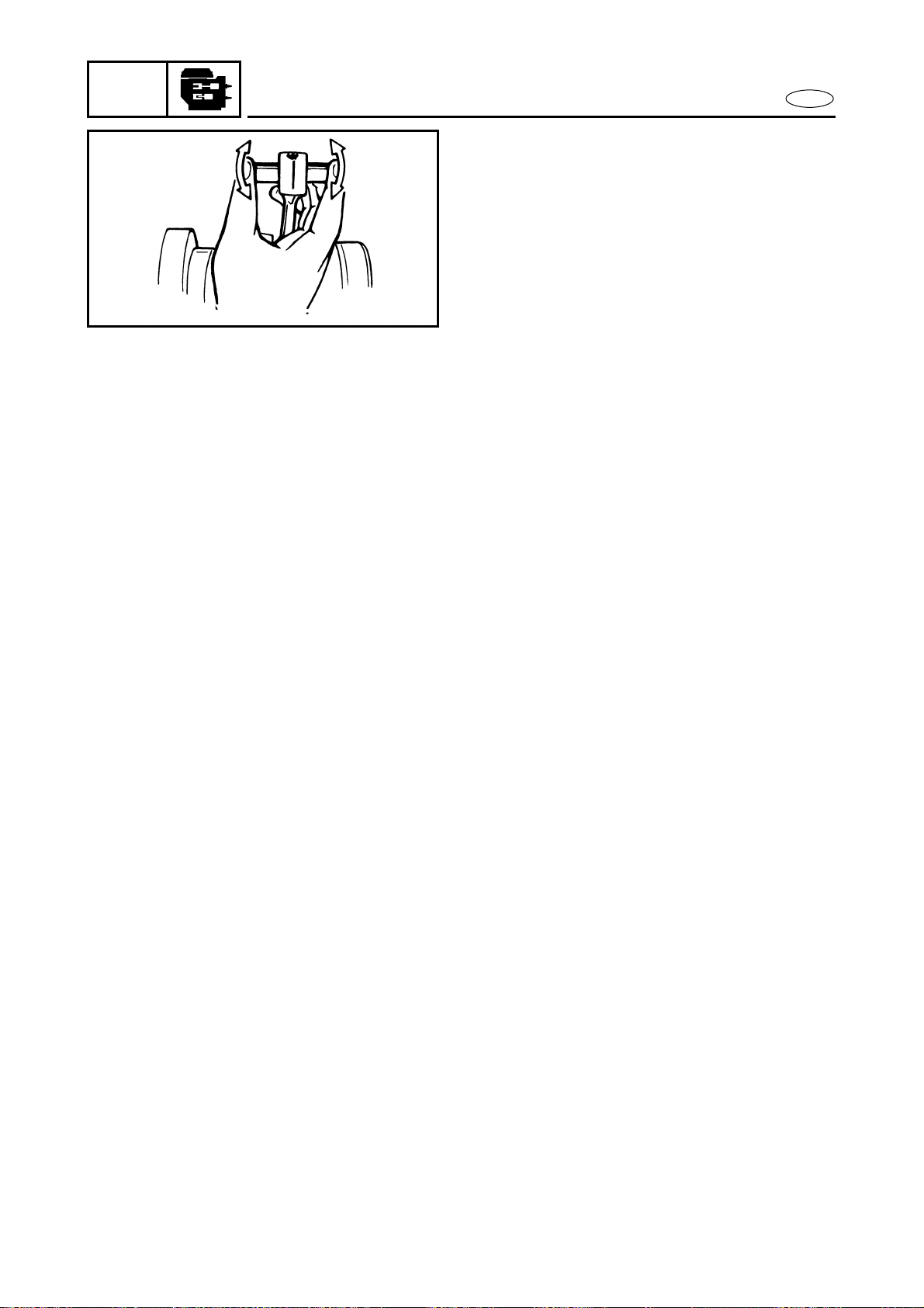
5-27
POWR
E
PISTONS
4. Check:
● Piston pin-to-small end bearing-to-
connecting rod free play
(at the small end of the connecting
rod as shown)
Free play/small end wear → Replace
the piston pin, connecting rod, or
small end bearing.
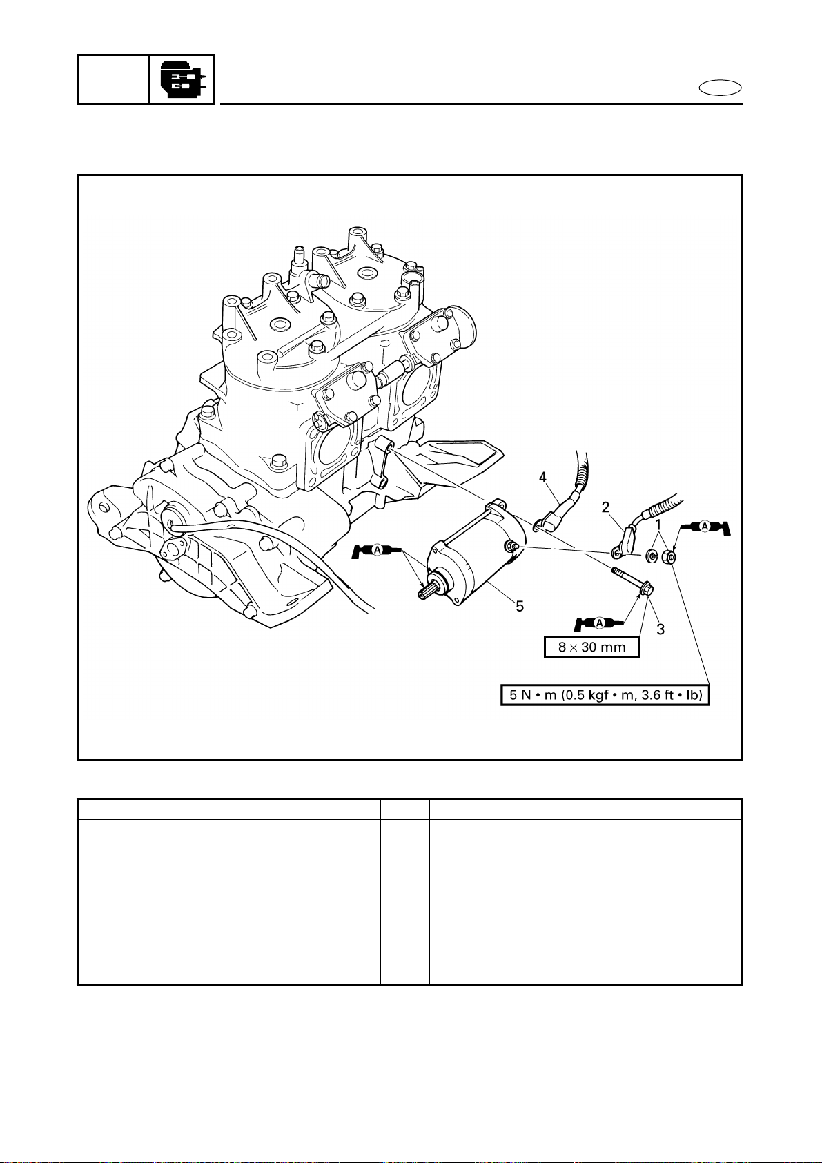
5-28
POWR
E
STARTER MOTOR
STARTER MOTOR
EXPLODED DIAGRAM
REMOVAL AND INSTALLATION CHART
Step Procedure/Part name Q’ty Service points
STARTER MOTOR REMOVAL Follow the left “Step” for removal.
Engine unit Refer to “ENGINE UNIT”.
1 Nut/washer 1/1
2 Starter motor lead 1
3 Bolt 2
4 Battery negative lead 1
5 Starter motor 1
Reverse the removal steps for installation.
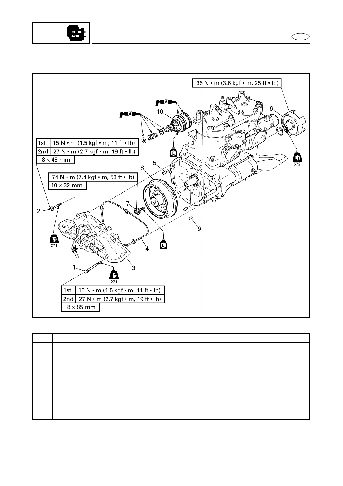
5-29
POWR
E
FLYWHEEL MAGNETO
FLYWHEEL MAGNETO
EXPLODED DIAGRAM
REMOVAL AND INSTALLATION CHART
Step Procedure/Part name Q’ty Service points
FLYWHEEL MAGNETO
REMOVAL
Follow the left “Step” for removal.
Engine unit Refer to “ENGINE UNIT”.
Oil pump Refer to “OIL PUMP” in chapter 4.
1 Bolt 2
2 Bolt 6
3 Generator cover 1
4 Packing 1
5 Pin 2
5-30
POWR
E
FLYWHEEL MAGNETO
EXPLODED DIAGRAM
Step Procedure/Part name Q’ty Service points
6 Drive coupling 1
7 Bolt 1
8 Flywheel magneto 1
9 Woodruff key 1
10 Starter clutch assembly 1
Reverse the removal steps for installation.
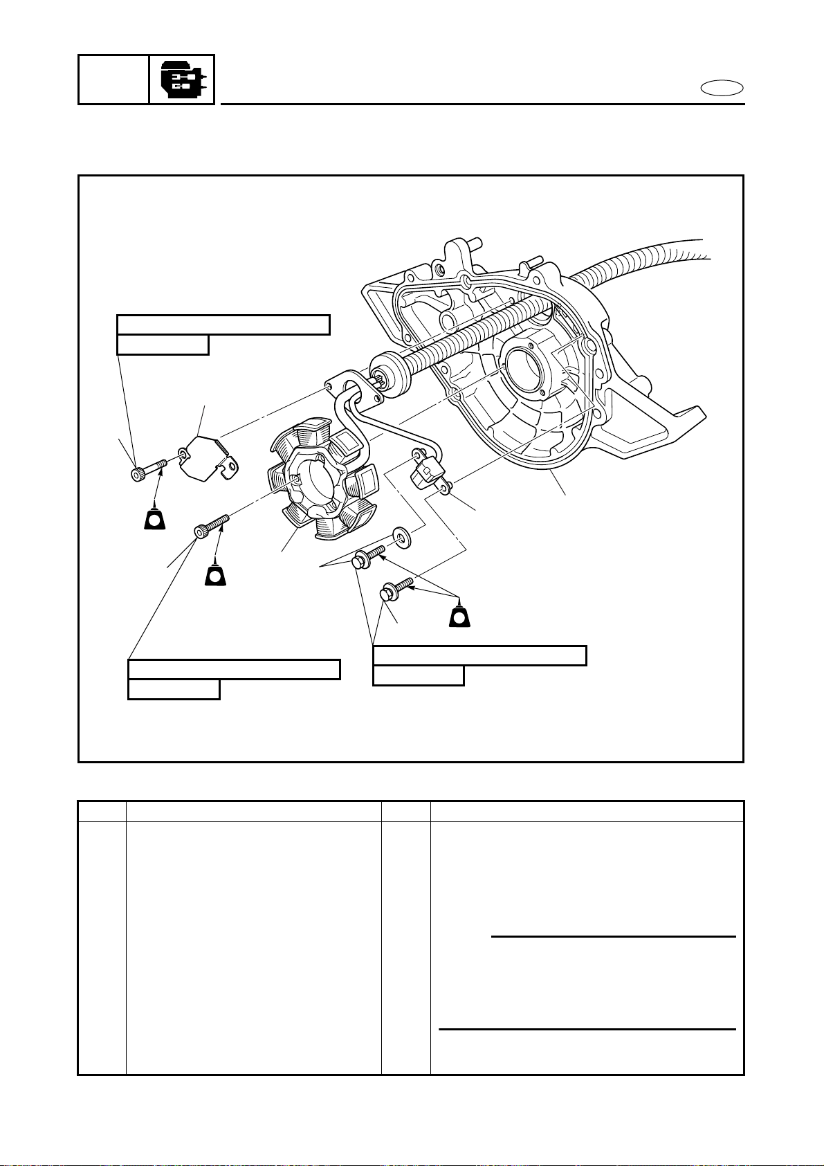
5-31
POWR
E
FLYWHEEL MAGNETO
EXPLODED DIAGRAM
REMOVAL AND INSTALLATION CHART
Step Procedure/Part name Q’ty Service points
GENERATOR COVER
DISASSEMBLY
Follow the left “Step” for disassembly.
1 Bolt 3
2 Stator coil 1
3 Bolt 2
4 Cable holder 1
NOTE:
This washer holds the pickup coil lead.
Make sure to not pinch the lead between
the projection and the washer when
installing the bolt.
5 Bolt/washer 1/1
6 Bolt 1
7 Pickup coil 1
8 Generator cover 1
Reverse the disassembly steps for
assembly.
6 × 14 mm
14 N • m (1.4 kgf • m, 10 ft • Ib)
5 × 14 mm
5 N • m (0.5 kgf • m, 3.6 ft • Ib)
6 × 30 mm
14 N • m (1.4 kgf • m, 10 ft • Ib)
3
LTLT
LT
242242
1
5
6
LTLT
LT
242242
2
4
7
LTLT
LT
242242
8
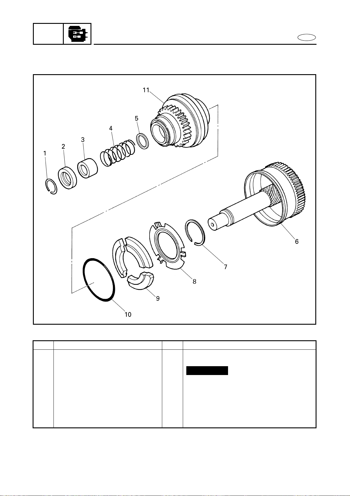
5-32
POWR
E
FLYWHEEL MAGNETO
EXPLODED DIAGRAM
REMOVAL AND INSTALLATION CHART
Step Procedure/Part name Q’ty Service points
STARTER CLUTCH
DISASSEMBLY
Follow the left “Step” for disassembly.
1 Clip 1
2 Clip stopper 1
3 Spring seat 1
4 Spring 1
5 Washer 1
6 Idle gear 1
7 Circlip 1
Not reusable
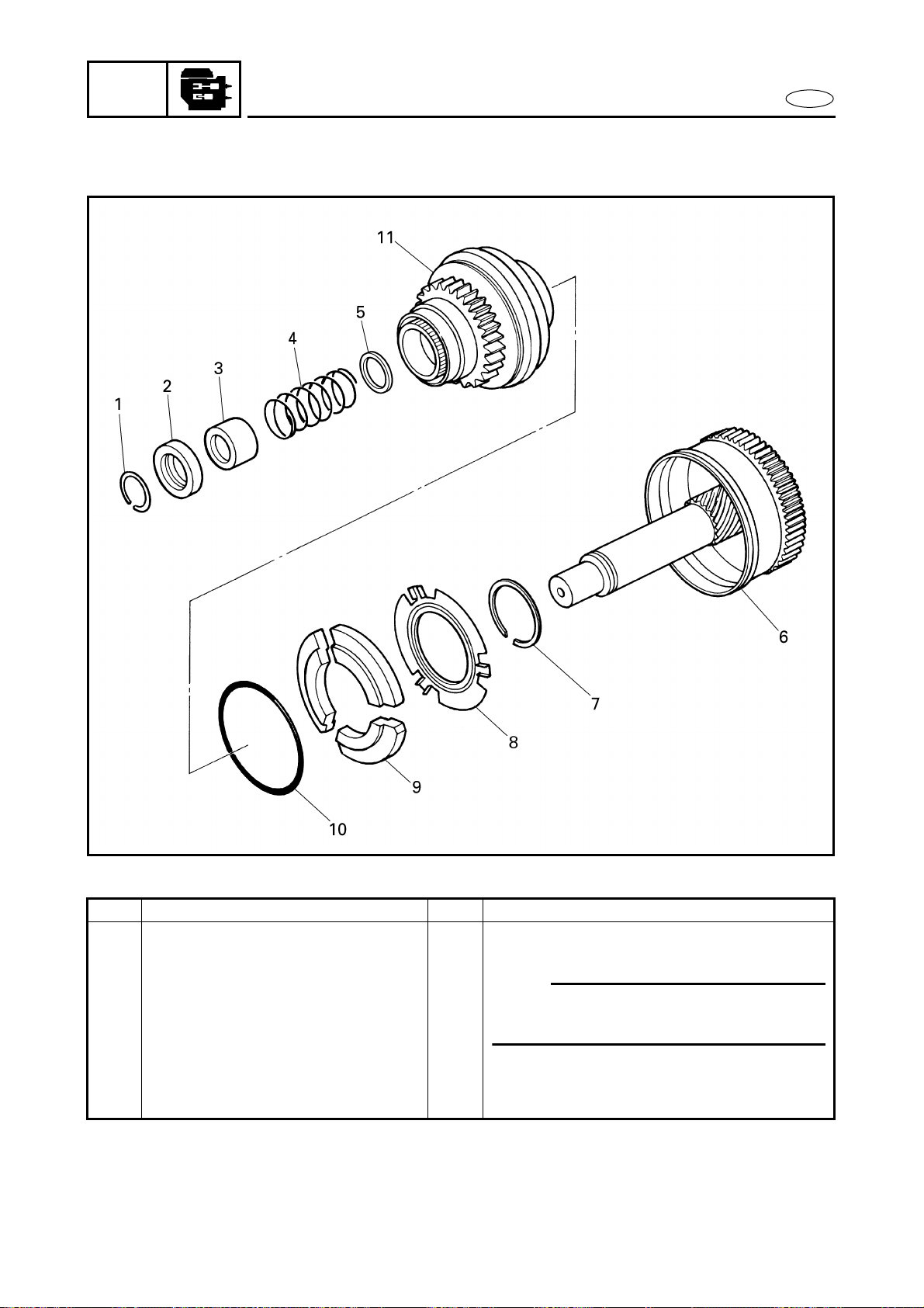
5-33
POWR
E
FLYWHEEL MAGNETO
EXPLODED DIAGRAM
Step Procedure/Part name Q’ty Service points
8 Plate 1
9 Weight 3
10 Spring ring 1
NOTE:
Install the spring ring after installing the
weights, plate and circlip.
11 Pinion gear 1
Reverse the disassembly steps for
assembly.
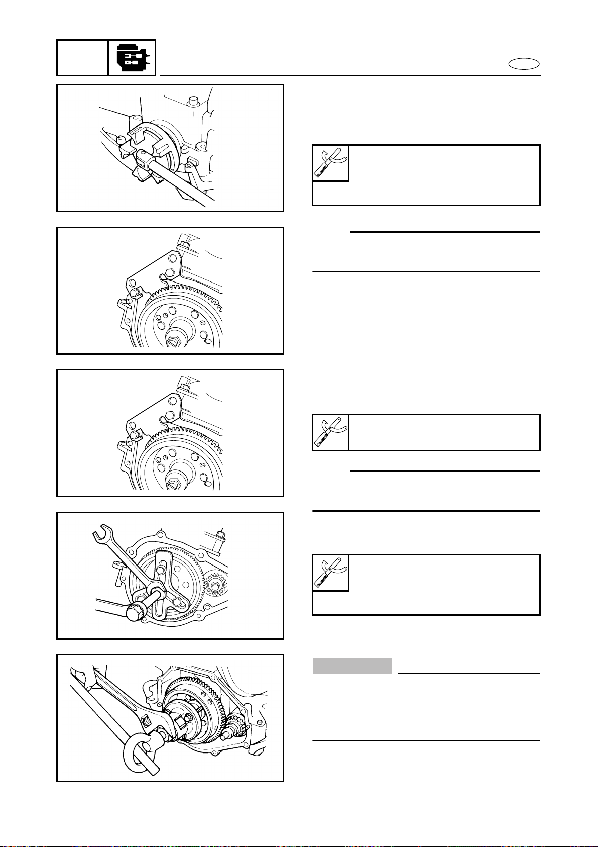
5-34
POWR
E
FLYWHEEL MAGNETO
SERVICE POINTS
Drive coupling removal and installation
1. Remove:
● Drive coupling
NOTE:
Install the drive coupling with the same
special tools that were used for removal.
Coupler wrench:
YW-06551/90890-06551
Flywheel holder:
YW-06550/90890-06550
Flywheel magneto removal and installation
1. Remove:
● Flywheel magneto bolt
NOTE:
Install the bolt with the same special tool
that was used for removal.
2. Remove:
● Flywheel magneto
Å For USA and Canada
ı For worldwide
CAUTION:
To prevent damage to the engine or tools,
screw in the flywheel puller set bolts
evenly and completely so that the puller
plate is parallel to the flywheel magneto.
Flywheel holder:
YW-06550/90890-06550
Flywheel puller:
YB-06117/90890-06521
Set bolt:
M8 × 60 mm
Å
ı
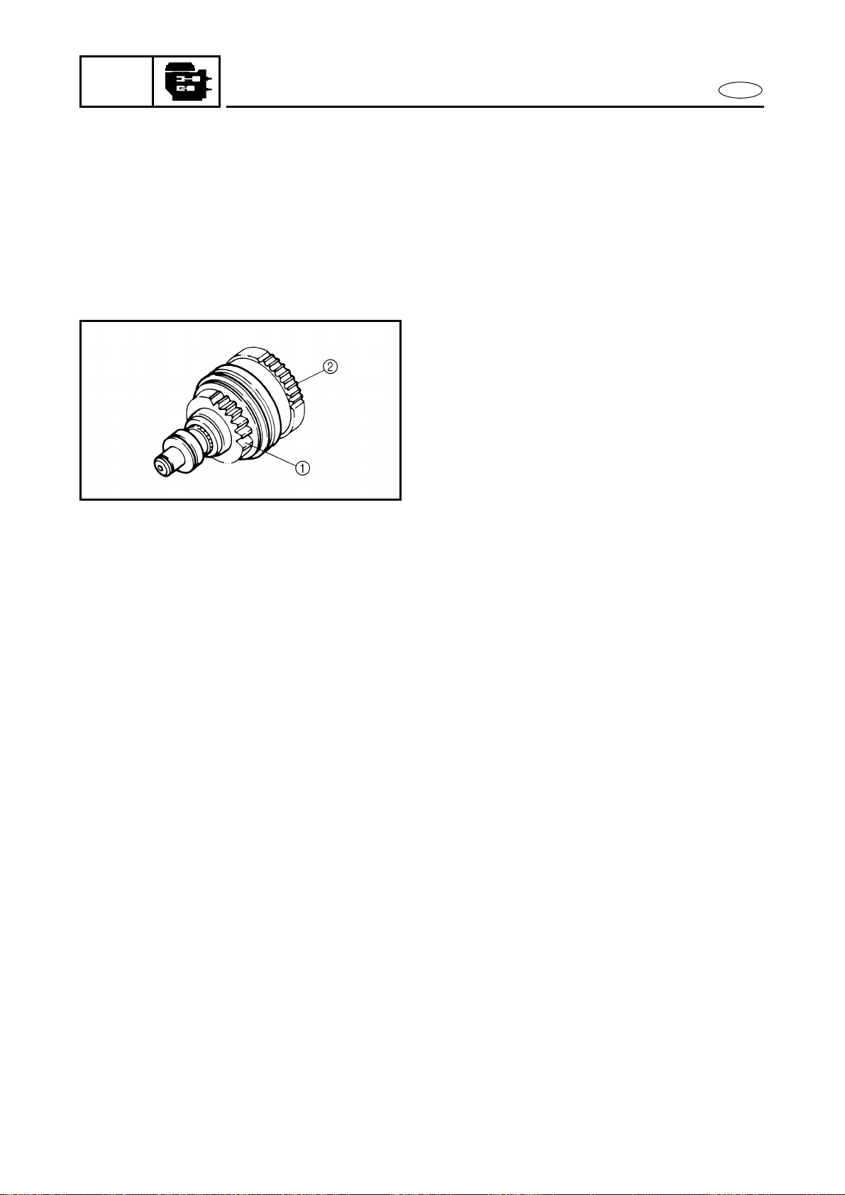
5-35
POWR
E
FLYWHEEL MAGNETO
Drive coupling inspection
1. Inspect:
● Drive coupling
Damage/wear → Replace.
Flywheel magneto inspection
1. Inspect:
● Ring gear
Damage/wear → Replace.
Starter clutch assembly inspection
1. Inspect:
● Pinion gear 1
● Idle gear 2
Damage/wear → Replace.
2. Check:
● Gear movement
Rough movement → Replace the
defective part(s).
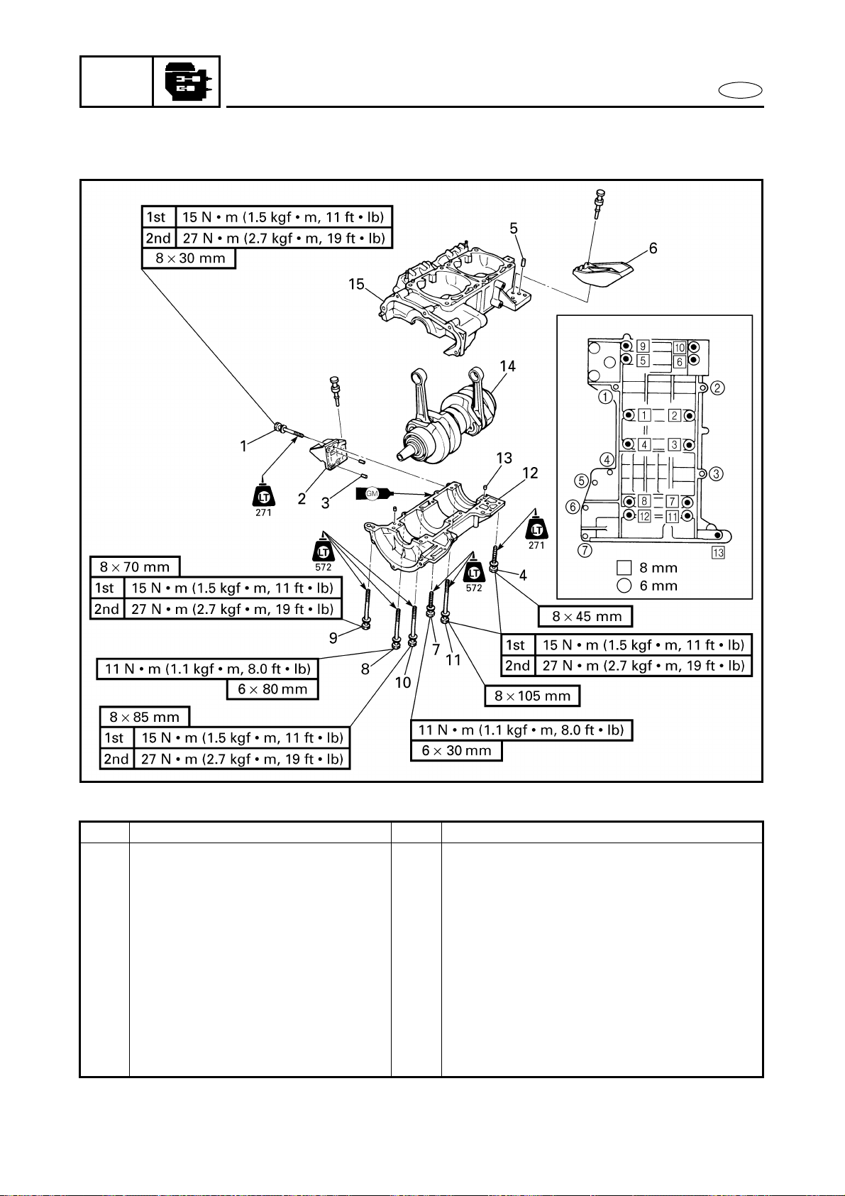
5-36
POWR
E
CRANKCASE
CRANKCASE
EXPLODED DIAGRAM
REMOVAL AND INSTALLATION CHART
Step Procedure/Part name Q’ty Service points
CRANKCASE DISASSEMBLY Follow the left “Step” for disassembly.
Pistons Refer to “PISTONS”.
Starter motor Refer to “STARTER MOTOR”.
Generator cover Refer to “FLYWHEEL MAGNETO”.
1 Bolt 3
2 Mount bracket 1 1
3 Pin 2
4 Bolt 3
5 Pin 2
6 Mount bracket 2 1
7 Bolt 4

5-37
POWR
E
EXPLODED DIAGRAM
Step Procedure/Part name Q’ty Service points
8 Bolt 3
NOTE:
Tighten the bolts in sequence as shown.
9 Bolt 1
10 Bolt 10
11 Bolt 2
12 Lower crankcase 1
13 Pin 2
14 Crankshaft assembly 1
15 Upper crankcase 1
Reverse the disassembly steps for
assembly.
CRANKCASE
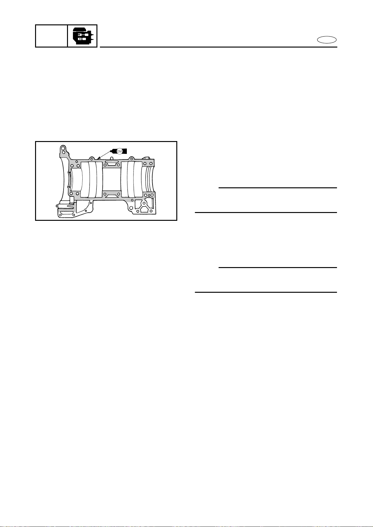
5-38
POWR
E
CRANKCASE
SERVICE POINTS
Crankcase inspection
1. Inspect:
● Mating surfaces
Scratches → Replace the crankcase.
● Crankcase
Cracks/damage → Replace.
Crankcase installation
1. Apply:
● Gasket Maker
®
(onto the crankcase mating surfaces)
NOTE:
Before applying Gasket Maker
®
,
clean the
crankcase mating surfaces.
2. Check:
● Crankshaft
Rough movement → Recheck.
NOTE:
Make sure that the crankshaft rotates
smoothly after installing it.
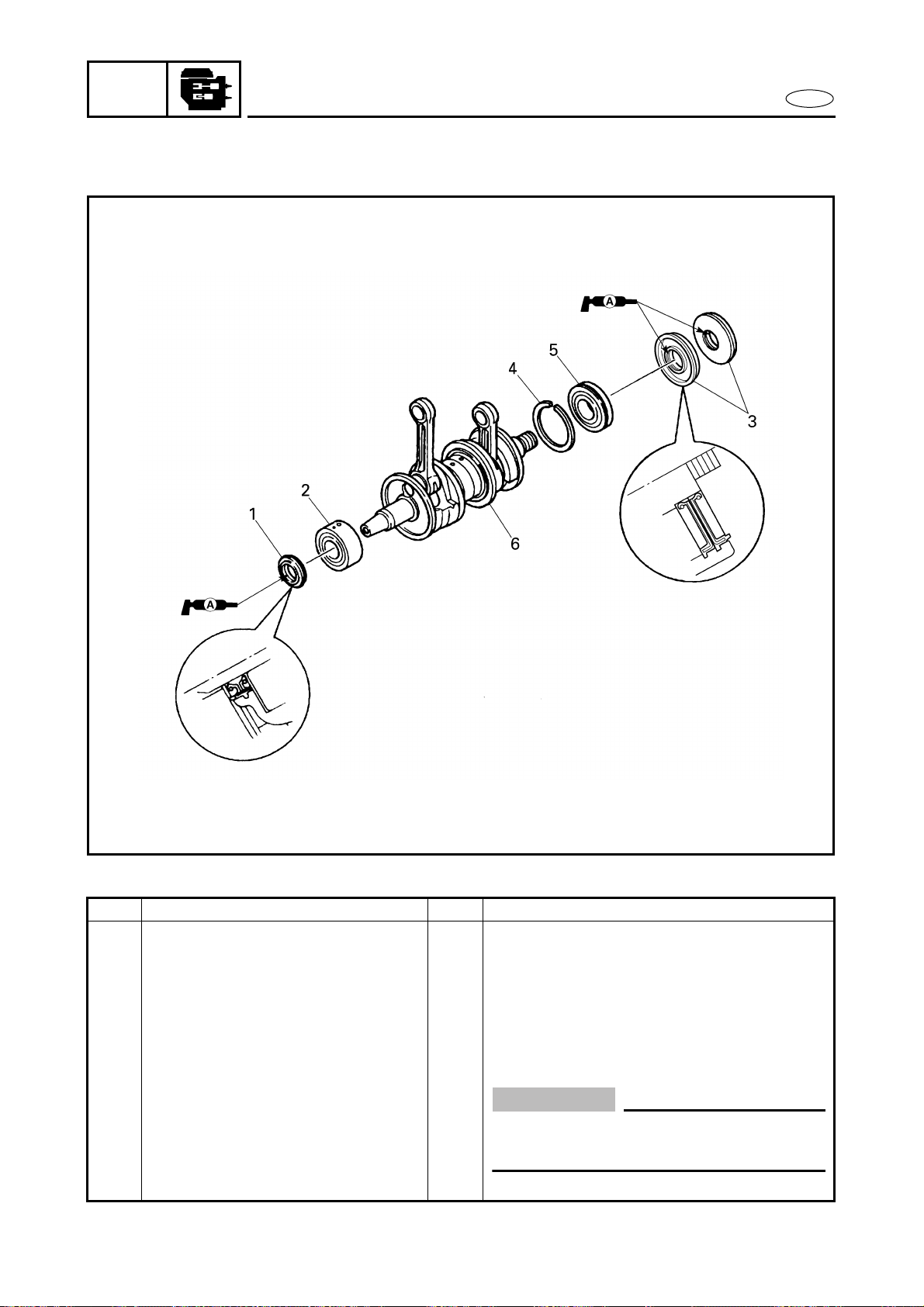
5-39
POWR
E
CRANKSHAFT
CRANKSHAFT
EXPLODED DIAGRAM
REMOVAL AND INSTALLATION CHART
Step Procedure/Part name Q’ty Service points
CRANKSHAFT REMOVAL Follow the left “Step” for removal.
Crankcase Refer to “CRANKCASE”.
1 Oil seal 1
2 Bearing 1
3 Oil seal 2
4 Bearing clip 1
5 Bearing 1
6 Crankshaft 1
CAUTION:
Install the bearing locating pins into the
grooves in the crankcase body.
Reverse the removal steps for installation.
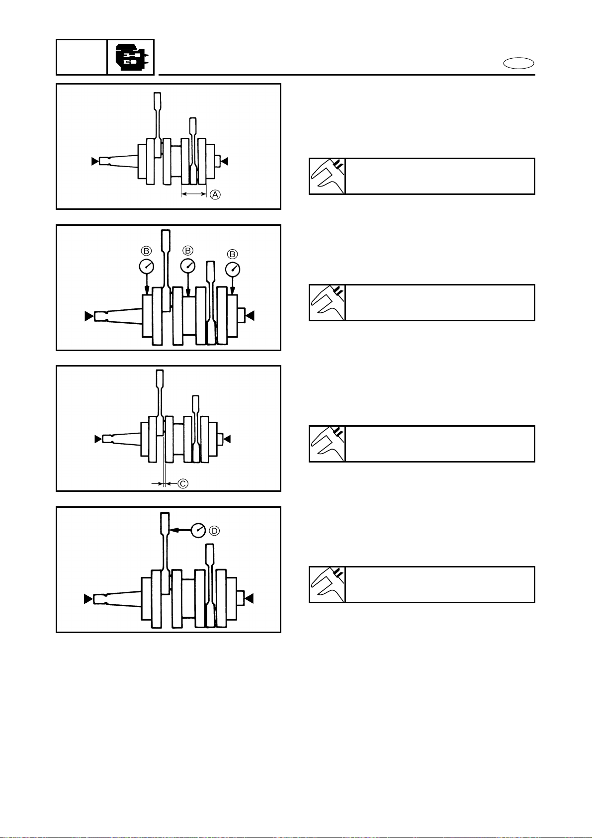
5-40
POWR
E
CRANKSHAFT
SERVICE POINTS
Crankshaft inspection
1. Measure:
● Crank width A
Out of specification → Replace.
Crank width:
72.95–73.00 mm (2.872–2.874 in)
2. Measure:
● Deflection B
(with a dial gauge)
Out of specification → Replace.
Max. deflection:
0.05 mm (0.002 in)
3. Measure:
● Big end side clearance C
(with a thickness gauge)
Out of specification → Replace.
Big end side clearance:
0.25–0.75 mm (0.010–0.030 in)
4. Measure:
● Small end free play D
(with a dial gauge)
Out of specification → Replace.
Small end free play:
2.0 mm (0.08 in)
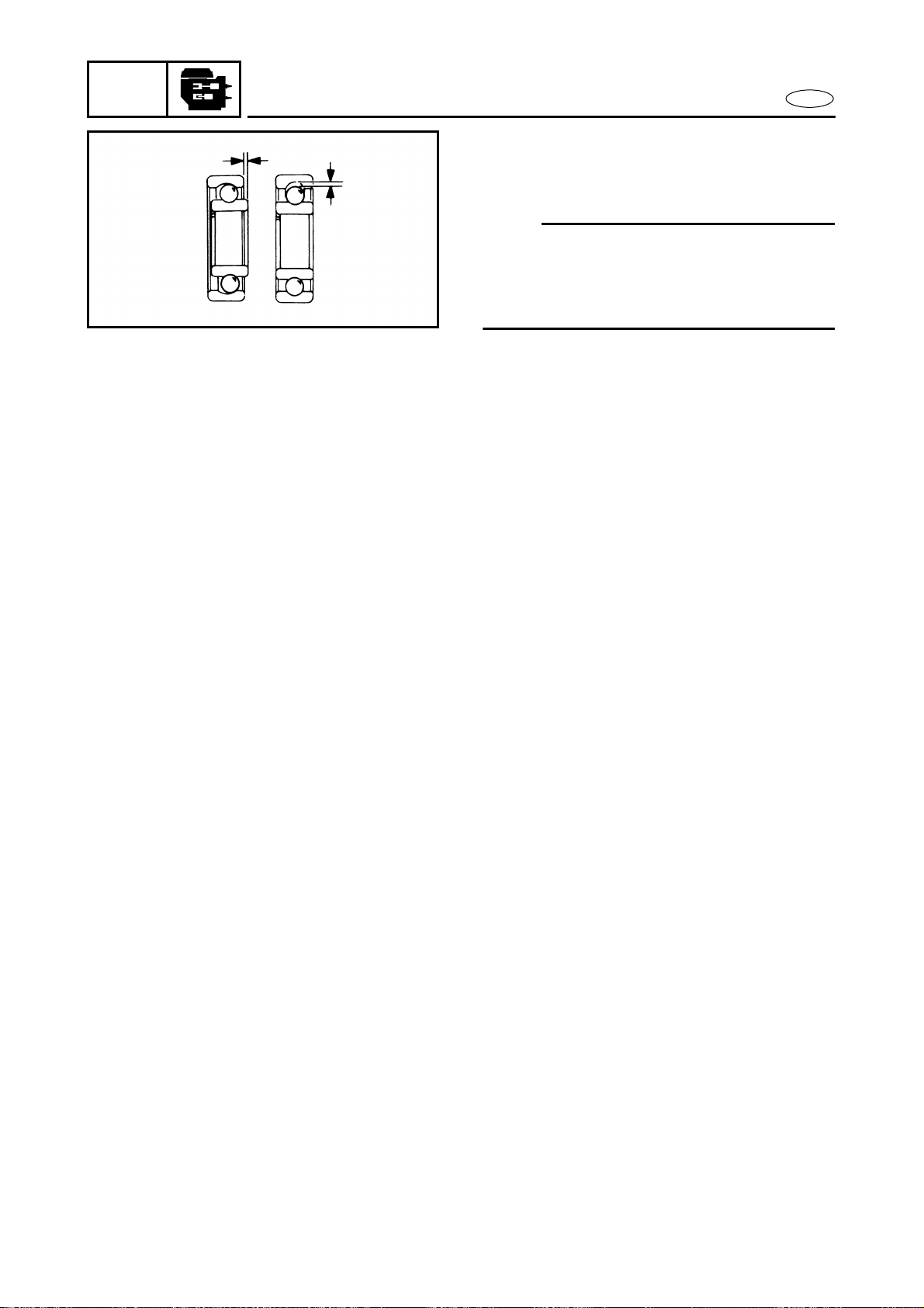
5-41
POWR
E
CRANKSHAFT
5. Inspect:
● Bearings
Damage/pitting → Replace.
NOTE:
● Before inspection, thoroughly clean the
bearings.
● Immediately after inspection, lubricate the
bearings to prevent rust.
6. Inspect:
● Oil seals
Damage/wear → Replace.

E
1
2
3
4
5
6
7
8
9
JET
PUMP
CHAPTER 6
JET PUMP UNIT
JET PUMP UNIT ............................................................................................. 6-1
EXPLODED DIAGRAM............................................................................. 6-1
REMOVAL AND INSTALLATION CHART ............................................... 6-1
NOZZLE DEFLECTOR AND NOZZLE RING................................................... 6-4
EXPLODED DIAGRAM............................................................................. 6-4
REMOVAL AND INSTALLATION CHART ............................................... 6-4
IMPELLER DUCT, IMPELLER HOUSING, AND INTAKE DUCT.................... 6-5
EXPLODED DIAGRAM............................................................................. 6-5
REMOVAL AND INSTALLATION CHART ............................................... 6-5
IMPELLER DUCT AND DRIVE SHAFT........................................................... 6-7
EXPLODED DIAGRAM............................................................................. 6-7
REMOVAL AND INSTALLATION CHART ............................................... 6-7
SERVICE POINTS ..................................................................................... 6-9
Drive shaft removal........................................................................... 6-9
Impeller inspection ......................................................................... 6-10
Drive shaft inspection ..................................................................... 6-10
Drive shaft installation.................................................................... 6-10
TRANSOM PLATE AND HOSES.................................................................. 6-13
EXPLODED DIAGRAM........................................................................... 6-13
REMOVAL AND INSTALLATION CHART ............................................. 6-13
SERVICE POINTS ................................................................................... 6-15
Bilge strainer inspection................................................................. 6-15
Bilge hose inspection...................................................................... 6-15
BEARING HOUSING..................................................................................... 6-16
EXPLODED DIAGRAM........................................................................... 6-16
REMOVAL AND INSTALLATION CHART ............................................. 6-16
SERVICE POINTS ................................................................................... 6-19
Driven coupling removal and installation..................................... 6-19
Intermediate drive shaft removal .................................................. 6-19
Bearing removal.............................................................................. 6-19
Bearing, driven coupling shaft, and grease hose inspection ...... 6-20
Driven coupling inspection ............................................................ 6-20
Bearing installation ......................................................................... 6-20
Oil seal installation.......................................................................... 6-20
Intermediate housing installation.................................................. 6-21
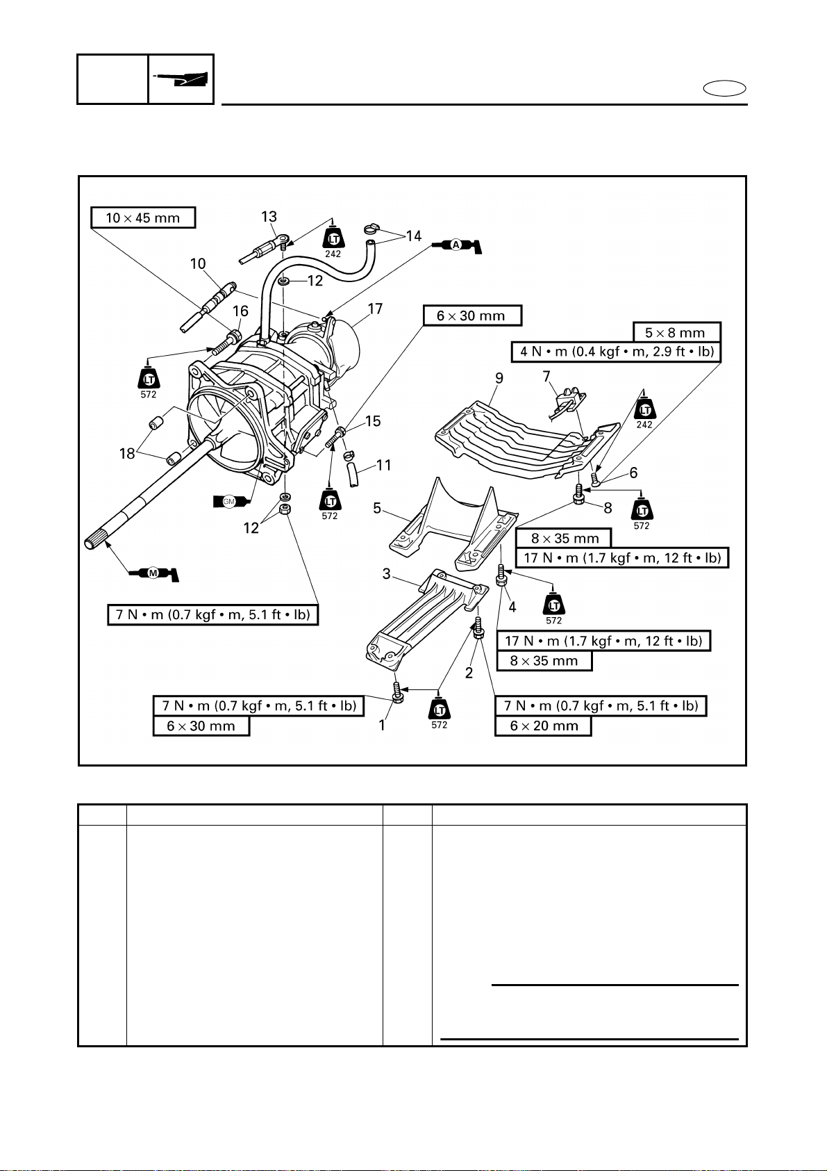
6-1
E
JET
PUMP
JET PUMP UNIT
JET PUMP UNIT
EXPLODED DIAGRAM
REMOVAL AND INSTALLATION CHART
Step Procedure/Part name Q’ty Service points
JET PUMP UNIT REMOVAL Follow the left “Step” for removal.
1 Bolt 2
2 Bolt 2
3 Intake grate 1
4 Bolt 4
5 Intake duct 1
6 Screw 4
7 Speed sensor 1
NOTE:
Route the speed sensor lead between the
jet pump unit and the bilge hose.
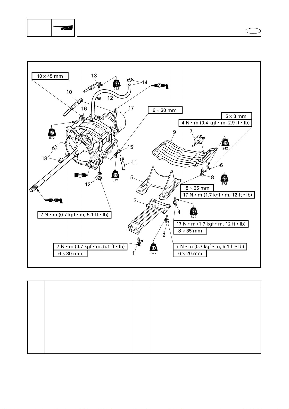
6-2
E
JET
PUMP
JET PUMP UNIT
EXPLODED DIAGRAM
Step Procedure/Part name Q’ty Service points
8 Bolt 4
9 Ride plate 1
10 QSTS cable joint 1
11 Bilge hose 1
12 Nut/washer 1/2
13 Steering cable joint 1
14 Clamp/spout hose 1/1
15 Bolt 1
16 Bolt 4
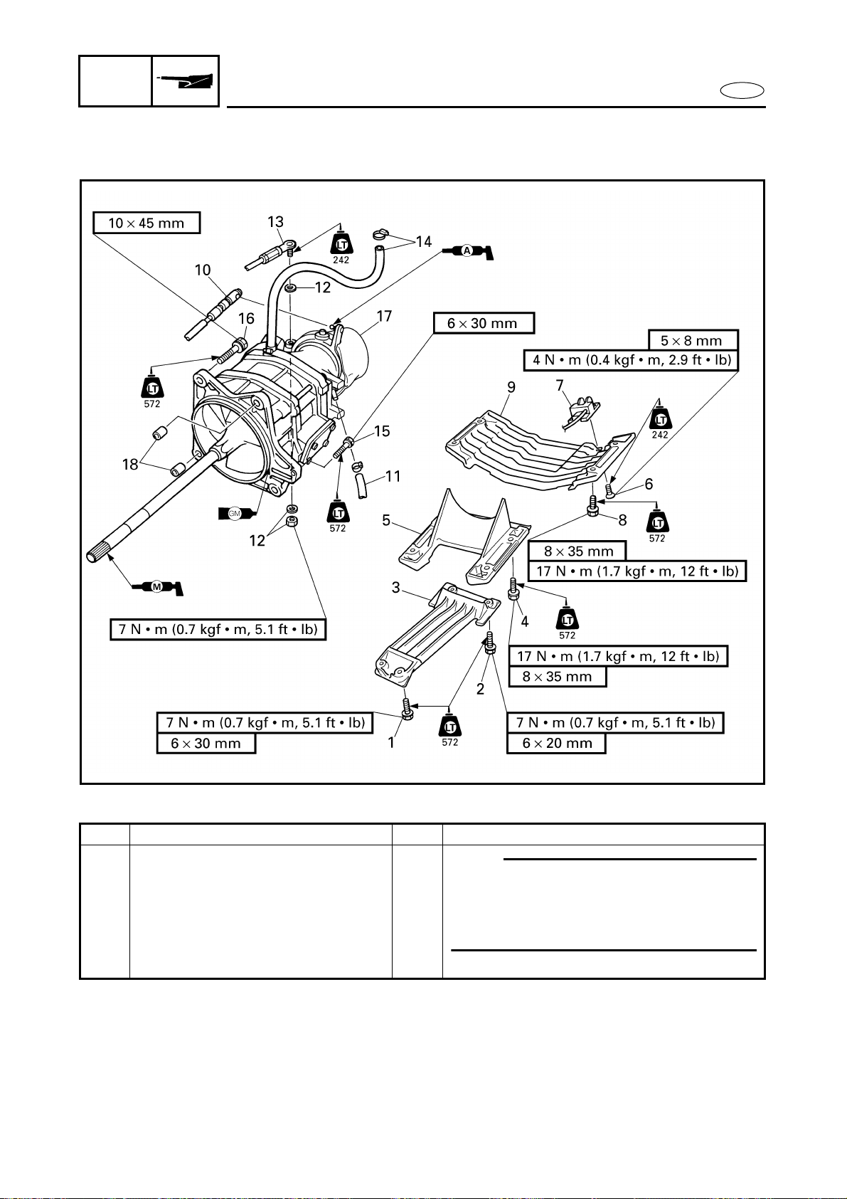
6-3
E
JET
PUMP
JET PUMP UNIT
EXPLODED DIAGRAM
Step Procedure/Part name Q’ty Service points
17 Jet pump unit assembly 1
NOTE:
● Pull the jet pump unit straight back.
● When installing the jet pump unit, align
the drive shaft spline (male) with the
intermediate drive shaft spline (female).
18 Dowel pin 2
Reverse the removal steps for installation.
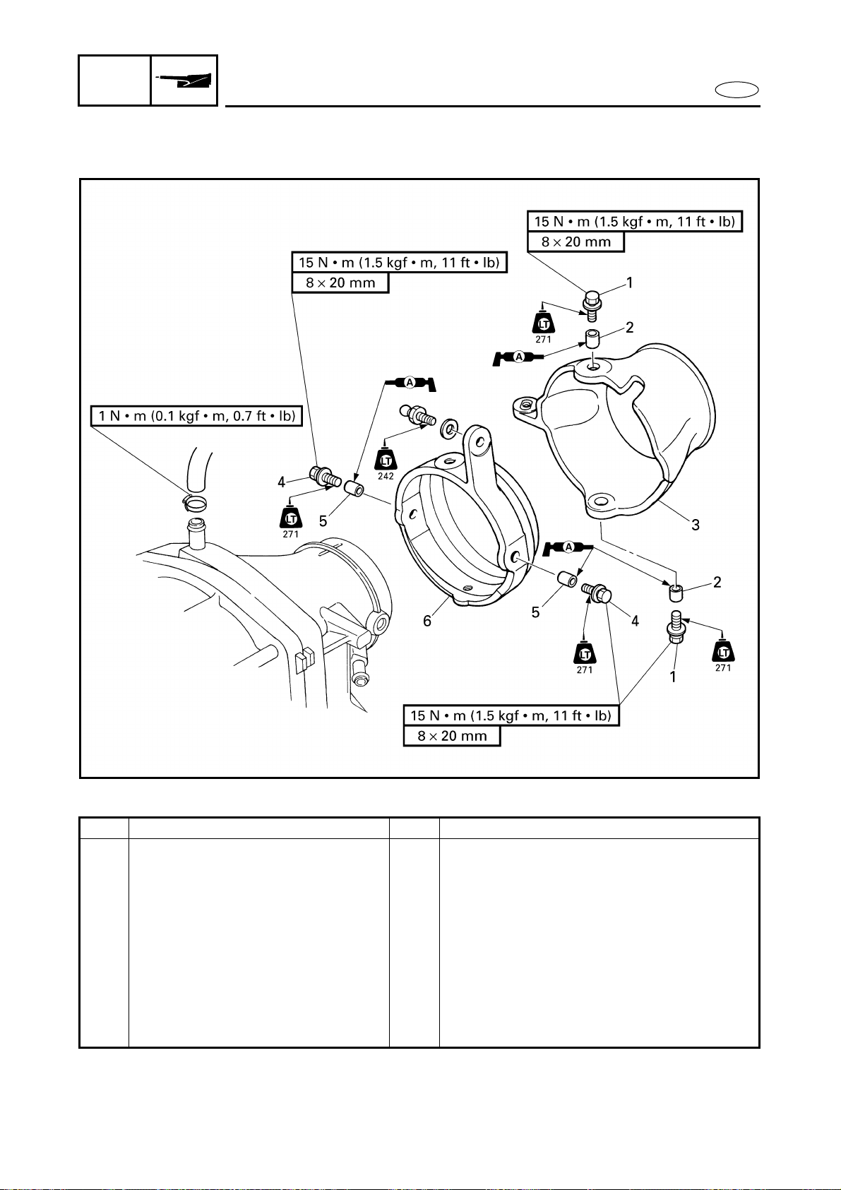
6-4
E
JET
PUMP
NOZZLE DEFLECTOR AND NOZZLE RING
NOZZLE DEFLECTOR AND NOZZLE RING
EXPLODED DIAGRAM
REMOVAL AND INSTALLATION CHART
Step Procedure/Part name Q’ty Service points
NOZZLE DEFLECTOR AND
NOZZLE RING REMOVAL
Follow the left “Step” for removal.
Jet pump unit Refer to “JET PUMP UNIT”.
1 Bolt 2
2 Collar 2
3 Nozzle deflector 1
4 Bolt 2
5 Collar 2
6 Nozzle ring 1
Reverse the removal steps for installation.
6-5
E
JET
PUMP
IMPELLER DUCT, IMPELLER HOUSING,
AND INTAKE DUCT
IMPELLER DUCT, IMPELLER HOUSING, AND INTAKE DUCT
EXPLODED DIAGRAM
REMOVAL AND INSTALLATION CHART
Step Procedure/Part name Q’ty Service points
IMPELLER DUCT AND IMPELLER
HOUSING REMOVAL
Follow the left “Step” for removal.
Nozzle ring Refer to “NOZZLE DEFLECTOR AND
NOZZLE RING”.
1 Bolt 4
2 Nozzle 1
NOTE:
Clean the matching surfaces before
applying the Gasket Maker
®
.
3 Pin 2
4 Impeller duct assembly 1
5 Impeller housing 1
6 Pin 2
6-6
E
JET
PUMP
IMPELLER DUCT, IMPELLER HOUSING,
AND INTAKE DUCT
EXPLODED DIAGRAM
Step Procedure/Part name Q’ty Service points
7 Bolt 4
8 Water inlet cover 1
9 Packing 1
10 Water inlet strainer 1
11 Packing 1
Reverse the removal steps for installation.
6-7
E
JET
PUMP
IMPELLER DUCT AND DRIVE SHAFT
IMPELLER DUCT AND DRIVE SHAFT
EXPLODED DIAGRAM
REMOVAL AND INSTALLATION CHART
*1
: EPNOC grease AP #0
Step Procedure/Part name Q’ty Service points
IMPELLER DUCT AND DRIVE
SHAFT DISASSEMBLY
Follow the left “Step” for disassembly.
1 Impeller 1 Left-hand threads
2 Spacer 1
3 Bolt 3
4 Cap 1
5 O-ring 1
6 Nut 1
7 Washer 1
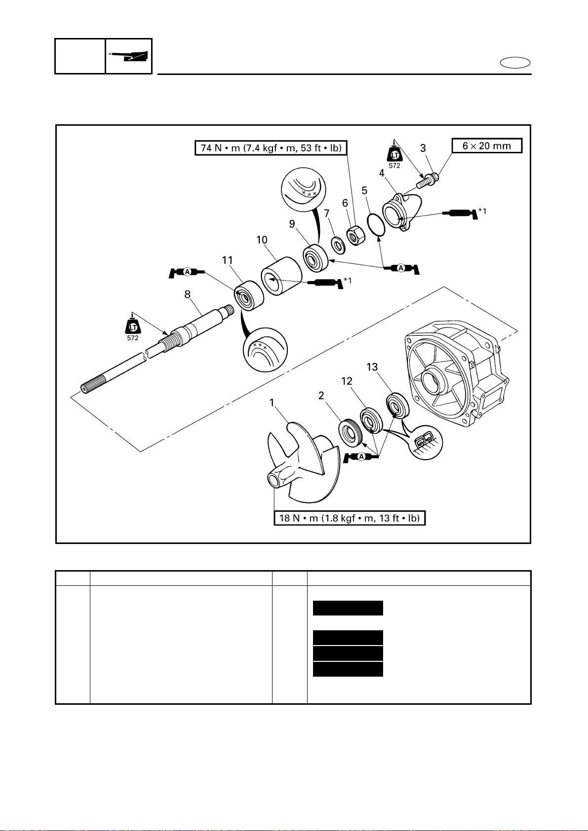
6-8
E
JET
PUMP
IMPELLER DUCT AND DRIVE SHAFT
EXPLODED DIAGRAM
*1
: EPNOC grease AP #0
Step Procedure/Part name Q’ty Service points
8 Drive shaft 1
9 Rear bearing 1
10 Spacer 1
11 Front bearing 1
12 Oil seal 1
13 Oil seal 1
Reverse the disassembly steps for
assembly.
Not reusable
Not reusable
Not reusable
Not reusable
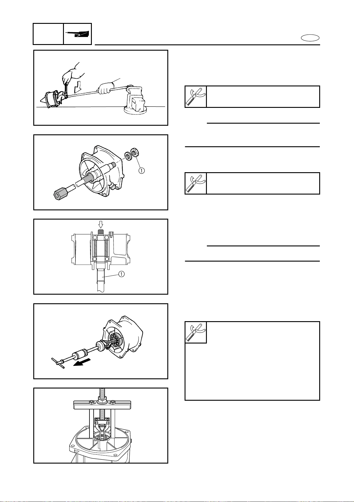
6-9
E
JET
PUMP
IMPELLER DUCT AND DRIVE SHAFT
SERVICE POINTS
Drive shaft removal
1. Remove:
● Impeller
NOTE:
The impeller has left-hand threads. Turn the
impeller clockwise to loosen it.
2. Remove:
● Nut 1
Drive shaft holder:
YB-06151/90890-06519
Drive shaft holder:
YB-06151/90890-06519
3. Remove:
● Drive shaft 1
NOTE:
Remove the drive shaft with a press.
4. Remove:
● Rear bearing
Å For USA and Canada
ı For worldwide
Slide hammer set:
YB-06096
Stopper guide plate:
90890-06501
Bearing puller:
90890-06535
Bearing puller claw 1:
90890-06536
Stopper guide stand:
90890-06538
Å
ı
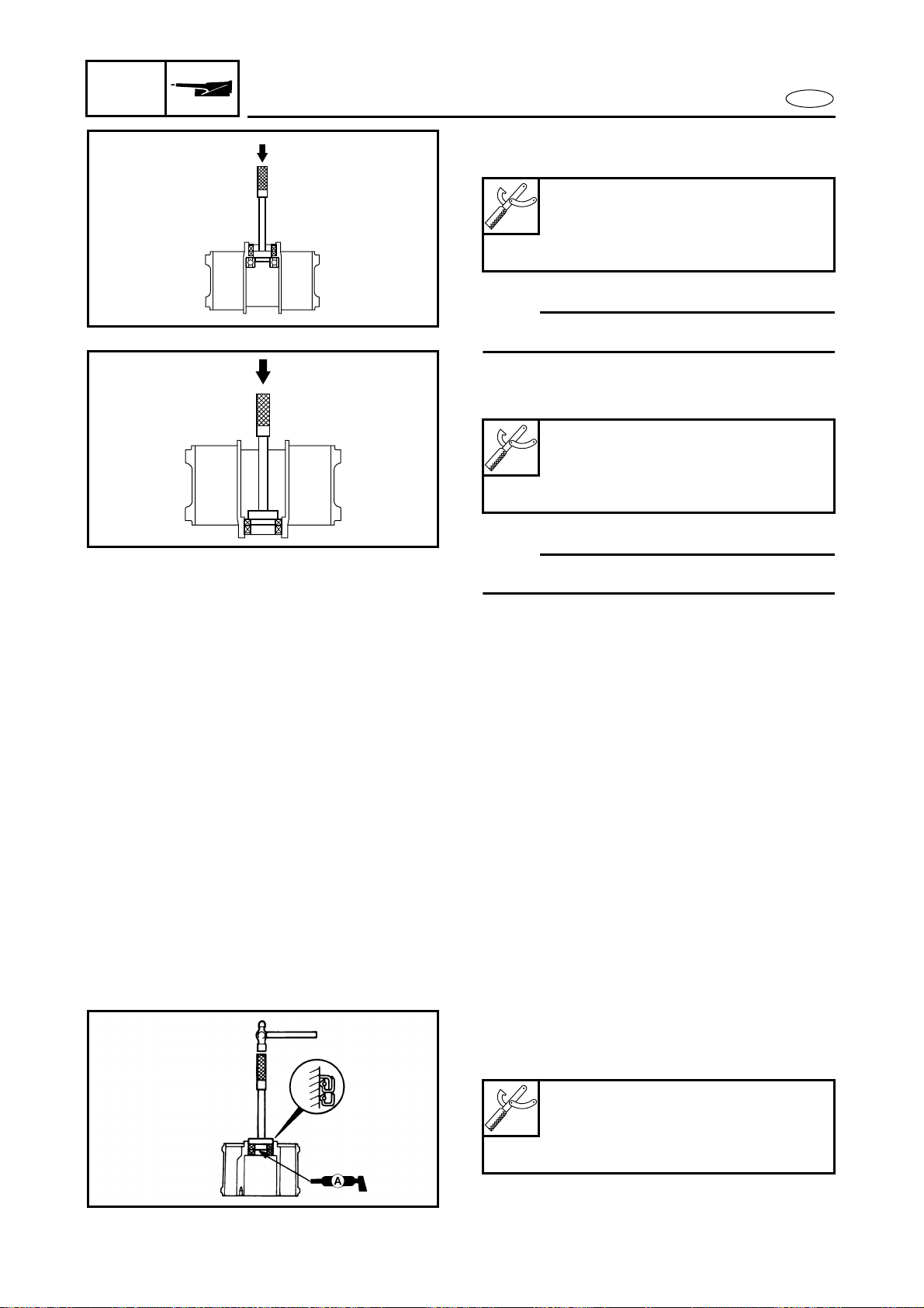
6-10
E
JET
PUMP
IMPELLER DUCT AND DRIVE SHAFT
5. Remove:
● Front bearing
NOTE:
Remove the front bearing with a press.
6. Remove:
● Oil seals
NOTE:
Remove the oil seals with press.
Impeller inspection
Refer to “JET PUMP UNIT” in
chapter 3.
Drive shaft inspection
1. Inspect:
● Drive shaft
Damage/wear → Replace.
Driver rod L3:
YB-06071/90890-06652
Needle bearing attachment:
YB-06112/90890-06614
Driver rod L3:
YB-06071/90890-06652
Needle bearing attachment:
YB-06196/90890-06653
Drive shaft installation
1. Install:
● Oil seals
Driver rod:
YB-06071/90890-06606
Ball bearing attachment:
YB-06156/90890-06634
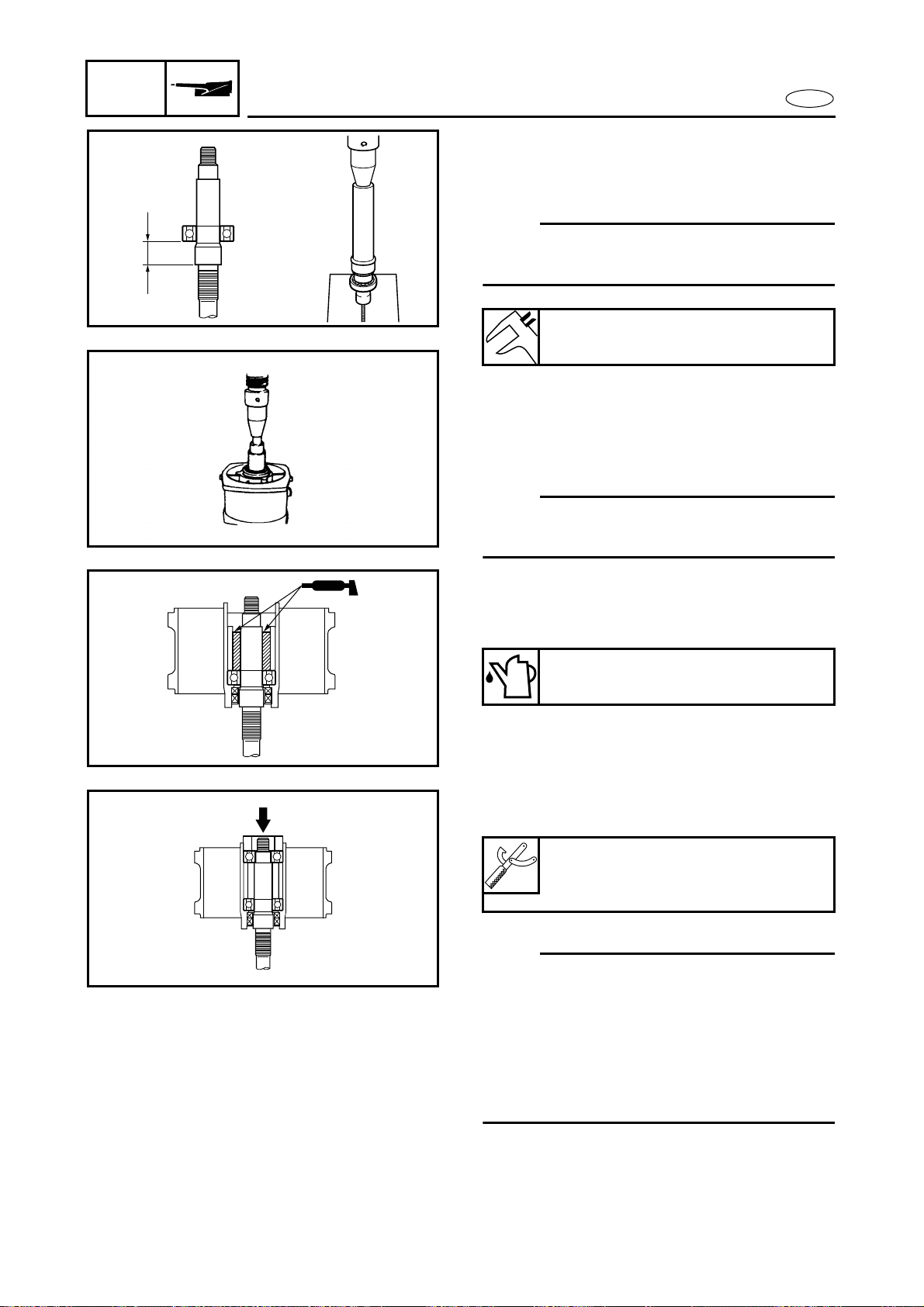
6-11
E
JET
PUMP
IMPELLER DUCT AND DRIVE SHAFT
2. Install:
● Front bearing
● Drive shaft
NOTE:
Install the front bearing and drive shaft with
a press.
3. Install:
● Drive shaft (with front bearing)
● Spacer
● Impeller duct
NOTE:
Press the spacer and the front bearing with
a 36-mm deep socket.
4. Add:
● EPNOC grease AP #0
(between the drive shaft and spacer)
Distance a:
23 ± 0.1 mm (0.91 ± 0.004 in)
Quantity:
Approximately 1/3 of capacity
a
5. Install:
● Rear bearing
NOTE:
● Press the bearing inner/outer race at the
same time holding the drive shaft and
impeller duct.
● If a bearing inner/outer race attachment is
not available, use a washer or pipe with
an outer diameter of 46 mm (1.81 in) and
an inner diameter of 20 mm (0.79 in).
Bearing inner/outer race
attachment:
YB-34474
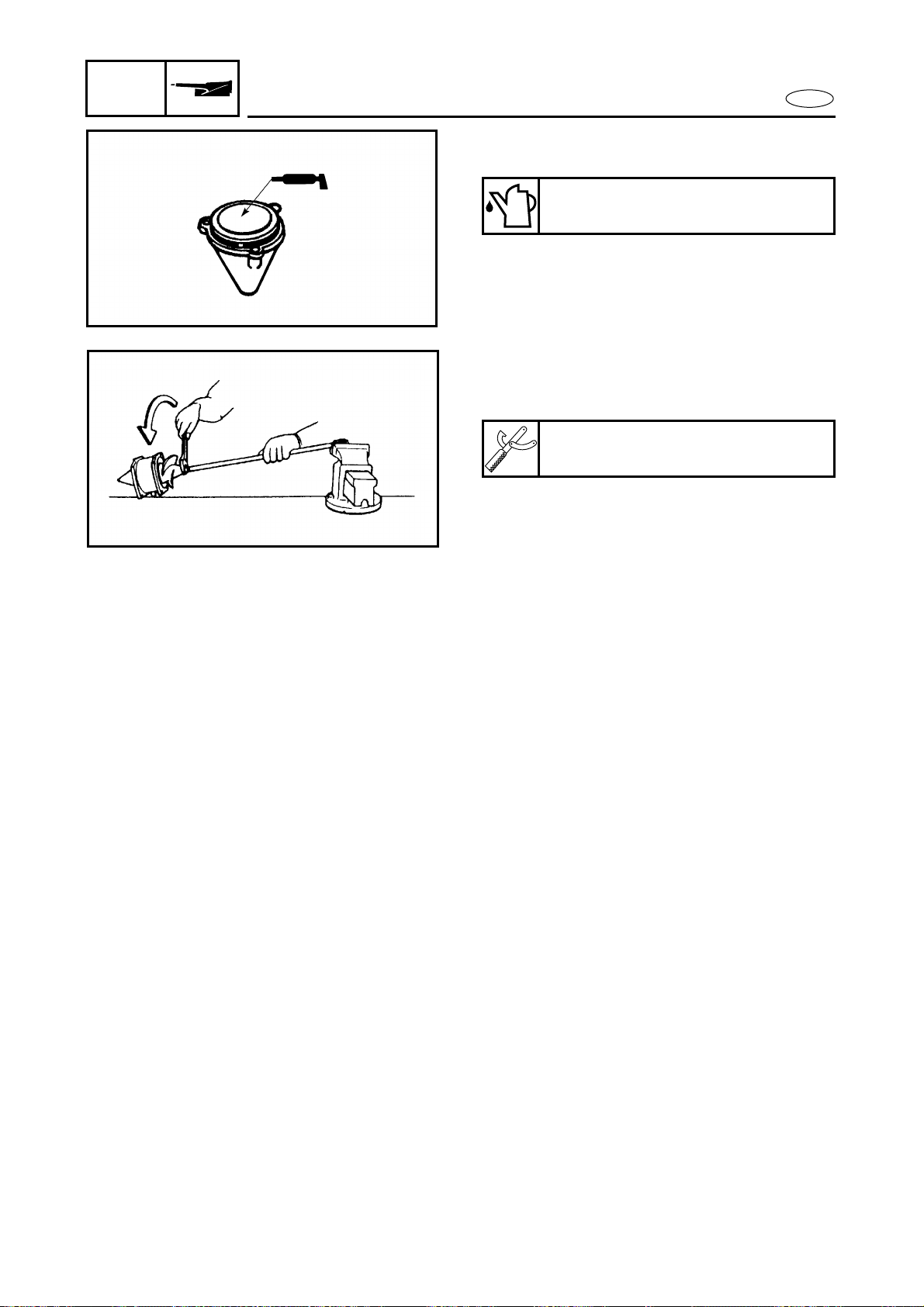
6-12
E
JET
PUMP
IMPELLER DUCT AND DRIVE SHAFT
6. Add:
● EPNOC grease AP #0 (into the cap)
Quantity:
Approximately 1/3 of capacity
7. Install:
● Nut
● Impeller
Drive shaft holder:
YB-06151/90890-06519
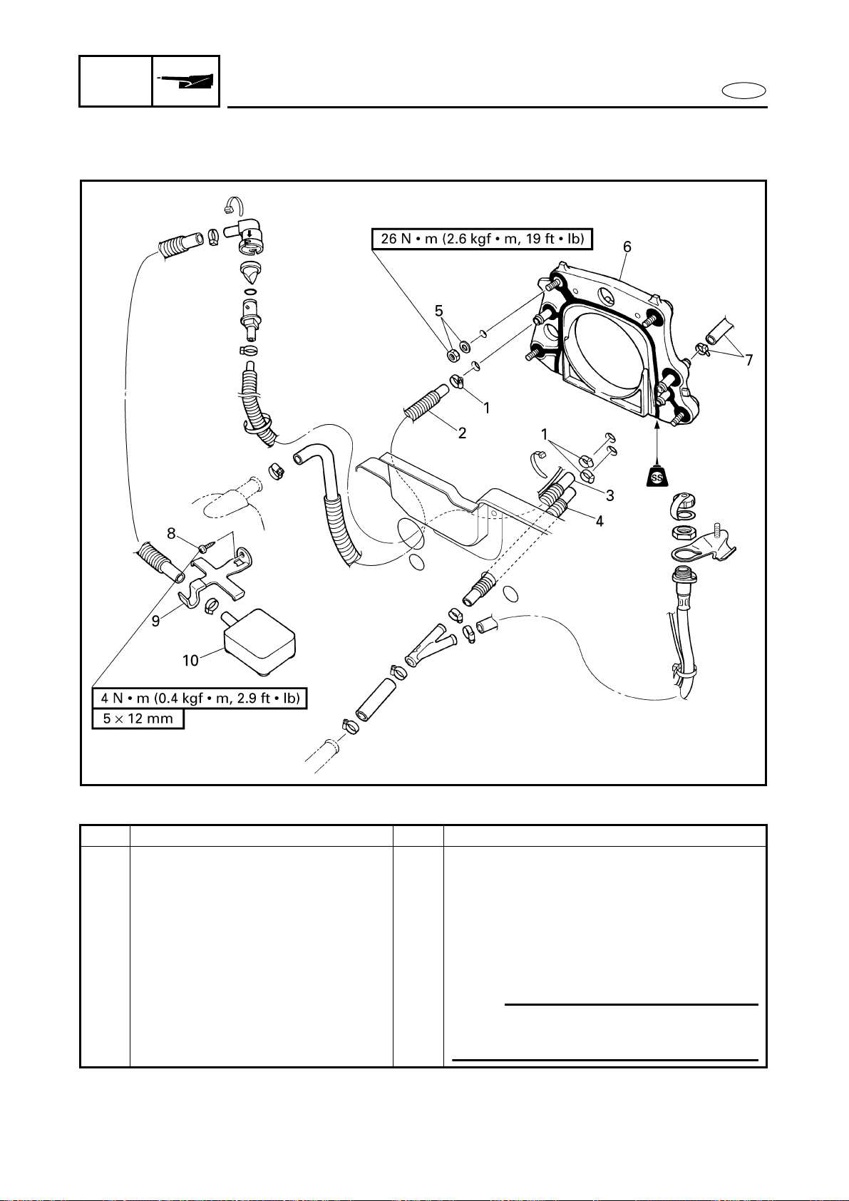
6-13
E
JET
PUMP
TRANSOM PLATE AND HOSES
TRANSOM PLATE AND HOSES
EXPLODED DIAGRAM
REMOVAL AND INSTALLATION CHART
Step Procedure/Part name Q’ty Service points
TRANSOM PLATE AND HOSES
REMOVAL
Follow the left “Step” for removal.
Exhaust system Refer to “EXHAUST SYSTEM” in
chapter 8.
Jet pump unit Refer to “JET PUMP UNIT”.
1 Hose clamp 3
2 Cooling water hose 1 Cooling water outlet
3 Bilge hose 1 1
NOTE:
Route the bilge hose 1 under the drive
shaft tube.
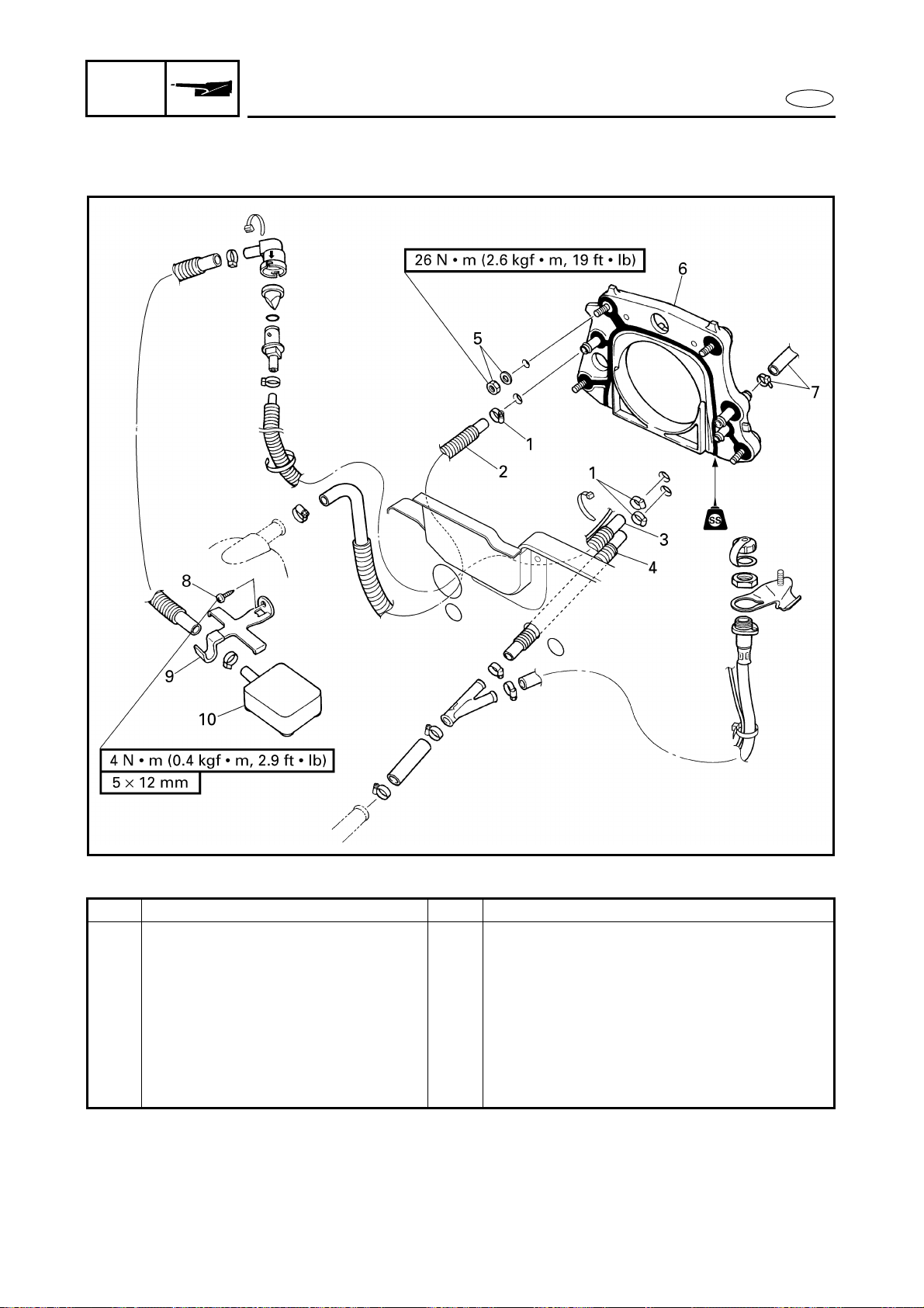
6-14
E
JET
PUMP
TRANSOM PLATE AND HOSES
EXPLODED DIAGRAM
Step Procedure/Part name Q’ty Service points
4 Cooling water hose 1 Cooling water inlet
5 Nut/washer 4/4
6 Transom plate 1
7 Clamp/bilge hose 2 1/1
8 Screw 1
9 Bilge strainer holder 1
10 Bilge strainer 1
Reverse the removal steps for installation.

6-15
E
JET
PUMP
TRANSOM PLATE AND HOSES
SERVICE POINTS
Bilge strainer inspection
Refer to “JET PUMP UNIT” in
chapter 3.
Bilge hose inspection
1. Inspect:
● Bilge hoses
Cracks/damage/wear → Replace.
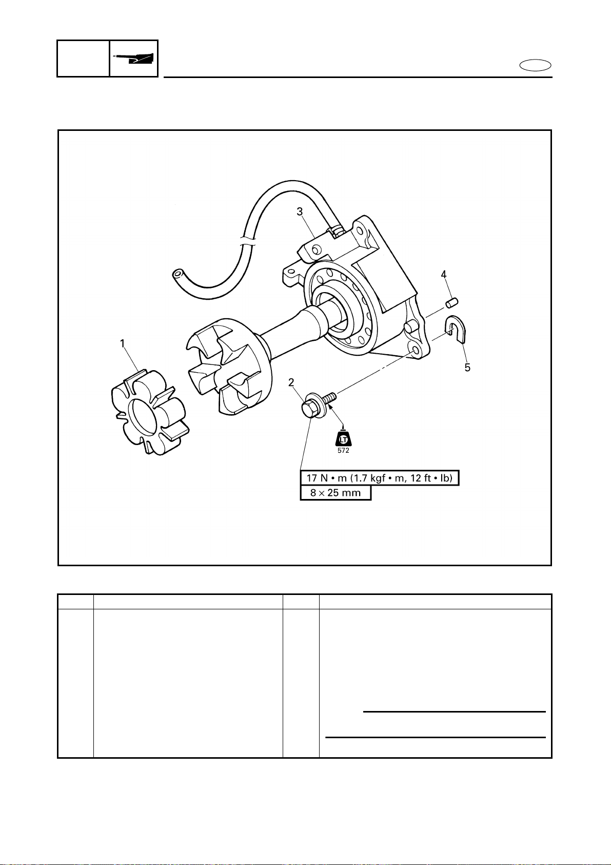
6-16
E
JET
PUMP
BEARING HOUSING
BEARING HOUSING
EXPLODED DIAGRAM
REMOVAL AND INSTALLATION CHART
Step Procedure/Part name Q’ty Service points
BEARING HOUSING REMOVAL Follow the left “Step” for removal.
Engine unit Refer to “ENGINE UNIT” in chapter 5.
1 Rubber coupling 1
2 Bolt 3
3 Intermediate housing assembly 1
4 Pin 2
5 Shim *
NOTE:
Install the shims in their original locations.
Reverse the removal steps for installation.
*: As required
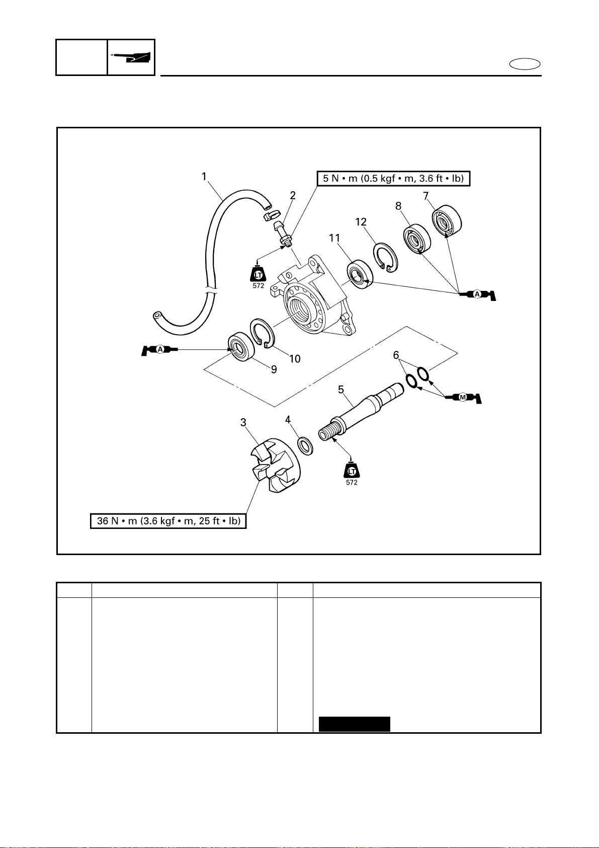
6-17
E
JET
PUMP
BEARING HOUSING
EXPLODED DIAGRAM
REMOVAL AND INSTALLATION CHART
Step Procedure/Part name Q’ty Service points
BEARING HOUSING
DISASSEMBLY
Follow the left “Step” for disassembly.
1 Grease hose 1
2 Nipple 1
3 Driven coupling 1
4 Washer 1
5 Intermediate drive shaft 1
6 O-ring 2
7 Oil seal 1
Not reusable
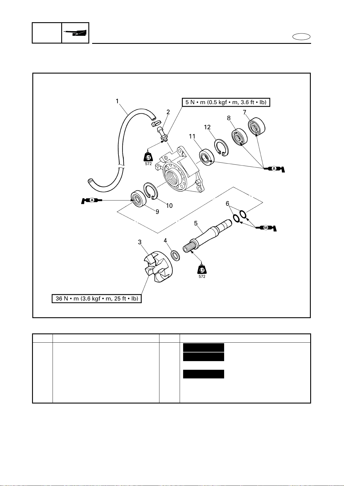
6-18
E
JET
PUMP
BEARING HOUSING
EXPLODED DIAGRAM
Step Procedure/Part name Q’ty Service points
8 Oil seal 1
9 Oil seal 1
10 Circlip 1
11 Bearing 1
12 Circlip 1
Reverse the disassembly steps for
assembly.
Not reusable
Not reusable
Not reusable
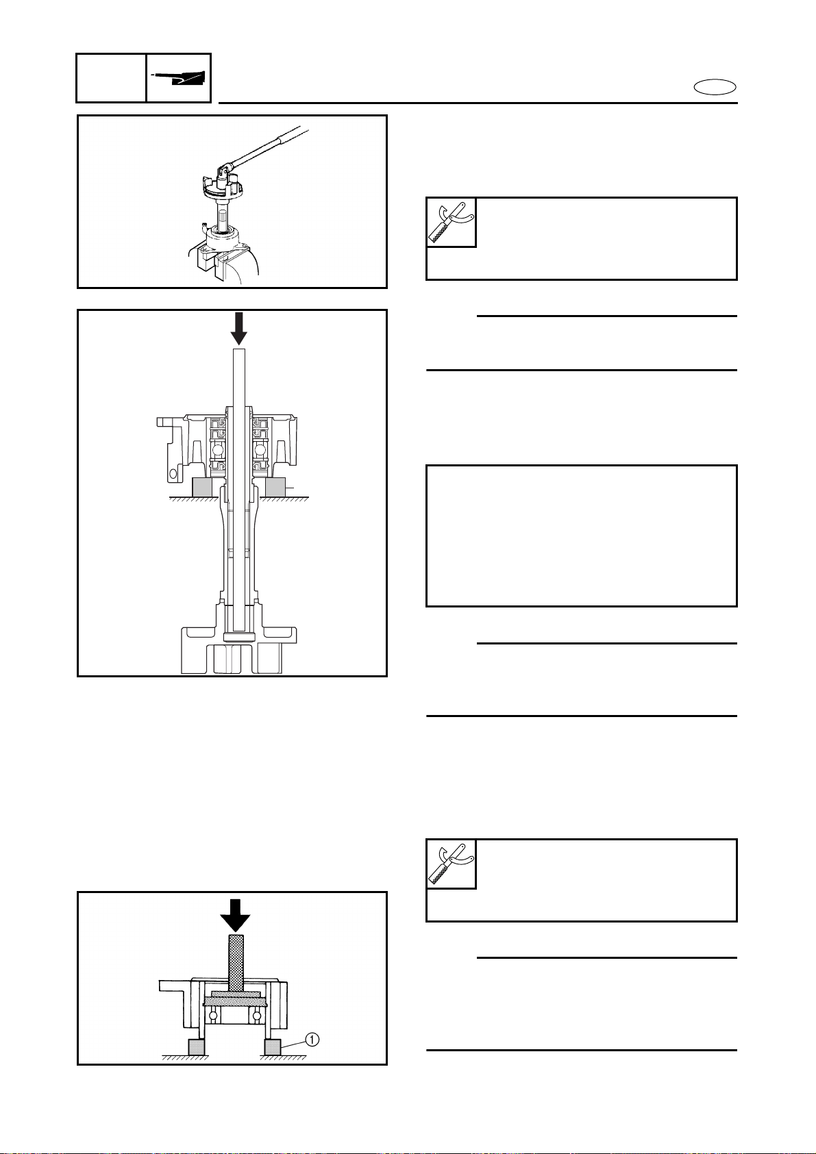
6-19
E
JET
PUMP
BEARING HOUSING
SERVICE POINTS
Driven coupling removal and installation
1. Remove and install:
● Driven coupling
NOTE:
Install the driven coupling with the same
special tools that were used for removal.
Intermediate drive shaft removal
1. Remove:
● Intermediate drive shaft
NOTE:
Support the intermediate housing with
steel blocks 1 and press the driven cou-
pling shaft.
Bearing removal
1. Remove:
● Bearing
NOTE:
● Install the bearing with the same special
tools that were used for removal.
● Support the intermediate housing with
steel blocks 1 and press the bearing.
Coupler wrench:
YW-06551/90890-06551
Shaft holder:
YB-06552/90890-06552
Removal steps:
● Temporarily install the driven coupling
to the intermediate drive shaft.
● Insert the long rod to the driven cou-
pling shaft.
● Press out the intermediate drive shaft
by pushing the rod.
Driver rod:
YB-06071/90890-06606
Bearing outer race attachment:
YB-06016/90890-06626
1
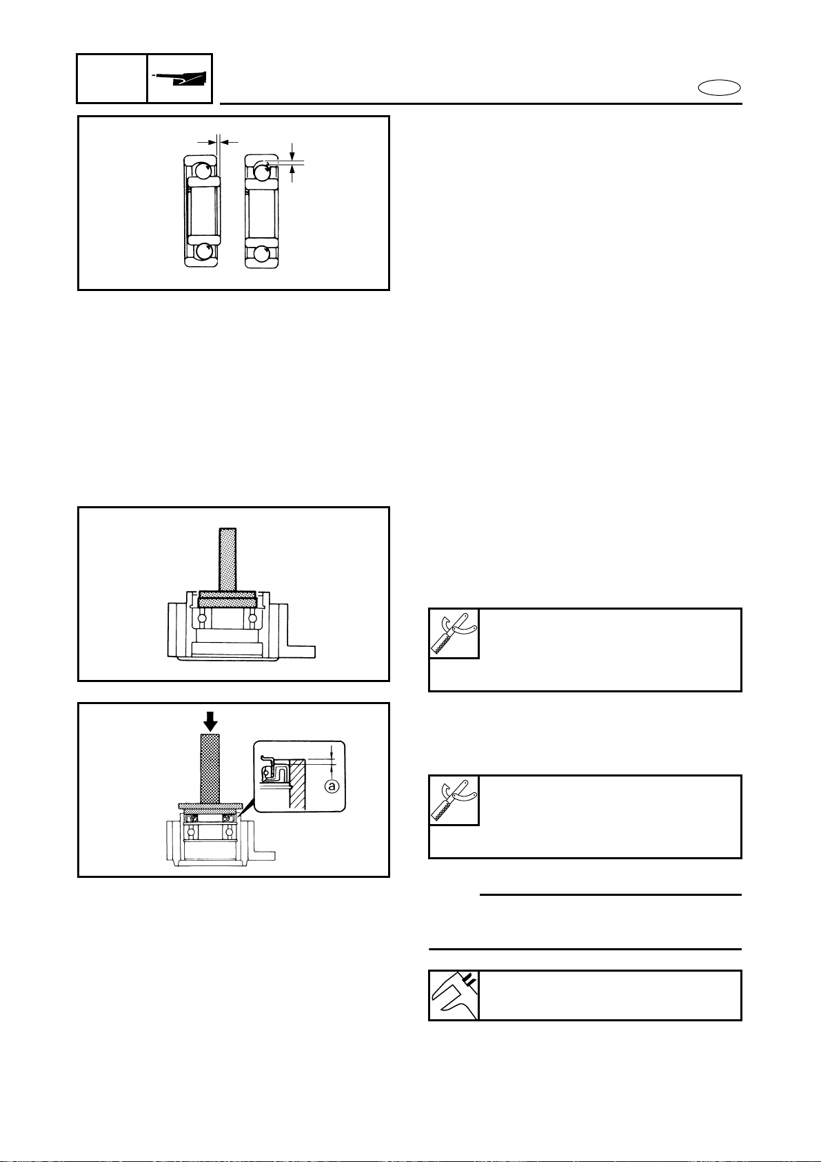
6-20
E
JET
PUMP
BEARING HOUSING
Bearing, driven coupling shaft, and grease
hose inspection
1. Inspect:
● Bearing
Rotate the inner race by hand.
Damage/rough movement → Replace.
● Intermediate drive shaft
Damage/pitting → Replace.
● Grease hose
Cracks/wear → Replace.
Driven coupling inspection
1. Inspect:
● Driven coupling
● Driven coupling damper
Damage/wear → Replace.
Bearing installation
1. Install:
● Circlip (rear)
2. Install:
● Bearing
Oil seal installation
1. Install:
● Oil seal
NOTE:
Before installing the oil seal, lubricate the
clip glove with water resistant grease.
Driver rod:
YB-06071/90890-06606
Bearing outer race attachment:
YB-06016/90890-06626
Driver rod:
YB-06071/90890-06606
Bearing outer race attachment:
YB-06016/90890-06626
Distance a:
6.8–7.2 mm (0.27–0.28 in)
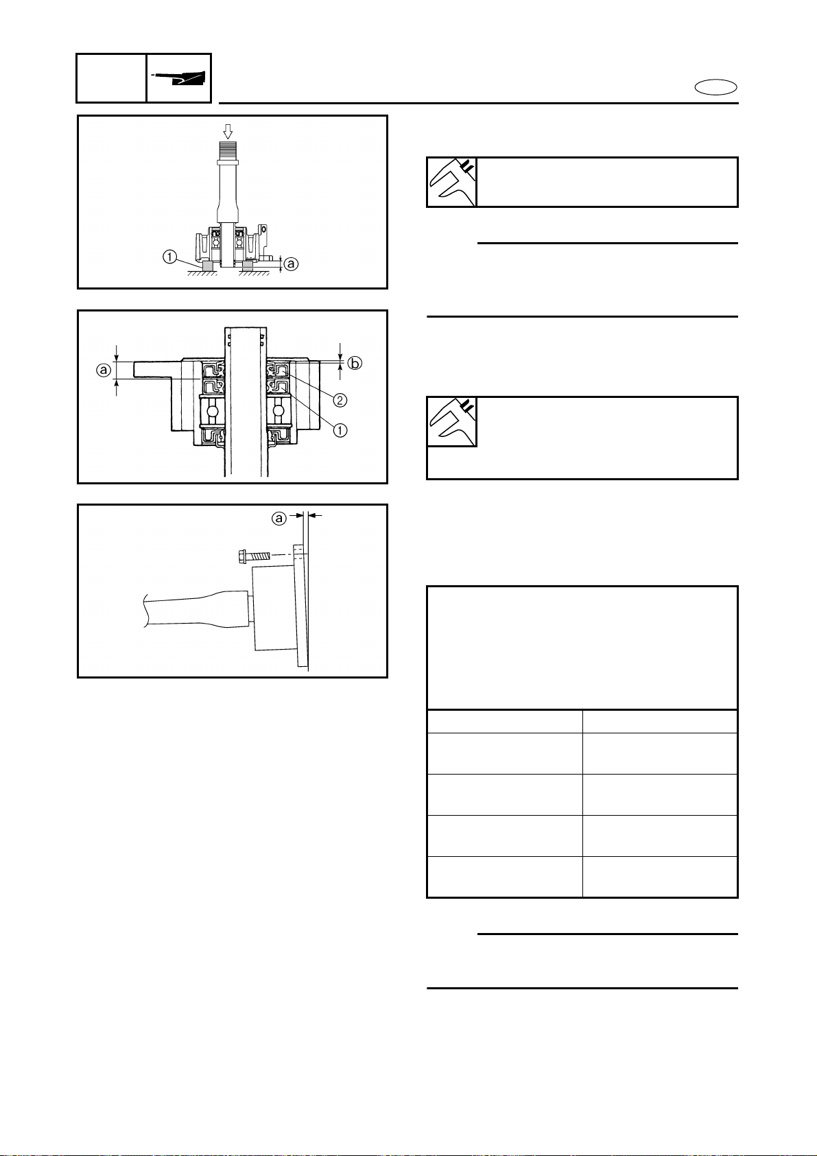
6-21
E
JET
PUMP
BEARING HOUSING
2. Install:
● Intermediate drive shaft
NOTE:
Support the intermediate housing with
steel blocks 1 and press the driven cou-
pling shaft.
3. Install:
● Oil seal 1 [8 mm (0.31 in)]
● Oil seal 2 [10 mm (0.39 in)]
Distance a:
9.5–10.5 mm (0.37–0.41 in)
Distance a:
10.3–10.7 mm (0.41–0.42 in)
Distance b:
1.6–2.0 mm (0.06–0.08 in)
Intermediate housing installation
1. Install:
● Intermediate housing
● Shim
NOTE:
Install the shim(s) to the original position if
the intermediate housing is not replaced.
Installation steps:
● Install the intermediate housing.
● Measure the clearance a at each bolt
hole.
● Install the suitable shim from the table
below.
Clearance a Shim thickness
0–0.2 mm
(0–0.008 in)
No need
0.3–0.7 mm
(0.012–0.028 in)
0.5 mm
0.8–1.2 mm
(0.031–0.047 in)
1.0 mm
1.3–2.0 mm
(0.051–0.079 in)
1.5 mm


E
–+
ELEC
CHAPTER 7
ELECTRICAL SYSTEM
ELECTRICAL COMPONENTS......................................................................... 7-1
ELECTRICAL BOX........................................................................................... 7-2
EXPLODED DIAGRAM............................................................................. 7-2
REMOVAL AND INSTALLATION CHART ............................................... 7-2
ELECTRICAL ANALYSIS ................................................................................ 7-6
INSPECTION............................................................................................. 7-6
Digital tester ...................................................................................... 7-6
Low resistance measurement .......................................................... 7-6
Peak voltage measurement.............................................................. 7-7
Peak voltage adaptor ........................................................................ 7-7
Test harness ..................................................................................... 7-8
IGNITION SYSTEM......................................................................................... 7-9
WIRING DIAGRAM................................................................................... 7-9
IGNITION SPARK GAP........................................................................... 7-10
IGNITION SYSTEM PEAK VOLTAGE.................................................... 7-11
SPARK PLUGS ....................................................................................... 7-12
SPARK PLUG CAPS ............................................................................... 7-12
IGNITION COIL....................................................................................... 7-12
ENGINE STOP SWITCH......................................................................... 7-13
THERMOSWITCH................................................................................... 7-13
STARTING SYSTEM..................................................................................... 7-14
WIRING DIAGRAM................................................................................. 7-14
BATTERY ................................................................................................ 7-15
WIRING CONNECTIONS ....................................................................... 7-15
FUSE ....................................................................................................... 7-15
STARTER SWITCH................................................................................. 7-15
STARTER RELAY.................................................................................... 7-16
STARTER MOTOR........................................................................................ 7-17
EXPLODED DIAGRAM........................................................................... 7-17
REMOVAL AND INSTALLATION CHART ............................................ 7-17
SERVICE POINTS ................................................................................... 7-20
Armature inspection ....................................................................... 7-20
Brush holder inspection ................................................................. 7-21
Starter motor front cover inspection............................................. 7-21

E
1
2
3
4
5
6
7
8
9
–+
ELEC
CHARGING SYSTEM.................................................................................... 7-22
WIRING DIAGRAM................................................................................. 7-22
FUSE ....................................................................................................... 7-23
BATTERY ................................................................................................ 7-23
RECTIFIER/REGULATOR PEAK VOLTAGE ........................................... 7-23
LIGHTING COIL PEAK VOLTAGE.......................................................... 7-23
YPVS ............................................................................................................. 7-24
WIRING DIAGRAM................................................................................. 7-24
FUSE ....................................................................................................... 7-25
BATTERY ................................................................................................ 7-25
PICKUP COIL .......................................................................................... 7-25
CDI UNIT................................................................................................. 7-25
YPVS SERVOMOTOR .................................................................................. 7-26
EXPLODED DIAGRAM........................................................................... 7-26
REMOVAL AND INSTALLATION CHART ............................................. 7-26
SERVICE POINTS ................................................................................... 7-27
YPVS cable removal and installation ............................................ 7-27
YPVS cable inspection .................................................................... 7-27
YPVS servomotor inspection ......................................................... 7-27
YPVS cable adjustment .................................................................. 7-28
INDICATION SYSTEM.................................................................................. 7-29
WIRING DIAGRAM................................................................................. 7-29
FUSE ....................................................................................................... 7-30
BATTERY ................................................................................................ 7-30
LIGHTING COIL ...................................................................................... 7-30
RECTIFIER/REGULATOR........................................................................ 7-30
CDI UNIT................................................................................................. 7-30
THERMOSWITCH................................................................................... 7-30
BUZZER .................................................................................................. 7-30
OIL LEVEL SENSOR............................................................................... 7-30
FUEL LEVEL SENSOR............................................................................ 7-31
MULTIFUNCTION METER..................................................................... 7-31
Multifunction meter ........................................................................ 7-31
MULTIFUNCTION METER REMOVAL .................................................. 7-31
Display function .............................................................................. 7-32
Fuel level gauge .............................................................................. 7-33
Oil level gauge................................................................................. 7-34
Overheat warning indicator ........................................................... 7-35
Speed meter .................................................................................... 7-36
Speed sensor................................................................................... 7-36
7-1
E
–+
ELEC
ELECTRICAL COMPONENTS
ELECTRICAL COMPONENTS
1
2
3
4
5
6
C
B
A
=
8
9
7
1 Buzzer
2 Fuel level sensor
3 Multifunction meter
4 YPVS servomotor
5 Spark plugs
6 Electrical box
7 Speed sensor
8 Battery
9 Thermoswitch
0 Starter motor
A Stator coil and pickup coil
B Engine stop switch, engine stop lanyard
switch and starter switch
C Oil level sensor

7-2
E
–+
ELEC
ELECTRICAL BOX
ELECTRICAL BOX
EXPLODED DIAGRAM
REMOVAL AND INSTALLATION CHART
Step Procedure/Part name Q’ty Service points
ELECTRICAL BOX DISASSEMBLY Follow the left “Step” for disassembly.
Electrical box Refer to “BATTERY BOX” in chapter 8.
1 Plastic locking tie 2
2 Bolt/collar 1/1
NOTE:
To separate the battery box from the
engine unit, refer to “ENGINE UNIT”,
“STARTER MOTOR” and “FLYWHEEL
MAGNETO” in Chapter 5 to disconnect
the leads.
3 Plastic clamp 1
4 Bolt 14
5 Electrical box cover 1
6 Gasket 1
Not reusable
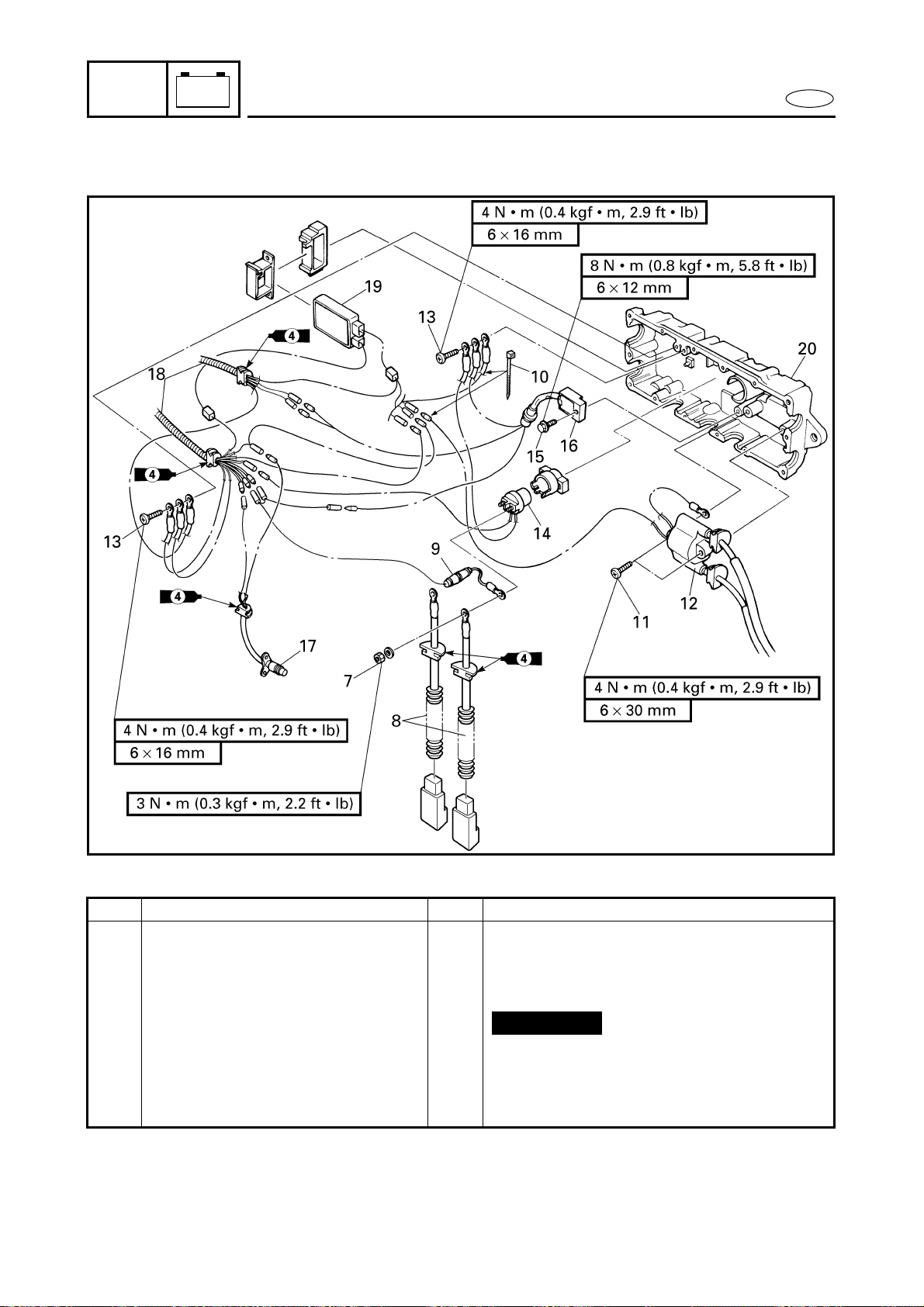
7-3
E
–+
ELEC
ELECTRICAL BOX
EXPLODED DIAGRAM
Step Procedure/Part name Q’ty Service points
7 Nut 2
8 Starter motor lead/
battery positive lead
1/1
9 Fuse 1
10 Plastic locking tie 1
11 Screw 2
12 Ignition coil 1
13 Screw 2
14 Starter relay 1
Not reusable
7-4
E
–+
ELEC
ELECTRICAL BOX
EXPLODED DIAGRAM
Step Procedure/Part name Q’ty Service points
15 Bolt 1
16 Rectifier/regulator 1
17 Thermoswitch 1
18 Wire harness 2
19 CDI unit 1
20 Electrical box housing 1
Reverse the disassembly steps for
assembly.
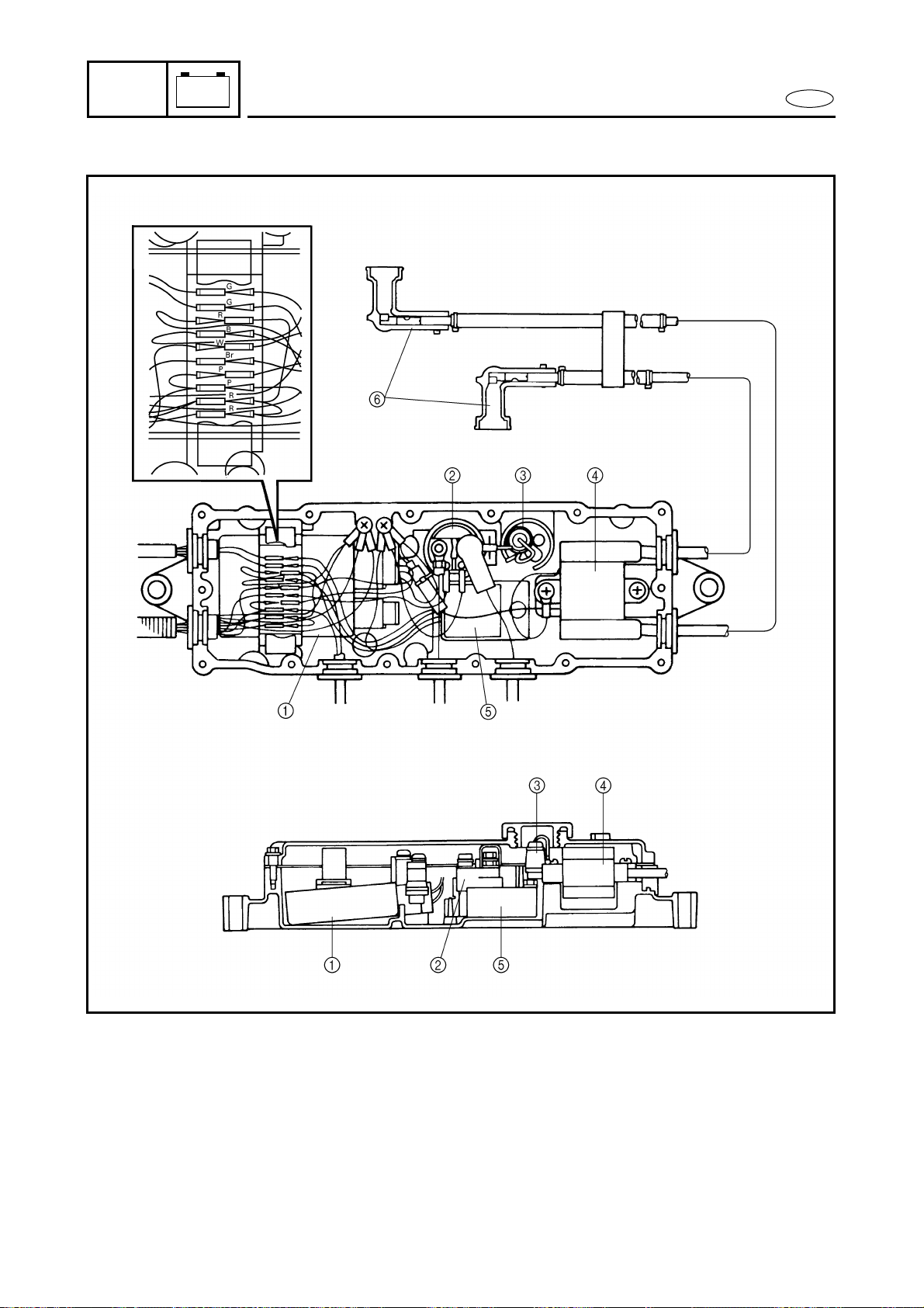
7-5
E
–+
ELEC
ELECTRICAL BOX
1 CDI unit
2 Starter relay
3 Fuse (10A)
4 Ignition coil
5 Rectifier/regulator
6 Spark plug caps
B : Black
Br : Brown
G : Green
P : Pink
R : Red
W : White
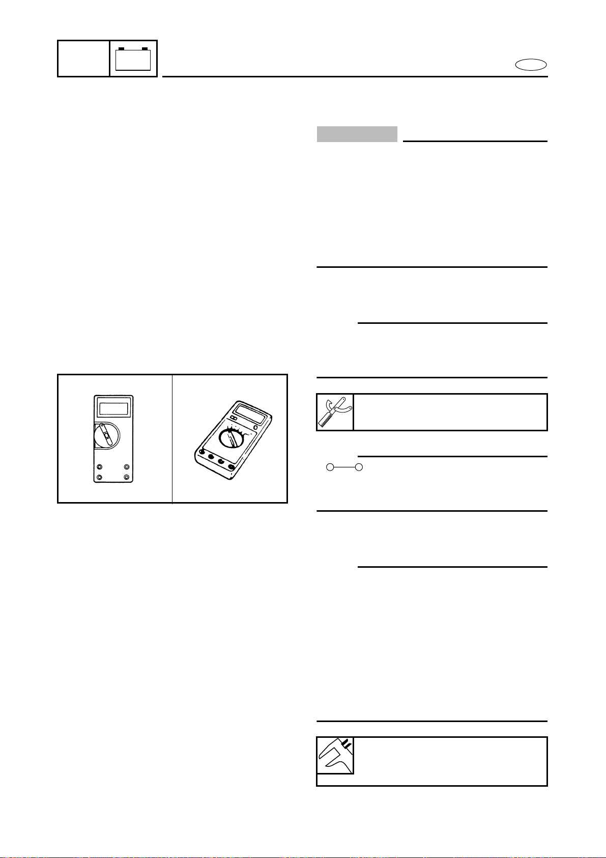
7-6
E
–+
ELEC
ELECTRICAL ANALYSIS
ELECTRICAL ANALYSIS
INSPECTION
CAUTION:
● All measuring instruments should be han-
dled with special care. Damaged or mis-
handled instruments will not measure
properly.
● On an instrument powered by dry batter-
ies, check the battery’s voltage periodi-
cally and replace the batteries if
necessary.
Digital tester
NOTE:
Throughout this chapter the digital tester’s
part number has been omitted. Refer to the
following part number.
NOTE:
“ ” indicates a continuity of electric-
ity; i.e., a closed circuit at the respective
switch position.
Low resistance measurement
NOTE:
● When measuring a resistance of 10 Ω or
less with the digital tester, the correct
measurement cannot be obtained
because of the tester’s internal resistance.
● To obtain the correct value, subtract the
internal resistance from the displayed
measurement.
● The internal resistance of the tester can be
obtained by connecting both of its termi-
nals.
Digital tester:
J-39299/90890-06752
Correct value =
Displayed measurement –
Internal resistance
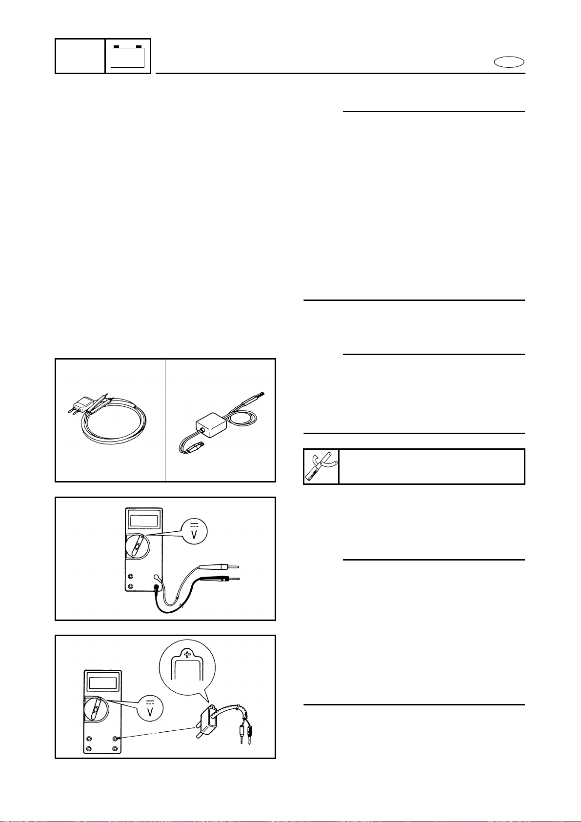
7-7
E
–+
ELEC
ELECTRICAL ANALYSIS
Peak voltage measurement
NOTE:
● When checking the condition of the igni-
tion system it is vital to know the peak
voltage.
● Cranking speed is dependant on many
factors (e.g., fouled or weak spark plugs, a
weak battery). If one of these is defected,
the peak voltage will be lower than speci-
fication.
● If the peak voltage measurement is not
within specification the engine will not
operate properly.
● A low peak voltage will also cause compo-
nents to prematurely wear.
Peak voltage adaptor
NOTE:
● Throughout this chapter the peak voltage
adaptor’s part number has been omitted.
Refer to the following part number.
● The peak voltage adaptor should be used
with the digital tester.
● When measuring the peak voltage, con-
nect the peak voltage adaptor to the digi-
tal tester and switch the selector to the
DC voltage mode.
NOTE:
● Make sure that the adaptor leads are
properly installed in the digital tester.
● Make sure that the positive pin (the “+”
mark facing up as shown) on the adaptor
is installed into the positive terminal of
the tester.
● The test harness is needed for the follow-
ing tests.
Å Voltage measurement
ı Peak voltage measurement
Peak voltage adaptor:
YU-39991/90890-03169
Å
ı
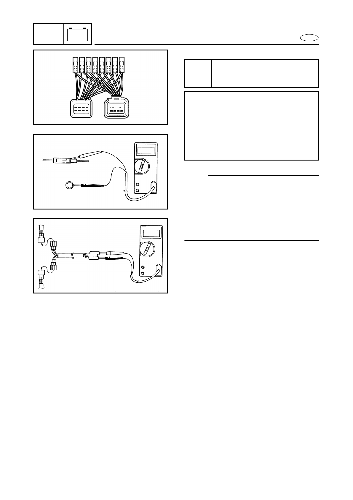
7-8
E
–+
ELEC
ELECTRICAL ANALYSIS
Test harness
NOTE:
● Make sure the output lead (red lead) of the
rectifier/regulator is disconnected when
measuring the peak voltage of the lighting
coil and rectifier/regulator.
● If the charge coil and pickup coil are mea-
sured unloaded, disconnect the test har-
ness on the output side coupler.
YW- 90890- Pin Usage
06779 06779 8 Charge coil and
pickup coil
Checking steps:
● Disconnect the coupler connections.
● Connect the test harness between the
couplers.
● Connect the tester terminals to the ter-
minals which are being checked.
● Run the engine and observe the mea-
surement.
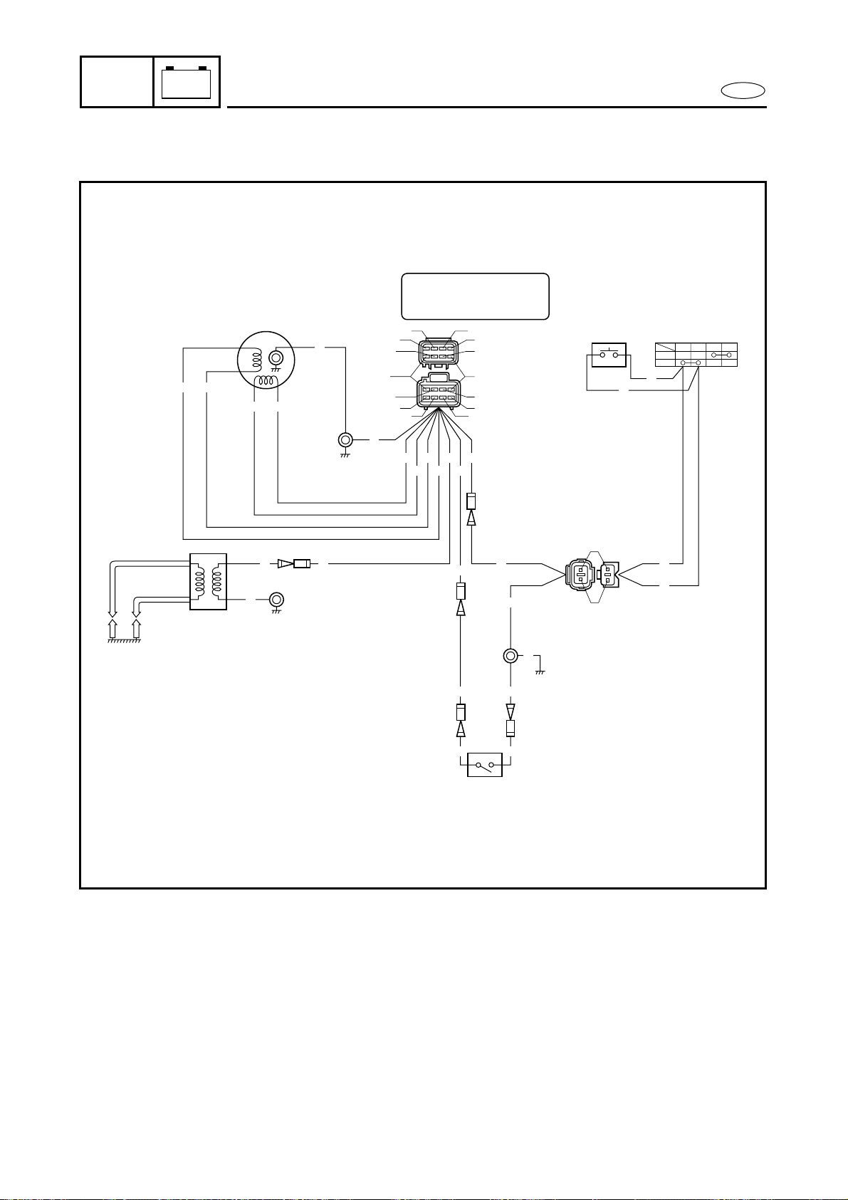
7-9
E
–+
ELEC
IGNITION SYSTEM
IGNITION SYSTEM
WIRING DIAGRAM
P
W/B
W/R
W
O
P
O
Br
Br
L
L
B
B
W/B
SET
PULL
1
2
6
8
7
45
B
B
O O
P
P B
P
W
B
B
W
B
W
B
Br L
W/B W/R
3
B
B
L
Br
W/R
W/B
O W
P
WBRBr
W
B
1 Pickup coil
2 Charge coil
3 CDI unit
4 Engine stop switch
5 Engine stop lanyard switch
6 Thermoswitch
7 Ignition coil
8 Spark plugs
B : Black
Br : Brown
L : Blue
O : Orange
P : Pink
R : Red
W : White
W/B : White/black
W/R : White/red
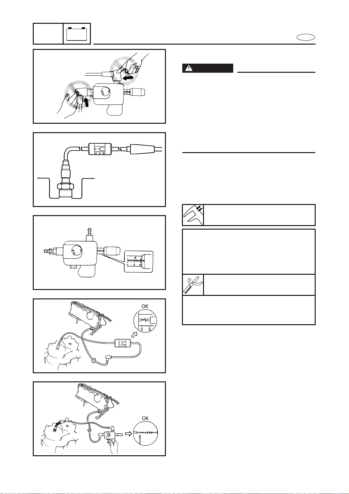
7-10
E
–+
ELEC
IGNITION SYSTEM
IGNITION SPARK GAP
WARNING
● When checking the spark gap, do not
touch any of the connections of the spark
gap tester lead wires.
● When performing the spark gap test, take
special care not to let sparks leak out of
the removed spark plug cap.
● When performing the spark gap check,
keep flammable gas or liquids away,
since this test can produce sparks.
1. Check:
● Ignition spark gap
Below specification → Check the CDI
unit output peak voltage.
Check the ignition coil for resistance.
Å For USA and Canada
ı For worldwide
Spark gap:
10 mm (0.39 in)
Checking steps:
● Connect the spark plug cap to the
spark gap tester.
● Set the spark gap length on the adjust-
ing knob.
Spark gap tester:
YM-34487/90890-06754
● Crank the engine and observe the igni-
tion system spark through the dis-
charge window.
Å
ı
Å
ı
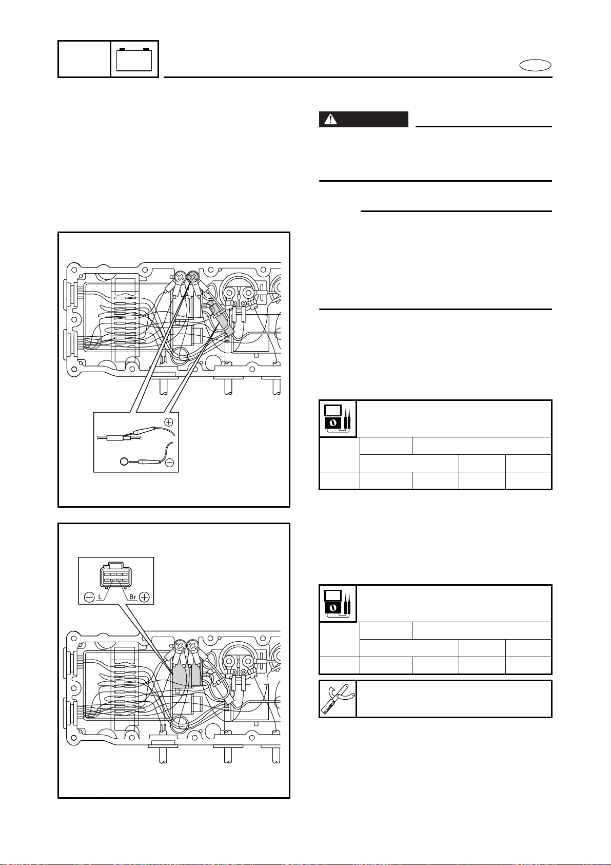
7-11
E
–+
ELEC
IGNITION SYSTEM
IGNITION SYSTEM PEAK VOLTAGE
WARNING
When checking the electrical components,
do not touch any of the connections of the
digital tester lead wires.
NOTE:
● If there is no spark or the spark is weak,
continue with the ignition system test.
● If a good spark is obtained, the problem is
not with the ignition system, but possibly
with the spark plug(s) or another compo-
nent.
1. Measure:
● CDI unit output peak voltage
Below specification → Measure the
charge coil output peak voltage or
replace the CDI unit.
CDI unit output peak voltage:
Orange (O) – Black (B)
r/min
Unloaded Loaded
Cranking 2,000 3,500
V 85 110 205 200
2. Measure:
● Charge coil output peak voltage
Below specification → Replace the
charge coil.
Charge coil output peak voltage:
Brown (Br) – Blue (L)
r/min
Unloaded Loaded
Cranking 2,000 3,500
V 90 120 220 210
Test harness (8-pin):
YW-06779/90890-06779
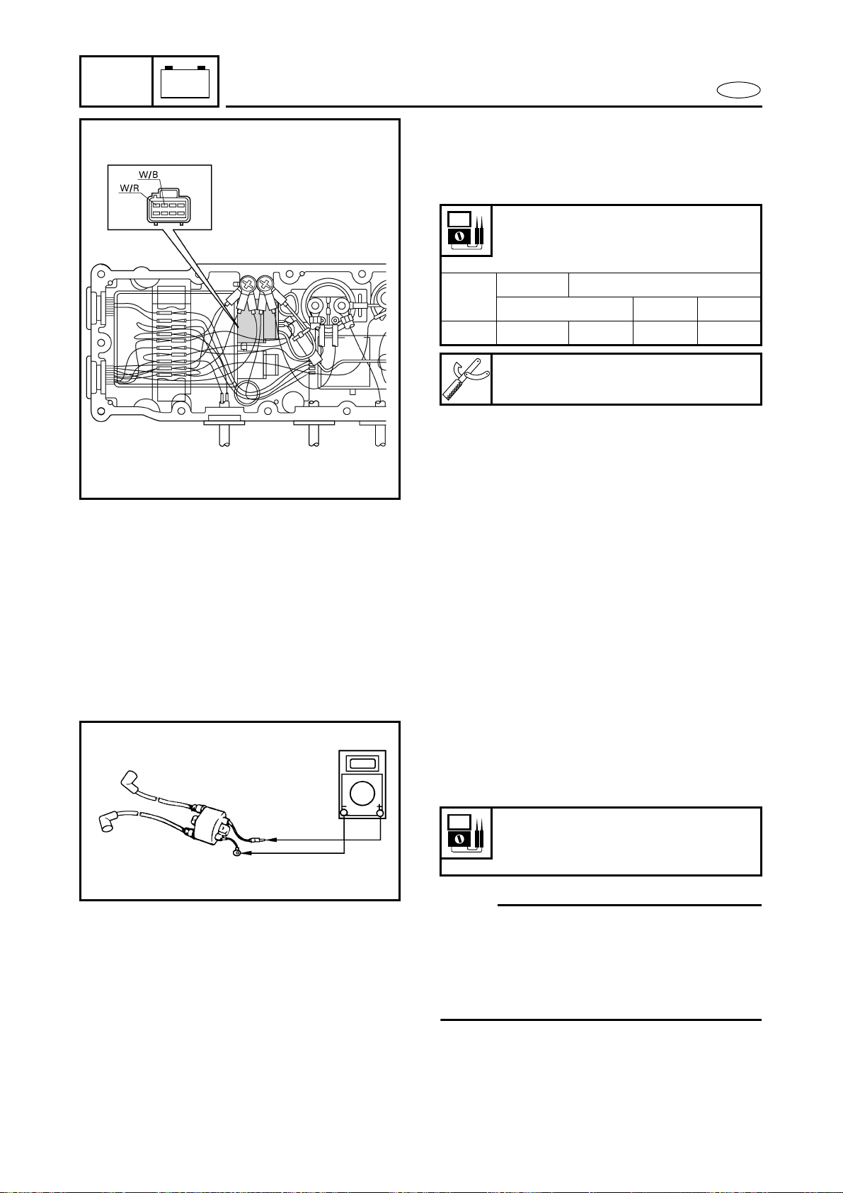
7-12
E
–+
ELEC
IGNITION SYSTEM
3. Measure:
● Pickup coil output peak voltage
Below specification → Replace the
pickup coil.
Pickup coil output peak voltage:
White/red (W/R) –
White/black (W/B)
r/min
Unloaded Loaded
Cranking 2,000 3,500
V5 3711
Test harness (8-pin):
YW-06779/90890-06779
SPARK PLUGS
Refer to “POWER UNIT” in chapter 3.
SPARK PLUG CAPS
1. Inspect:
● Spark plug cap
Loose → Tighten.
Cracks/damage → Replace.
IGNITION COIL
1. Measure:
● Primary coil resistance
Out of specification → Replace.
NOTE:
When measuring a resistance of 10 Ω or
less with the digital tester, the correct mea-
surement cannot be obtained because of
the tester’s internal resistance.
Refer to “Low resistance measurement”.
Primary coil resistance:
Orange (O) – Black (B)
0.078–0.106 Ω at 20 ˚C (68 ˚F)
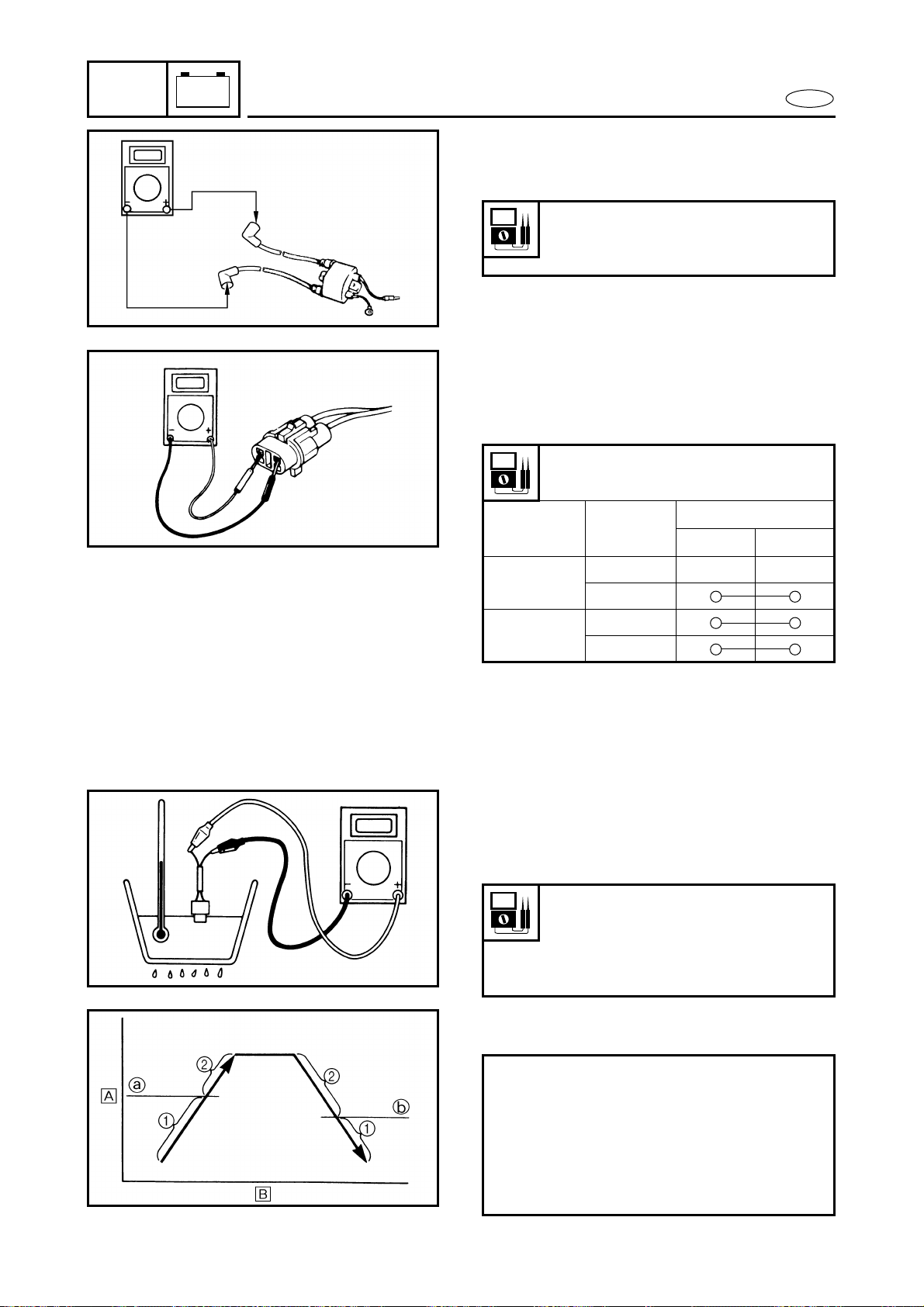
7-13
E
–+
ELEC
IGNITION SYSTEM
2. Measure:
● Secondary coil resistance
Out of specification → Replace.
Secondary coil resistance:
Spark plug cap – Spark plug cap
14.3–30.5 kΩ at 20 ˚C (68 ˚F)
ENGINE STOP SWITCH
1. Check:
● Engine stop switch continuity
Out of specification → Replace.
Engine stop switch continuity
(black coupler)
Lock plate Position
Lead color
White Black
Installed
Free
Push
Removed
Free
Push
THERMOSWITCH
1. Measure:
● Thermoswitch continuity
Out of specification → Replace.
1 No continuity Å Temperature
2 Continuity ı Time
Thermoswitch continuity
temperature:
Pink (P) – Black (B)
a 80 ˚C (177 ˚F)
b 70 ˚C (159 ˚F)
Measurement steps:
● Suspend the thermostat in a container
filled with water.
● Place a thermometer in the water.
● Slowly heat the water.
● Measure the continuity when the spec-
ified temperature is reached.
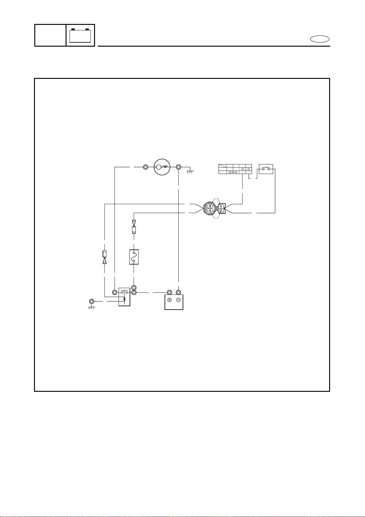
7-14
E
–+
ELEC
STARTING SYSTEM
STARTING SYSTEM
WIRING DIAGRAM
SET
PULL
23
R
Br
R
Br
Br
WBRBr
M
1
R
B
4
5
6
B
RBr
Br
R
R
B
R
R
Br
1 Starter motor
2 Engine stop lanyard switch
3 Starter switch
4 Fuse (10A)
5 Starter relay
6 Battery
B : Black
Br : Brown
R : Red
W : White
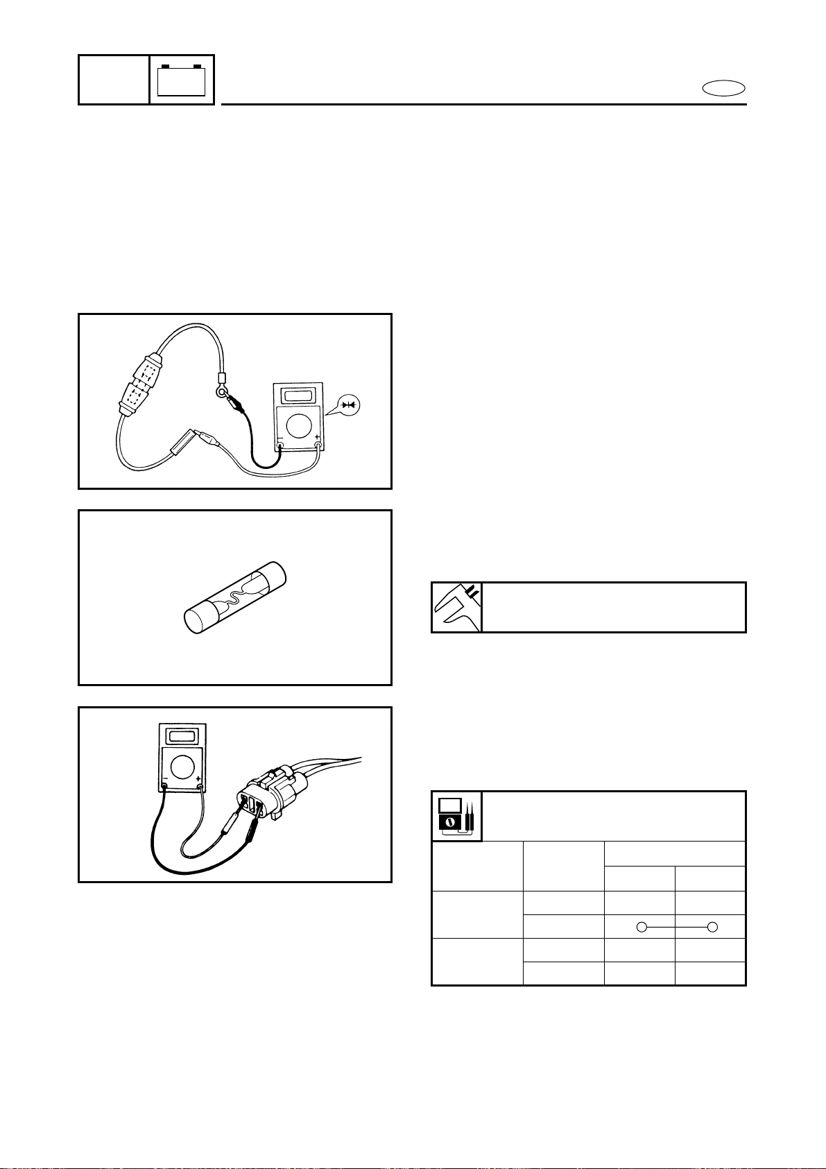
7-15
E
–+
ELEC
STARTING SYSTEM
BATTERY
Refer to “ELECTRICAL” in chapter 3.
WIRING CONNECTIONS
1. Check:
● Wiring connections
Poor connections → Properly connect.
FUSE
1. Check:
● Fuse holder continuity
No continuity → Check the fuse
holder leads.
2. Check:
● Fuse holder lead continuity
No continuity → Replace the fuse
holder.
Continuity → Check the fuse.
3. Check:
● Fuse broken
Broken → Replace.
Fuse rating:
10A
STARTER SWITCH
1. Check:
● Continuity
Out of specification → Replace.
Starter continuity
(natural coupler)
Lock plate Position
Leads
Red Brown
Installed
Free
Push
Removed
Free
Push
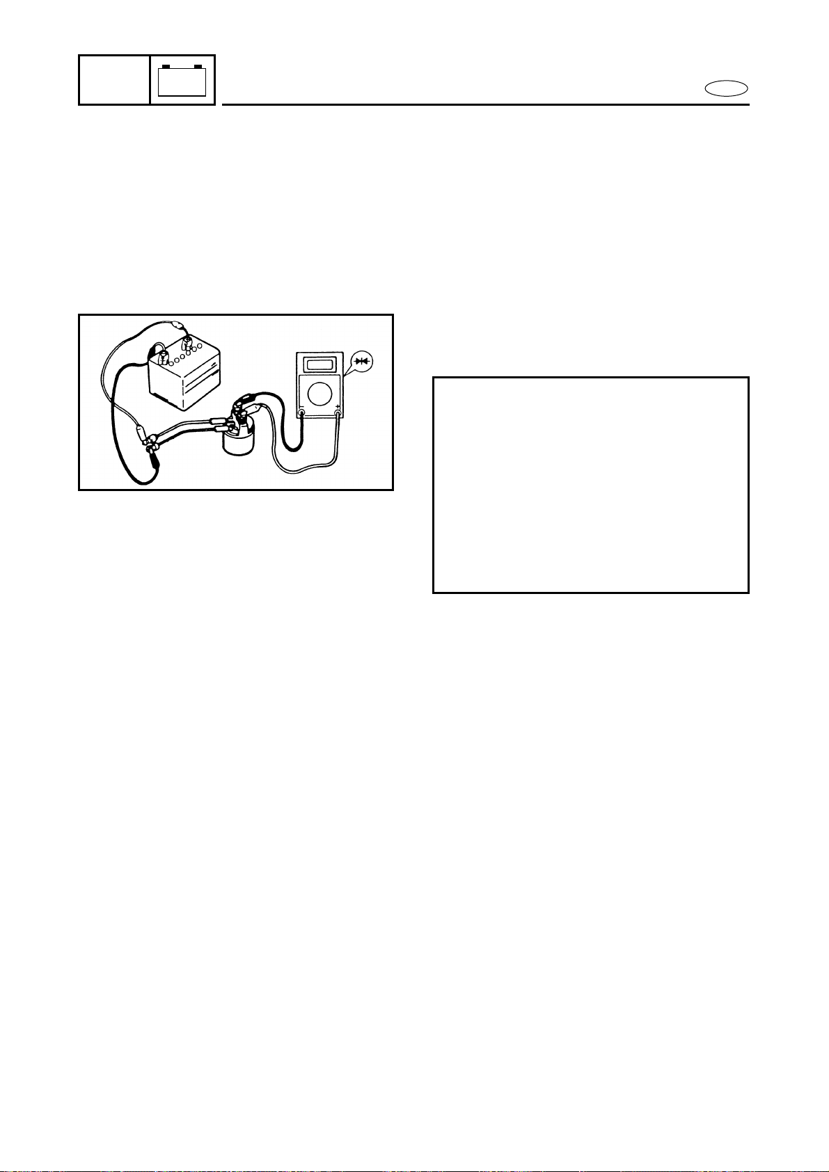
7-16
E
–+
ELEC
STARTING SYSTEM
STARTER RELAY
1. Inspect:
● Brown lead terminal
● Black lead terminal
Loose → Tighten.
2. Check:
● Starter relay
Faulty → Replace.
Checking steps:
● Connect the tester leads between the
starter relay terminals as shown.
● Connect the brown lead terminal to
the positive battery terminal.
● Connect the black lead terminal to the
negative battery terminal.
● Check that there is continuity between
the starter relay terminals.
● Check that there is no continuity after
the brown or black lead is removed.
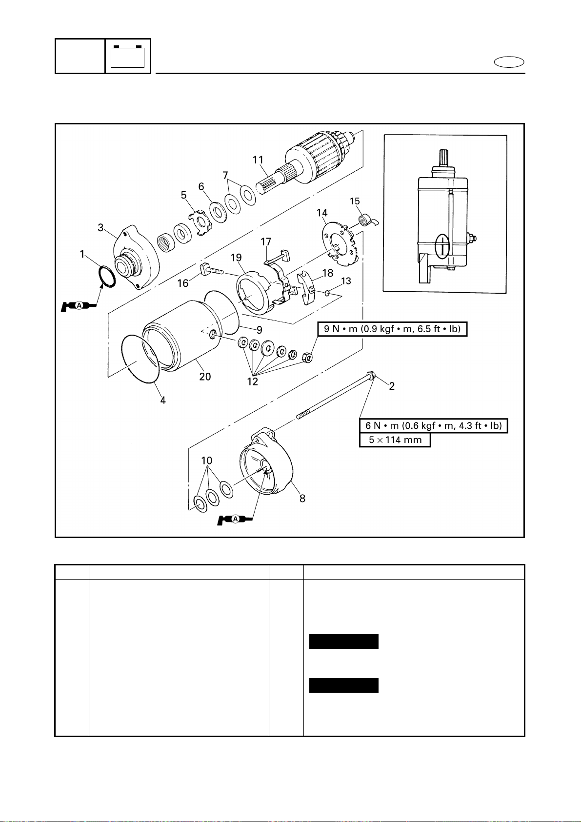
7-17
E
–+
ELEC
STARTER MOTOR
EXPLODED DIAGRAM
REMOVAL AND INSTALLATION CHART
Step Procedure/Part name Q’ty Service points
STARTER MOTOR
DISASSEMBLY
Follow the left “Step” for disassembly.
Starter motor Refer to “STARTER MOTOR”
in chapter 5.
1 O-ring 1
2 Bolt 2
3 Starter motor front cover 1
4 O-ring 1
5 Oil seal retainer 1
6 Washer 1
7 Shim * t = 0.2 mm, 0.5 mm
*: As required
Not reusable
Not reusable
STARTER MOTOR
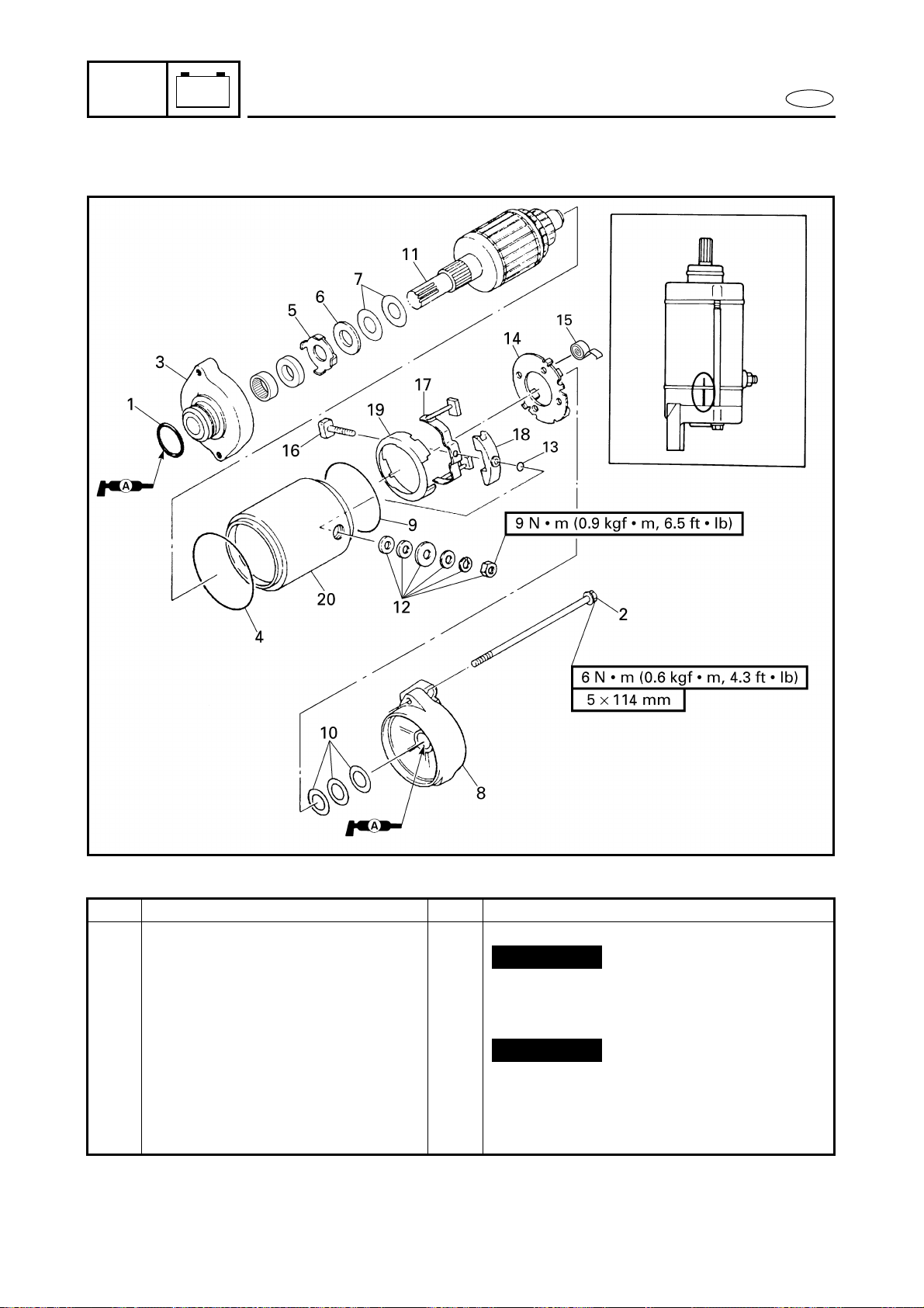
7-18
E
–+
ELEC
STARTER MOTOR
EXPLODED DIAGRAM
Step Procedure/Part name Q’ty Service points
8 Starter motor rear cover 1
9 O-ring 1
10 Shim * t = 0.2 mm, 0.8 mm
11 Armature assembly 1
12 Nut/spring washer/washer 1/1/4
13 O-ring 1
14 Brush holder 1
15 Brush spring 4
16 Bolt 1
17 Brush assembly 1
*: As required
Not reusable
Not reusable
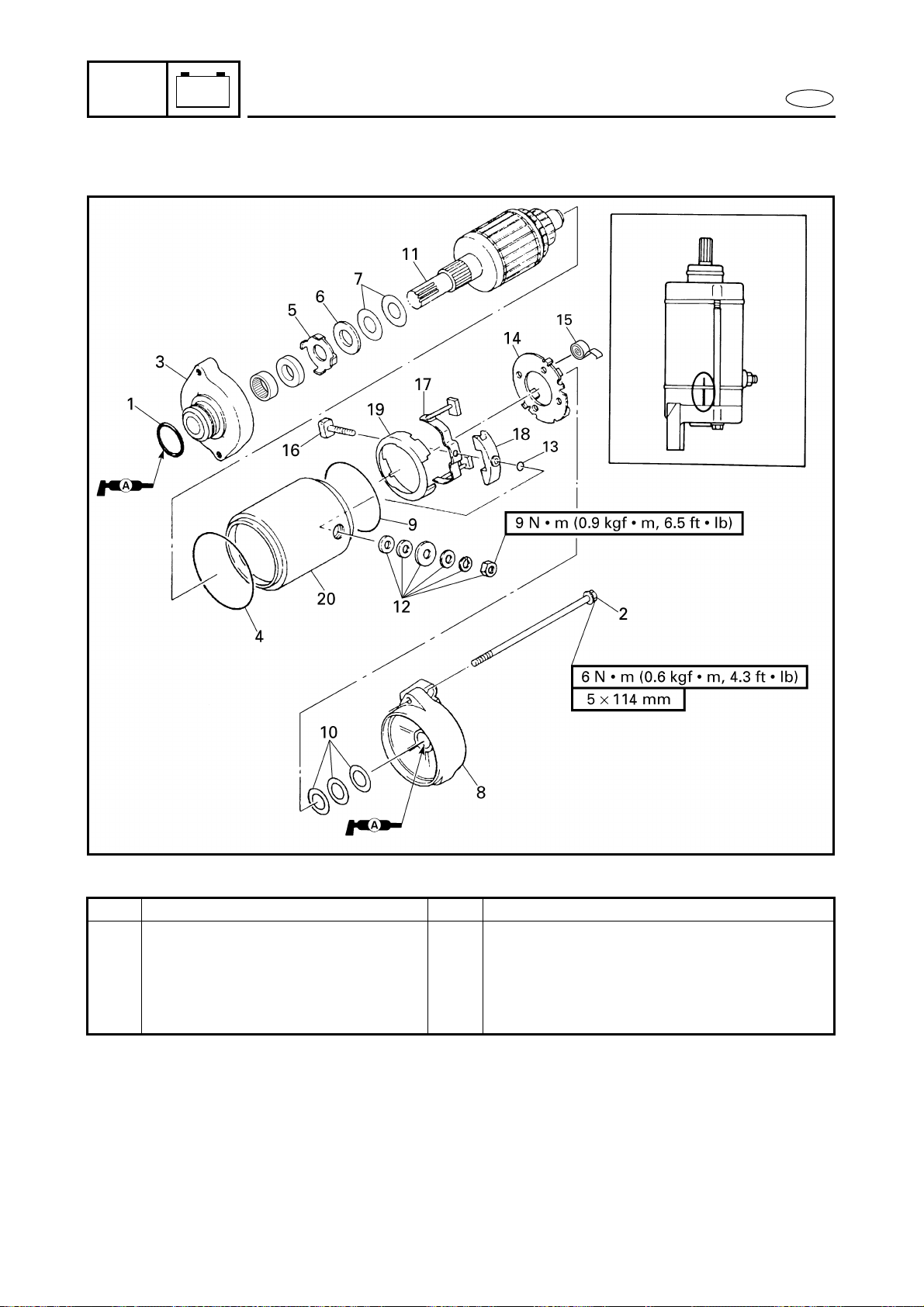
7-19
E
–+
ELEC
STARTER MOTOR
EXPLODED DIAGRAM
Step Procedure/Part name Q’ty Service points
18 Spacer 1
19 Holder 1
20 Starter motor yoke 1
Reverse the disassembly steps for
assembly.
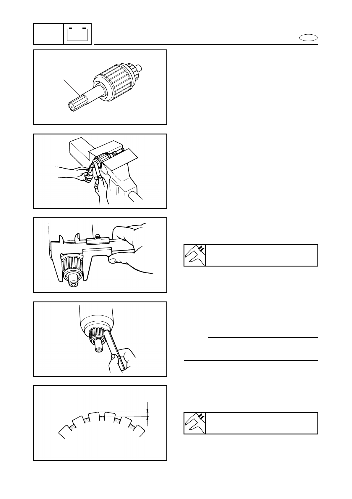
7-20
E
–+
ELEC
STARTER MOTOR
SERVICE POINTS
Armature inspection
1. Inspect:
● Armature shaft 1
Damage/wear → Replace.
1
2. Inspect:
● Commutator
Dirt → Clean with 600 grit sandpaper.
3. Measure:
● Commutator diameter
Out of specification → Replace.
Min. commutator diameter:
27.0 mm (1.06 in)
4. Check:
● Commutator undercut
Contaminants → Clean.
NOTE:
Remove all mica and metal particles with
compressed air.
5. Measure:
● Commutator undercut
Out of specification → Replace.
Min. commutator undercut:
0.2 mm (0.01 in)
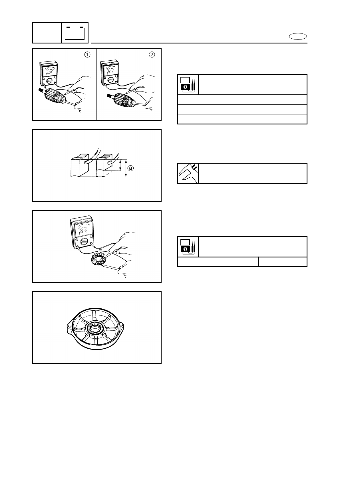
7-21
E
–+
ELEC
STARTER MOTOR
6. Inspect:
● Armature coil continuity
Out of specification → Replace.
Armature coil continuity:
Commutator segments 1 Continuity
Segment - Laminations 2 No continuity
Segment - Armature shaft No continuity
Brush holder inspection
1. Measure:
● Brush length a
Out of specification → Replace.
Min. brush length:
6.5 mm (0.26 in)
2. Check:
● Brush holder continuity
Out of specification → Replace.
Brush holder continuity:
Brush holder - Base No continuity
Starter motor front cover inspection
1. Inspect:
● Starter motor front cover bushing
Damage/wear → Replace the starter
motor front cover.
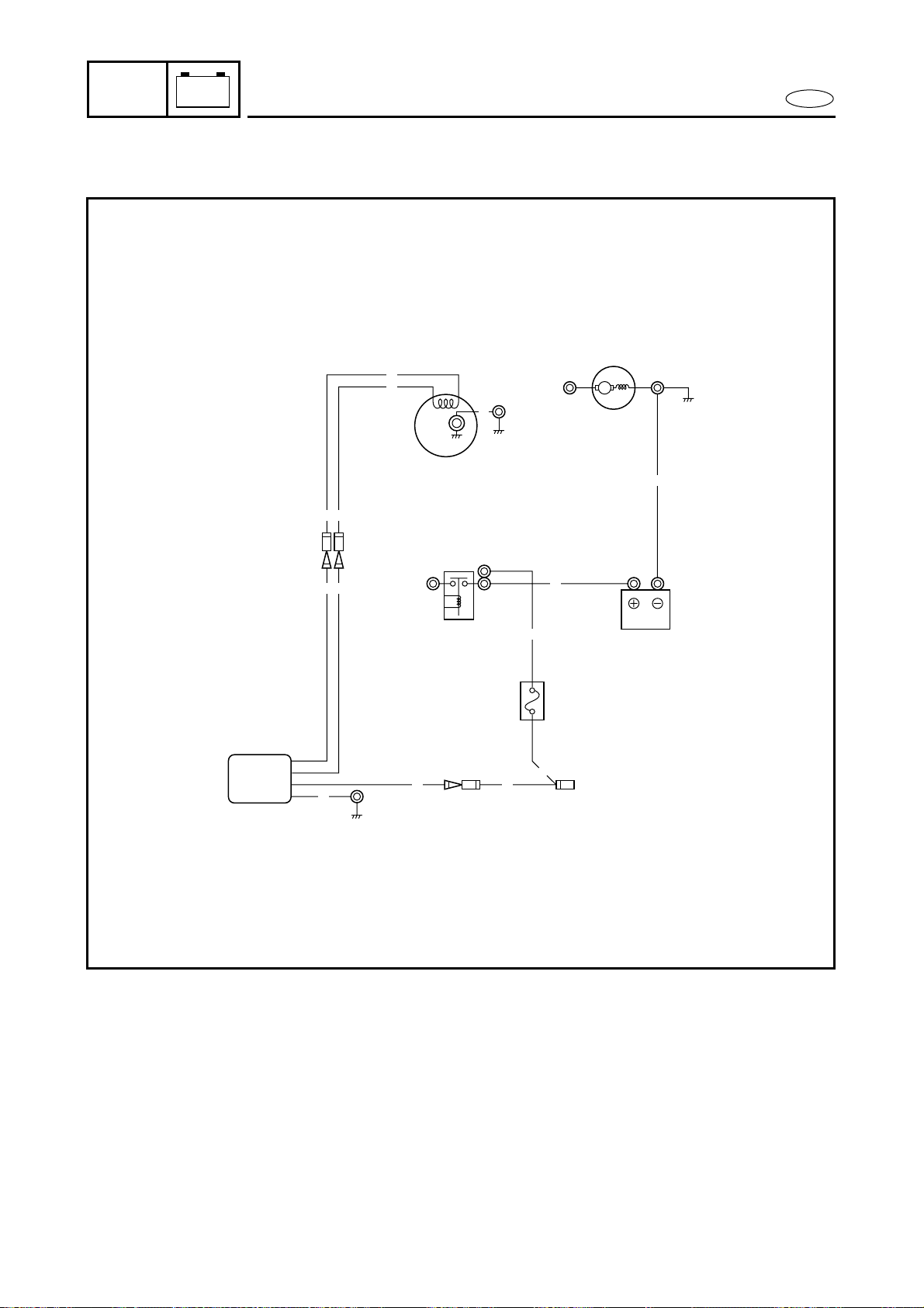
7-22
E
–+
ELEC
CHARGING SYSTEM
CHARGING SYSTEM
WIRING DIAGRAM
3
2
R
R
M
B
1
G
G
4
B
G
G
B
R R
R
G
G
1 Lighting coil
2 Battery
3 Fuse (10A)
4 Rectifier/regulator
B : Black
G : Green
R : Red
G/W : Green/white
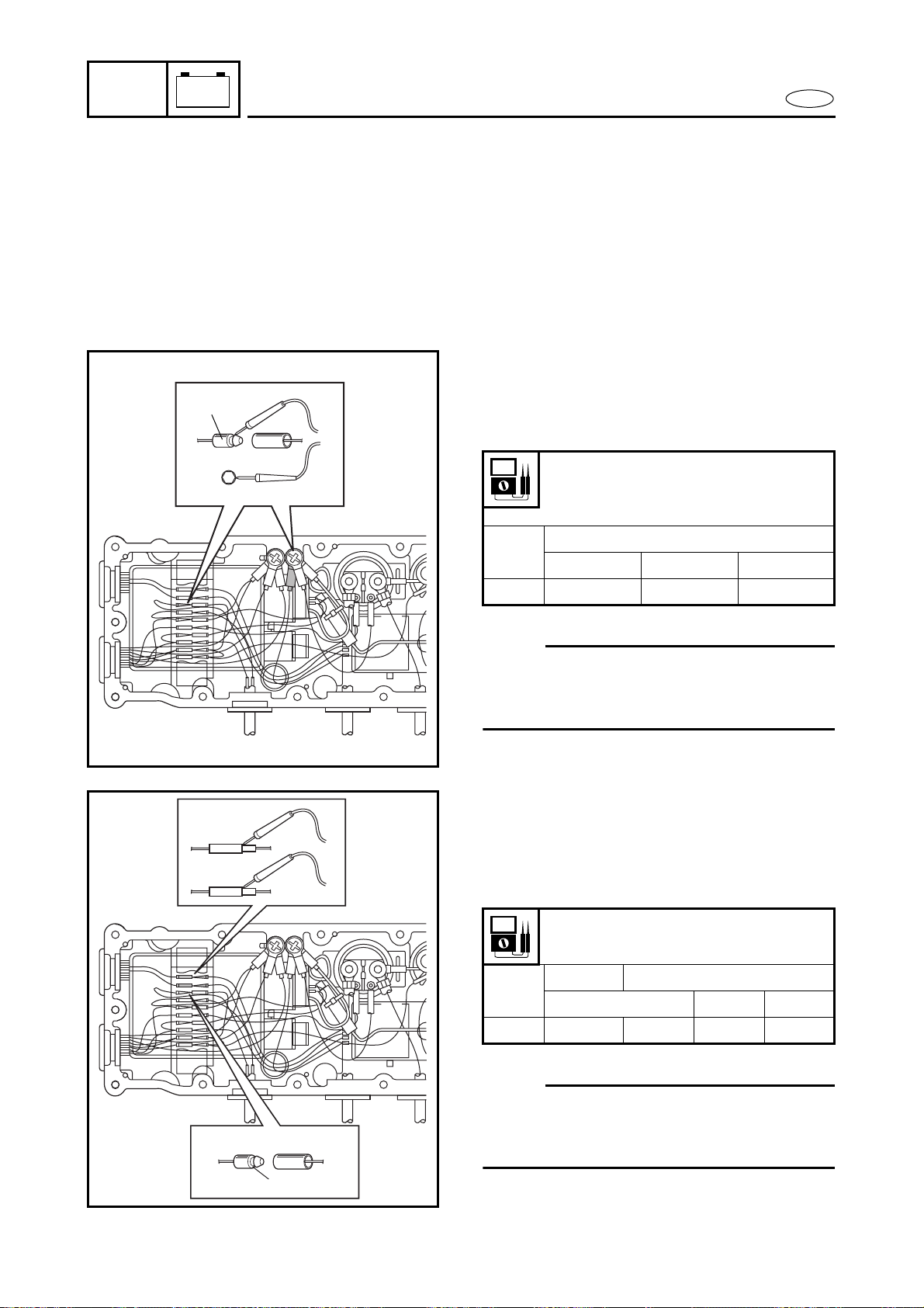
7-23
E
–+
ELEC
CHARGING SYSTEM
FUSE
Refer to “STARTING SYSTEM”.
BATTERY
Refer to “ELECTRICAL” in chapter 3.
RECTIFIER/REGULATOR PEAK
VOLTAGE
1. Measure:
● Rectifier/regulator output peak
voltage
Below specification → Measure the
lighting coil output peak voltage or
replace the rectifier/regulator.
NOTE:
Make sure the output lead (red lead) 1 of
the rectifier/regulator is disconnected when
measuring the output peak voltage.
Rectifier/regulator output peak
voltage:
Red (R) – Black (B)
r/min
Unloaded
Cranking 2,000 3,500
V 7.5 12.5 12.5
1
LIGHTING COIL PEAK VOLTAGE
1. Measure:
● Lighting coil output peak voltage
Below specification → Replace the
lighting coil.
NOTE:
Make sure the output lead (red lead) 1 of
the rectifier/regulator is disconnected when
measuring the output peak voltage.
Lighting coil output peak voltage:
Green (G) – Green (G)
r/min
Unloaded Loaded
Cranking 2,000 3,500
V 8.5 8.5 13 13
1
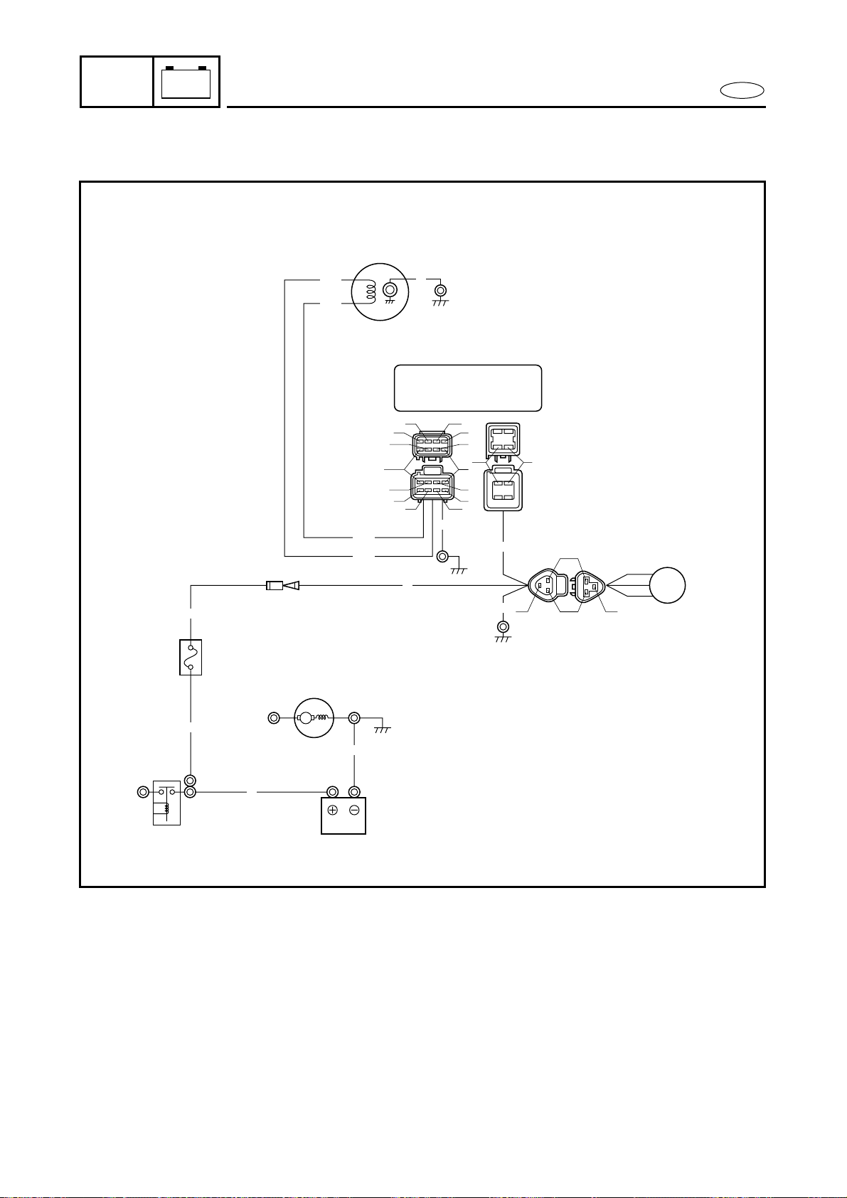
7-24
E
–+
ELEC
YPVS
WIRING DIAGRAM
1
W/B
W/R
W/R
W/B
3
R
B
B
Gy
B
M
5
4
R
R
R
B
2
Gy
B
R
Gy
P
W/B
W/R
W
O
P
O
Br
Br
L
L
B
B
W/B
GGy
1 Pickup coil
2 CDI unit
3 YPVS servomotor
4 Fuse (10A)
5 Battery
B : Black
Br : Brown
G : Green
Gy : Gray
L : Blue
O : Orange
P : Pink
R : Red
W : White
W/B : White/black
W/R : White/red
YPVS

7-25
E
–+
ELEC
YPVS
FUSE
Refer to “STARTING SYSTEM”.
BATTERY
Refer to “ELECTRICAL” in chapter 3.
PICKUP COIL
Refer to “IGNITION SYSTEM”.
CDI UNIT
Refer to “IGNITION SYSTEM”.
7-26
E
–+
ELEC
YPVS SERVOMOTOR
YPVS SERVOMOTOR
EXPLODED DIAGRAM
REMOVAL AND INSTALLATION CHART
Step Procedure/Part name Q’ty Service points
YPVS SERVOMOTOR REMOVAL Follow the left “Step” for removal.
1 Bolt 2
2 Cable holder 1
3 YPVS servomotor coupler 1
4 Nut/washer 2/2
5 YPVS servomotor 1
6 YPVS cable 2 Slide the cover.
White paint mark a is for No. 2 cable.
7 Cover 1
8 Nut/washer 3/3
9 YPVS servomotor bracket 1
Reverse the removal steps for installation.
7-27
E
–+
ELEC
YPVS SERVOMOTOR
SERVICE POINTS
YPVS cable removal and installation
1. Remove:
● YPVS cables 1 and 2
NOTE:
● There is a white paint mark a on YPVS
cable 2.
● When installing the YPVS cable, make
sure that the YPVS cable locknuts 3 are
fully turned in.
Removal steps:
● Remove the YPVS cable holder 1.
● Remove the YPVS cables 2 from the
both drams.
YPVS cable inspection
1. Inspect:
● YPVS cables 1 and 2
Frays/kinks/rough movement →
Replace.
YPVS servomotor inspection
1. Check:
● YPVS servomotor
YPVS servomotor does not move →
Replace.
Checking steps:
● Connect the battery (12 V) to the YPVS
servomotor coupler as shown.
Battery positive terminal →
Red (R) terminal 1
Battery negative terminal →
Black (B) terminal 2
● Install a jumper lead 4 between the
black 2 and gray 3 terminals as
shown. Only install the jumper lead for
1 or 2 seconds.
Black (B) terminal 2 ↔
Gray (Gy) terminal 3

7-28
E
–+
ELEC
YPVS SERVOMOTOR
CAUTION:
Do not disassemble the YPVS servomotor
unit. It is a sealed unit and if it is faulty it
must be replaced.
YPVS cable adjustment
Refer to “CONTROL SYSTEM” in
chapter 3.
● Make sure the servomotor operates
properly.
NOTE:
Make sure the pulley operates three sec-
onds after the jumper lead is removed.
7-29
E
–+
ELEC
INDICATION SYSTEM
INDICATION SYSTEM
WIRING DIAGRAM
1
G
G
B
9
G G
2
8
B
BB
P
P
P
B
P
R
R
R
R
G
B
P
R
G
M
B
R
0
A
B
B
RBr
R
R
SET
PULL
6
7
5
Y
R
Br
R
Br
R
Br
Br
R/Y
B/Y
B/Y
R/Y
B
R/Y
R
R
B
B
R
Y
R/W
L/R
L/B
WBRBr
R
P
B
G
L/B
L/R
R/W
B
Y
Y
R
Br
P
W/B
W/R
W
O
P
O
Br
Br
L
L
B
B
W/B
GGy
3
B
B
W/L
W/L
4
L
L
B
L
B
B
B
W/L
B
L
1 Lighting coil
2 CDI unit
3 Fuel level sensor
4 Oil level sensor
5 Buzzer
6 Multifunction meter
7 Speed sensor
8 Thermoswitch
9 Rectifier/regulator
0 Fuse (10A)
A Battery
B : Black
Br : Brown
G : Green
Gy : Gray
L : Blue
O : Orange
P : Pink
R : Red
W : White
Y : Yellow
B/Y : Black/yellow
L/B : Blue/black
L/R : Blue/red
R/B : Red/black
R/W : Red/white
R/Y : Red/yellow
W/B : White/black
W/L : White/blue
W/R : White/red
7-30
E
–+
ELEC
INDICATION SYSTEM
FUSE
Refer to “STARTING SYSTEM”.
BATTERY
Refer to “ELECTRICAL” in chapter 3.
LIGHTING COIL
Refer to “CHARGING SYSTEM”.
RECTIFIER/REGULATOR
Refer to “CHARGING SYSTEM”.
CDI UNIT
Refer to “IGNITION SYSTEM”.
THERMOSWITCH
Refer to “IGNITION SYSTEM”.
BUZZER
1. Check:
● Buzzer
Buzzer does not sound → Replace.
OIL LEVEL SENSOR
1. Measure:
● Oil level sensor resistance
Out of specification → Replace.
Checking steps:
● Connect the battery (12 V) to the
buzzer coupler as shown.
Battery positive terminal →
Red (R) terminal 1
Battery negative terminal →
Black (B) terminal 2
Blue (L) – Black (B)
Float position Resistance (Ω)
A 292–308
B 97–103
C 0–3
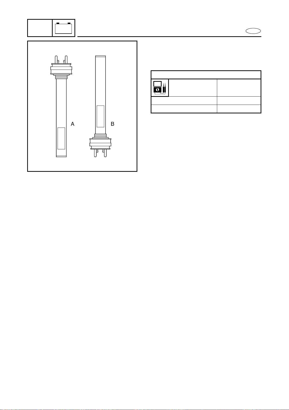
7-31
E
–+
ELEC
INDICATION SYSTEM
FUEL LEVEL SENSOR
1. Measure:
● Fuel level sensor resistance
Out of specification → Replace.
White/blue (W/L) – Black (B)
Float position Resistance (Ω)
A 757–803
B 0–8
MULTIFUNCTION METER
Multifunction meter
1. Check:
● Multifunction meter
Cracked meter housing → Replace
the multifunction meter.
Meter is fogged/shows signs of water
intrusion → Replace the multifunction
meter.
MULTIFUNCTION METER REMOVAL
Refer to “STEERING CONSOLE
COVER” in chapter 8.
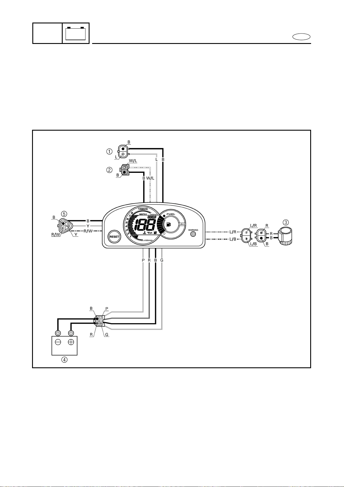
7-32
E
–+
ELEC
INDICATION SYSTEM
Display function
1. Check:
● Display function
Not operate → Replace the multifunc-
tion meter.
1 Oil level sensor
2 Fuel level sensor
3 Buzzer
4 Battery
5 Speed sensor
B : Black
G : Green
L : Blue
P : Pink
R : Red
Y : Yellow
L/B : Blue/black
L/R : Blue/red
R/W : Red/white
W/L : White/blue
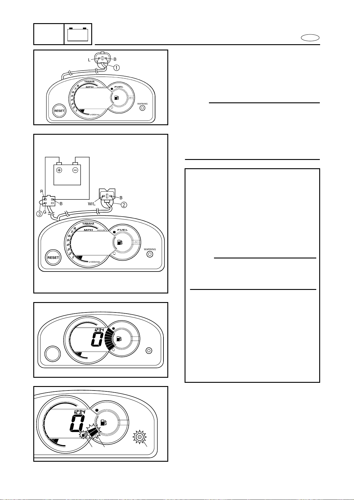
7-33
E
–+
ELEC
INDICATION SYSTEM
Fuel level gauge
1. Check:
● Fuel level gauge
Not operating → Replace the multi-
function meter.
NOTE:
When inspecting the multifunction meter
unit or emptying the oil tank, connect the
blue and black terminals (white two-pin
connector) with a jumper lead 1 to prevent
the oil warning indicator from being acti-
vated.
Checking steps:
● Supply DC 12 voltage to the white
four-pin connector (+: red, –: black)
with a battery.
● Disconnect the green two-pin connec-
tor (white/blue and black leads).
● Connect the white/blue and black ter-
minals with a jumper lead 2.
● Connect the green and red terminals
with a jumper lead 3.
NOTE:
If the jumper lead is installed for more
than 30 seconds, the display will auto-
matically turn off.
● Check the fuel level segments is full
indicated.
● Remove the jumper lead 2 from the
green two-pin connector.
● Disconnect the jumper lead 3 and
then connect it to green and red ter-
minal again.
● Make sure the fuel level segment 4,
fuel symbol 5 and “WARNING” lamp
6 blinks, and the buzzer sounds inter-
mittently.
RESET
WARNING
YAMAHA
8
7
6
5
4
3
2
1
MPH
FUEL
HOUR
x1000r/min
MULTI
DISPLAY
WARNING
YAMAHA
8
7
6
5
4
3
2
1
MPH
FUEL
HOUR
x1000r/min
MULTI
DISPLAY
6
5
4
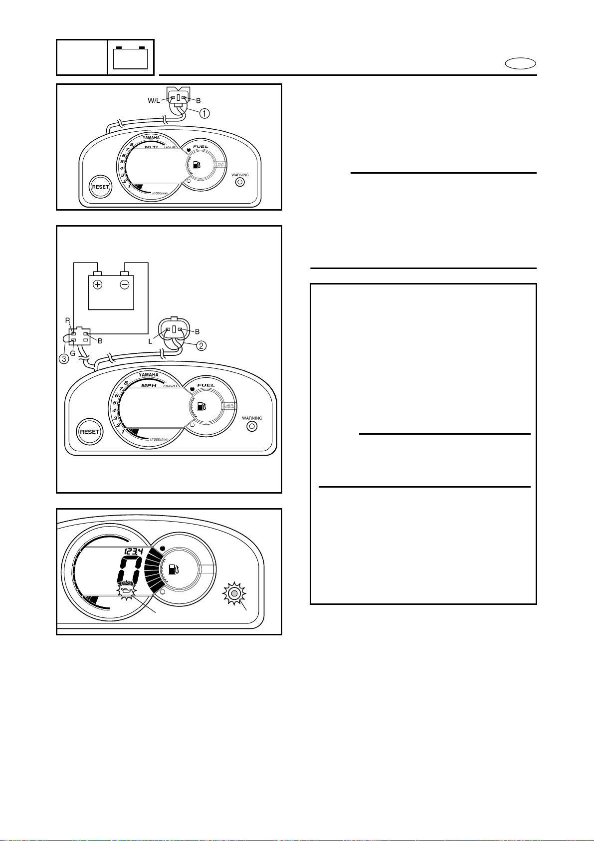
7-34
E
–+
ELEC
INDICATION SYSTEM
Oil level gauge
1. Check:
● Oil level gauge
Not operating → Replace the multi-
function meter.
NOTE:
When inspecting the multifunction meter
unit or emptying the fuel tank, connect the
white/blue and black terminals (green two-
pin connector) with a jumper lead 1 to pre-
vent the fuel warning indicator from being
activated.
Checking steps:
● Supply DC 12 voltage to the white
four-pin connector (+: red, –: black)
with a battery.
● Disconnect the white two-pin connec-
tor (blue and black leads).
● Connect the blue and black terminals
with a jumper lead 2.
● Connect the green and red terminals
with a jumper lead 3.
NOTE:
If the jumper lead is installed for more
than 30 seconds, the display will auto-
matically turn off.
● Remove the jumper lead 2 from the
white two-pin connector.
● Disconnect the jumper lead 3 and
then connect it to green and red ter-
minal again.
● Make sure the oil symbol 4 and
“WARNING” lamp 5 blinks, and the
buzzer sounds intermittently.
WARNING
YAMAHA
8
7
6
5
4
3
2
1
MPH
FUEL
HOUR
x1000r/min
MULTI
DISPLAY
5
4
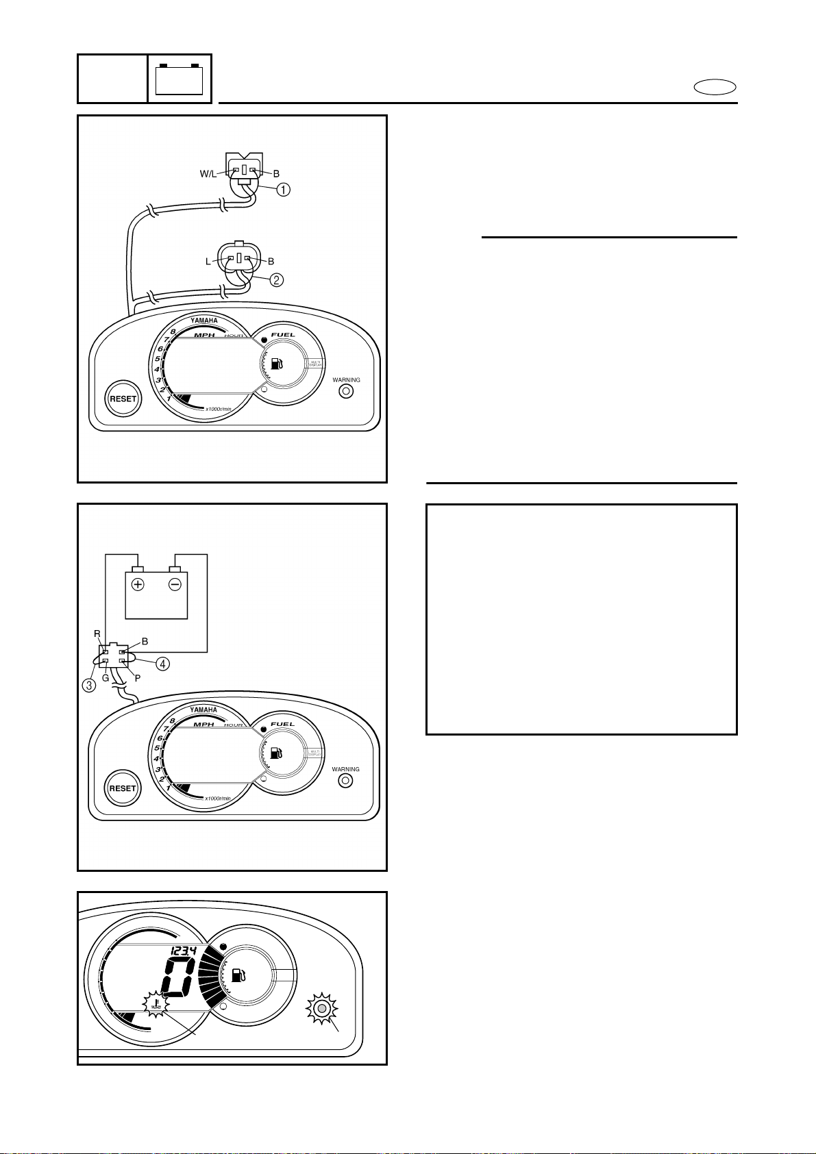
7-35
E
–+
ELEC
INDICATION SYSTEM
Overheat warning indicator
1. Check:
● Overheat warning indicator
Not operating → Replace the multi-
function meter.
NOTE:
● When inspecting the multifunction meter
unit or emptying the fuel tank, connect the
white/blue and black terminals (green
two-pin connector) with a jumper lead 1
to prevent the fuel warning indicator from
being activated.
● When inspecting the multifunction meter
unit or emptying the oil tank, connect the
blue and black terminals (white two-pin
connector) with a jumper lead 2 to pre-
vent the oil warning indicator from being
activated.
Checking steps:
● Supply DC 12 voltage to the white
four-pin connector (+: red, –: black)
with a battery.
● Connect the green and red terminals
with a jumper lead 3.
● Connect the pink and black terminals
with a jumper lead 4.
● Make sure the water temperature sym-
bol 5 and “WARNING” lamp 6
blinks, and the buzzer sounds intermit-
tently.
WARNING
YAMAHA
8
7
6
5
4
3
2
1
MPH
FUEL
HOUR
x1000r/min
MULTI
DISPLAY
6
5
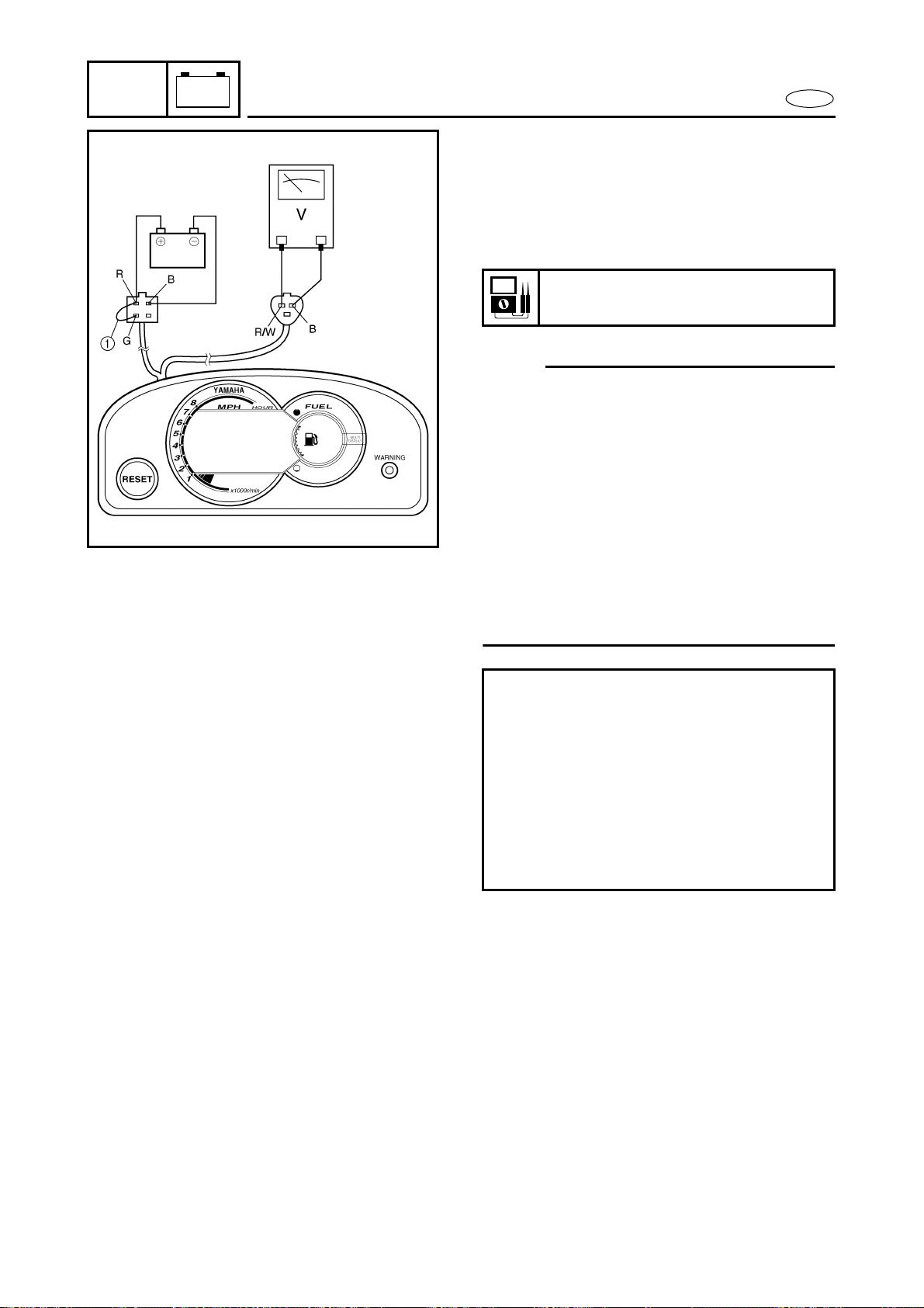
7-36
E
–+
ELEC
INDICATION SYSTEM
Speed meter
1. Check:
● Speed meter output voltage
Within specification → Check the speed
sensor output voltage and pulses.
Out of specification → Replace.
NOTE:
● When inspecting the multifunction meter
unit or emptying the fuel tank, connect the
white/blue and black terminals (green
two-pin connector) with a jumper lead 1
to prevent the fuel warning indicator from
being activated.
● When inspecting the multifunction meter
unit or emptying the oil tank, connect the
blue and black terminals (white two-pin
connector) with a jumper lead 2 to pre-
vent the oil warning indicator from being
activated.
Speed meter output voltage:
10.5 V
Checking steps:
● Supply DC 12 voltage to the white
four-pin connector (+: red, –: black)
with a battery.
● Connect the green and red terminals
with a jumper lead 1.
● Measure the voltage on the speed sen-
sor connector (white three-pin connec-
tor) between the red/white and black
leads.
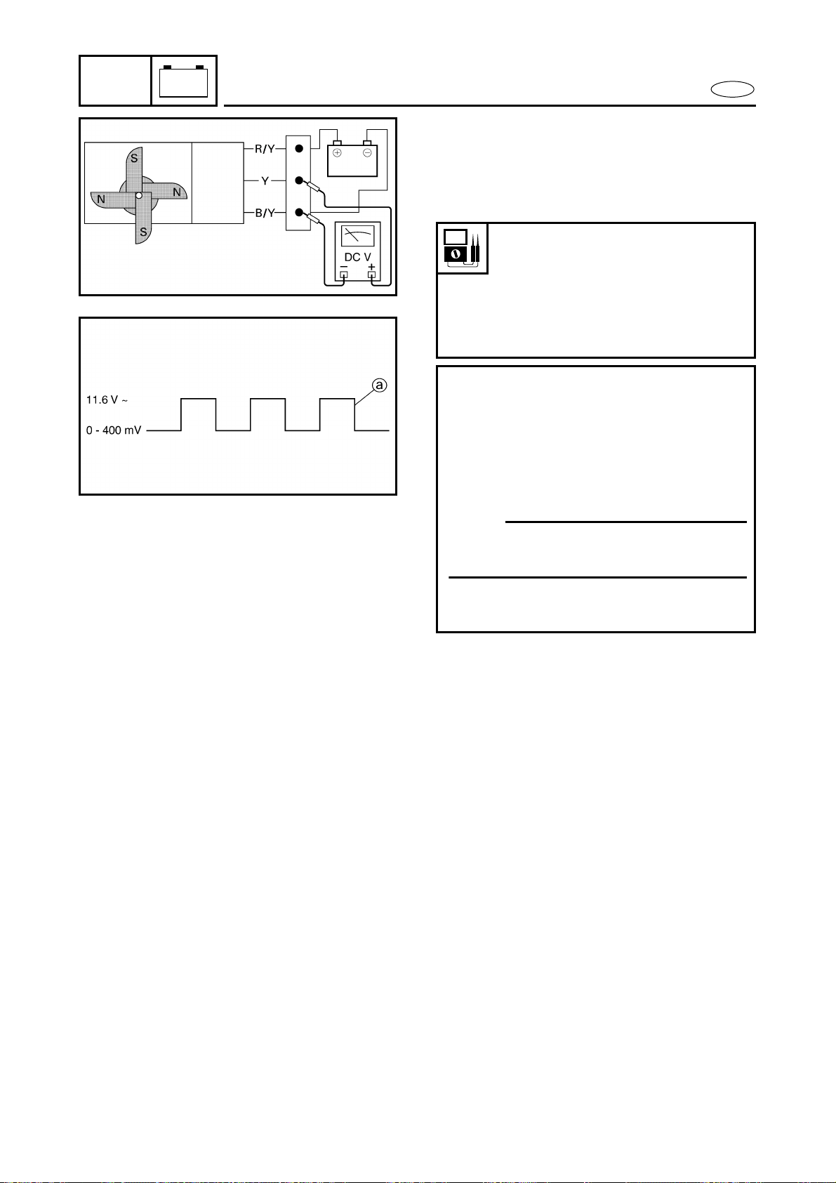
7-37
E
–+
ELEC
INDICATION SYSTEM
Speed sensor
1. Check:
● Speed sensor output voltage and
pulses
Out of specification → Replace.
Speed sensor output voltage
(dependant on the paddle wheel
position):
Less than 400 mV/
More than 11.6 V
Output pulse:
2 pulses/one-full turn
Checking steps:
● Apply DC 12 voltage to the white
three-pin connector (between the red/
yellow and black/yellow leads).
● Rotate the paddle wheel by hand and
measure the voltage between the yel-
low and black/yellow leads.
NOTE:
As the paddle wheel is rotated, a square-
wave voltage signal a is produced.
● Two pulses occur every time the pad-
dle wheel makes one-full turn.


E
HULL
HOOD
CHAPTER 8
HULL AND HOOD
HANDLEBAR................................................................................................... 8-1
EXPLODED DIAGRAM............................................................................. 8-1
REMOVAL AND INSTALLATION CHART ............................................... 8-1
SERVICE POINTS ..................................................................................... 8-7
Handlebar inspection........................................................................ 8-7
Handlebar switch inspection............................................................ 8-7
Handlebar assembly installation ..................................................... 8-7
QSTS GRIP.................................................................................................... 8-10
EXPLODED DIAGRAM........................................................................... 8-10
REMOVAL AND INSTALLATION CHART ............................................. 8-10
SERVICE POINTS ................................................................................... 8-12
QSTS cable inspection.................................................................... 8-12
QSTS grip inspection...................................................................... 8-12
STEERING COLUMN.................................................................................... 8-13
EXPLODED DIAGRAM........................................................................... 8-13
REMOVAL AND INSTALLATION CHART ............................................. 8-13
SERVICE POINTS ................................................................................... 8-16
Steering column bushing inspection ............................................ 8-16
REMOTE CONTROL CABLES AND SPEED SENSOR LEAD ...................... 8-17
EXPLODED DIAGRAM........................................................................... 8-17
REMOVAL AND INSTALLATION CHART ............................................. 8-17
SERVICE POINTS ................................................................................... 8-20
Remote control cables inspection ................................................. 8-20
Steering cable (jet pump side) installation ................................... 8-20
Steering cable stopper installation................................................ 8-20
QSTS cable (jet pump side) installation........................................ 8-21
QSTS cable stopper installation .................................................... 8-21
FRONT HOOD ............................................................................................... 8-22
EXPLODED DIAGRAM........................................................................... 8-22
REMOVAL AND INSTALLATION CHART ............................................. 8-22
STEERING CONSOLE COVER ..................................................................... 8-24
EXPLODED DIAGRAM........................................................................... 8-24
REMOVAL AND INSTALLATION CHART ............................................. 8-24

E
1
2
3
4
5
6
7
8
9
HULL
HOOD
BUZZER AND HOOD LOCK ......................................................................... 8-28
EXPLODED DIAGRAM........................................................................... 8-28
REMOVAL AND INSTALLATION CHART ............................................. 8-28
HOSES........................................................................................................... 8-31
EXPLODED DIAGRAM........................................................................... 8-31
REMOVAL AND INSTALLATION CHART ............................................. 8-31
SERVICE POINTS ................................................................................... 8-33
Check valve inspection ................................................................... 8-33
Ventilation hose installation........................................................... 8-33
SEATS AND HAND GRIP ............................................................................. 8-34
EXPLODED DIAGRAM........................................................................... 8-34
REMOVAL AND INSTALLATION CHART ............................................. 8-34
SERVICE POINTS ................................................................................... 8-36
Seat lock inspection ........................................................................ 8-36
BATTERY BOX.............................................................................................. 8-37
EXPLODED DIAGRAM........................................................................... 8-37
REMOVAL AND INSTALLATION CHART ............................................. 8-37
EXHAUST SYSTEM...................................................................................... 8-39
EXPLODED DIAGRAM........................................................................... 8-39
REMOVAL AND INSTALLATION CHART ............................................. 8-39
SERVICE POINTS ................................................................................... 8-41
Exhaust system inspection............................................................. 8-41
Exhaust component parts sub-assembly...................................... 8-41
DECK AND HULL.......................................................................................... 8-42
EXPLODED DIAGRAM........................................................................... 8-42
REMOVAL AND INSTALLATION CHART ............................................. 8-42
ENGINE MOUNT .......................................................................................... 8-44
EXPLODED DIAGRAM........................................................................... 8-44
REMOVAL AND INSTALLATION CHART ............................................. 8-44
HULL REPAIR ......................................................................................... 8-45
Shallow scratches ........................................................................... 8-45
Deep scratches ................................................................................ 8-45
Cracks and punctures ..................................................................... 8-46
Insert nut.......................................................................................... 8-47
Graphic removal.............................................................................. 8-49
Graphic installation......................................................................... 8-49

8-1
E
HULL
HOOD
HANDLEBAR
HANDLEBAR
EXPLODED DIAGRAM
REMOVAL AND INSTALLATION CHART
Step Procedure/Part name Q’ty Service points
HANDLEBAR COVER REMOVAL Follow the left “Step” for removal.
1 Screw 4
2 Handlebar cover 1
3 Screw 4
4 Handlebar cover stay 1
5 Spiral tube 1
6 Band 1
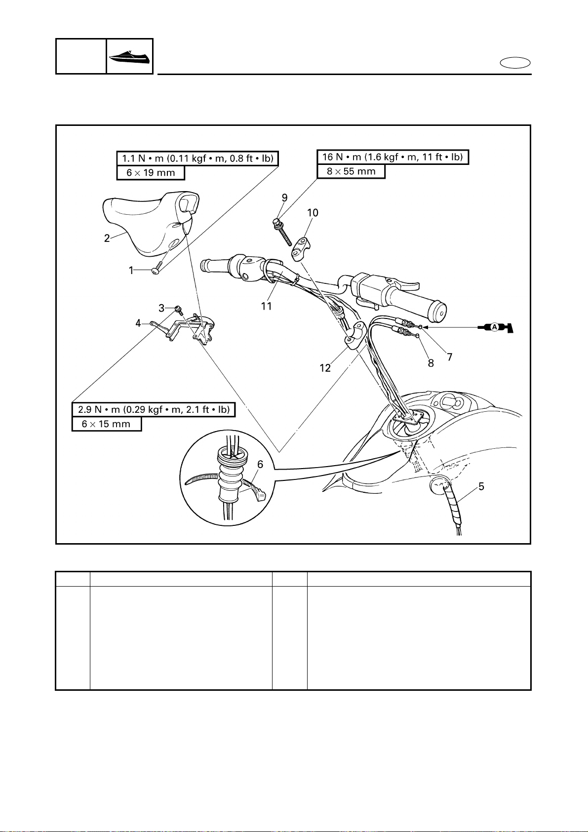
8-2
E
HULL
HOOD
HANDLEBAR
EXPLODED DIAGRAM
Step Procedure/Part name Q’ty Service points
7 Throttle cable 1
8 Choke cable 1
9 Bolt 4
10 Upper handlebar holder 2
11 Handlebar assembly 1
12 Lower handlebar holder 2
Reverse the removal steps for installation.
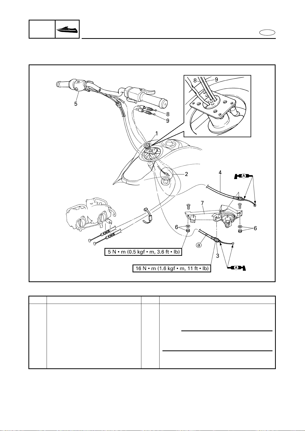
8-3
E
HULL
HOOD
HANDLEBAR
EXPLODED DIAGRAM
REMOVAL AND INSTALLATION CHART
Step Procedure/Part name Q’ty Service points
HANDLEBAR REMOVAL Follow the left “Step” for removal.
QSTS cable (to jet nozzle) Refer to “REMOTE CONTROL CABLES
AND SPEED SENSOR LEAD”.
1 Grommet 1
NOTE:
Apply soapy water to the grommet for
easier installation.
2 Handlebar switch coupler 2
3 QSTS cable 2 1 with white tape a
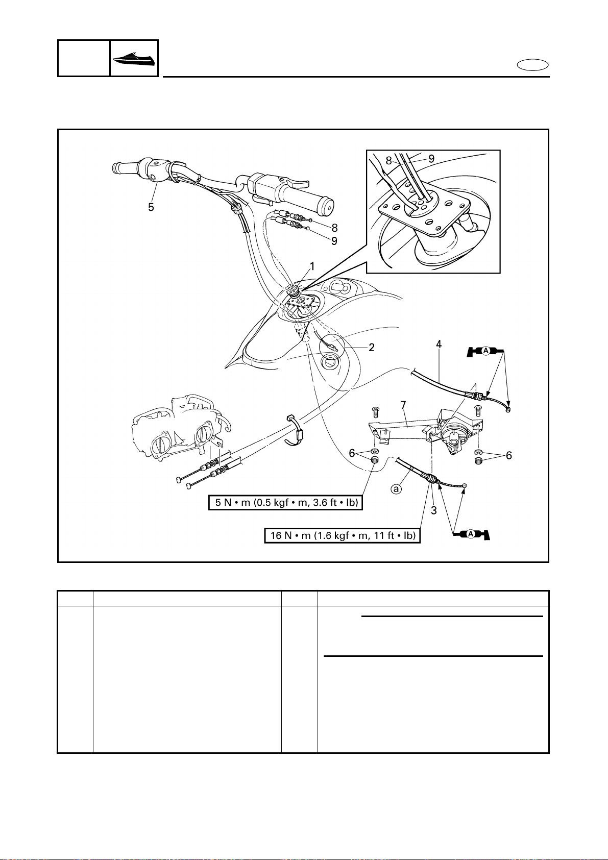
8-4
E
HULL
HOOD
HANDLEBAR
EXPLODED DIAGRAM
Step Procedure/Part name Q’ty Service points
4 QSTS cable 1 1
NOTE:
Route the QSTS cables behind of the oil
filler hose.
5 Handlebar assembly 1
6 Nut/washer 2/2
7 QSTS converter 1
8 Throttle cable 1
9 Choke cable 1
Reverse the removal steps for installation.
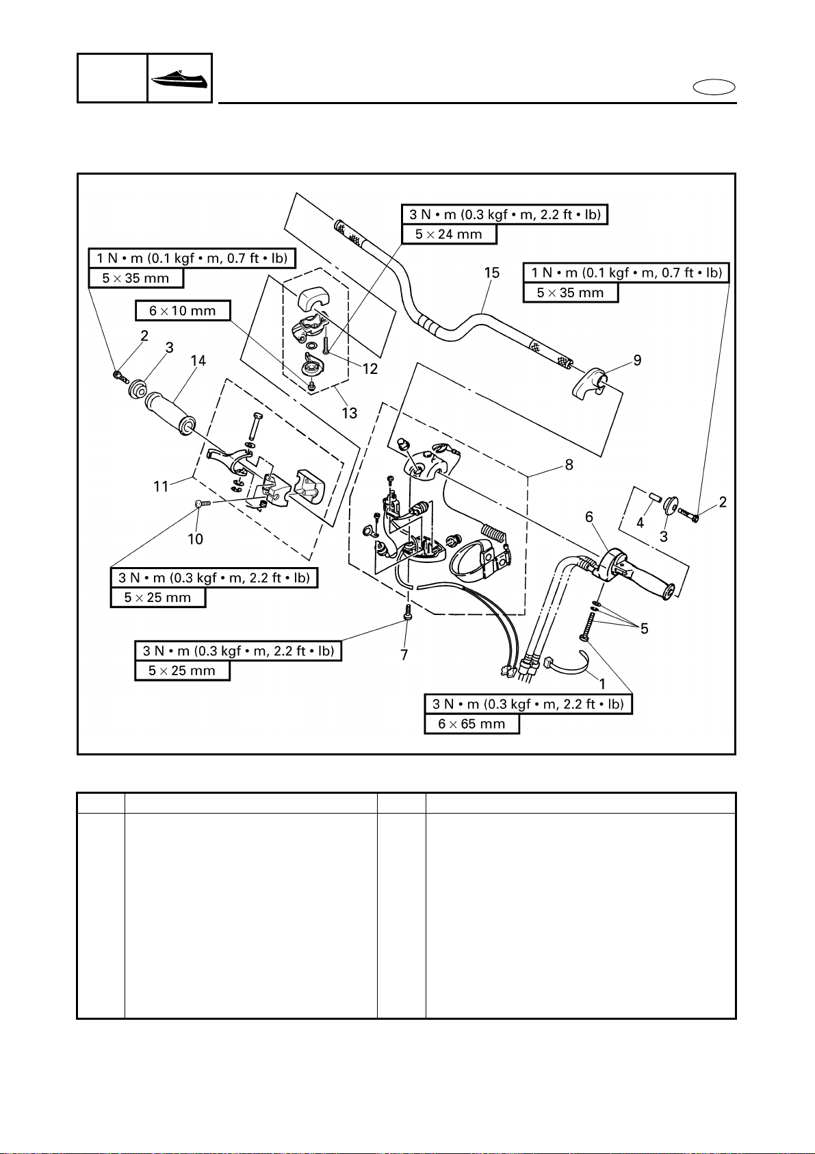
8-5
E
HULL
HOOD
HANDLEBAR
EXPLODED DIAGRAM
REMOVAL AND INSTALLATION CHART
Step Procedure/Part name Q’ty Service points
HANDLEBAR DISASSEMBLY Follow the left “Step” for disassembly.
1 Band 1
2 Bolt 2
3 Grip end 2
4 Spacer 1
5 Screw/washer/spring washer 1/1/1
6 QSTS grip assembly 1
7 Screw 2
8 Handlebar switch assembly 1
9 Cable holder 1
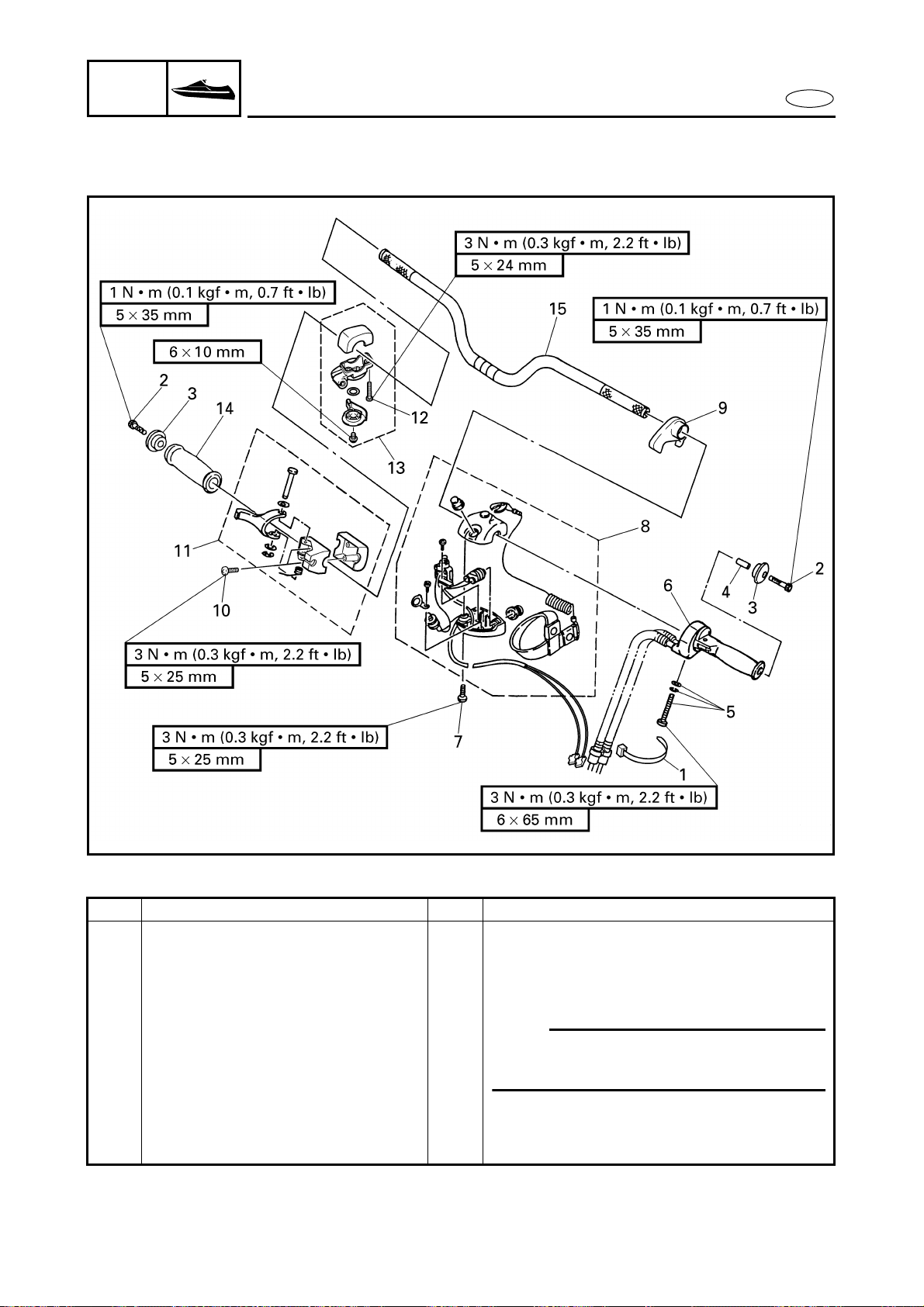
8-6
E
HULL
HOOD
HANDLEBAR
EXPLODED DIAGRAM
Step Procedure/Part name Q’ty Service points
10 Screw 2
11 Throttle lever assembly 1
12 Screw 2
13 Choke lever assembly 1
14 Handlebar grip 1
NOTE:
Apply adhesive to the handlebar and the
inner surface of the handlebar grip.
15 Handlebar 1
Reverse the disassembly steps for
assembly.

8-7
E
HULL
HOOD
HANDLEBAR
SERVICE POINTS
Handlebar inspection
1. Inspect:
● Handlebar
Bends/cracks/damage → Replace.
Handlebar switch inspection
Refer to “IGNITION SYSTEM” and
“STARTING SYSTEM” in chapter 7.
Handlebar assembly installation
1. Adjust:
● QSTS cable length a
NOTE:
● Before adjusting the QSTS cables, set the
control grip to the neutral position.
● Adjust the QSTS cable lengths a to the
specified length and be sure to take up
any slack.
QSTS cable length:
77 ± 0.5 mm (3.03 ± 0.02 in)
2. Install:
● Upper handlebar holder 1
NOTE:
● Align the punch marks a on the handle-
bar with the top surface of the handlebar
holder.
● The upper handlebar holder should be
installed with the punch mark b facing
forward.
CAUTION:
Clearance c should be narrower than
clearance d.
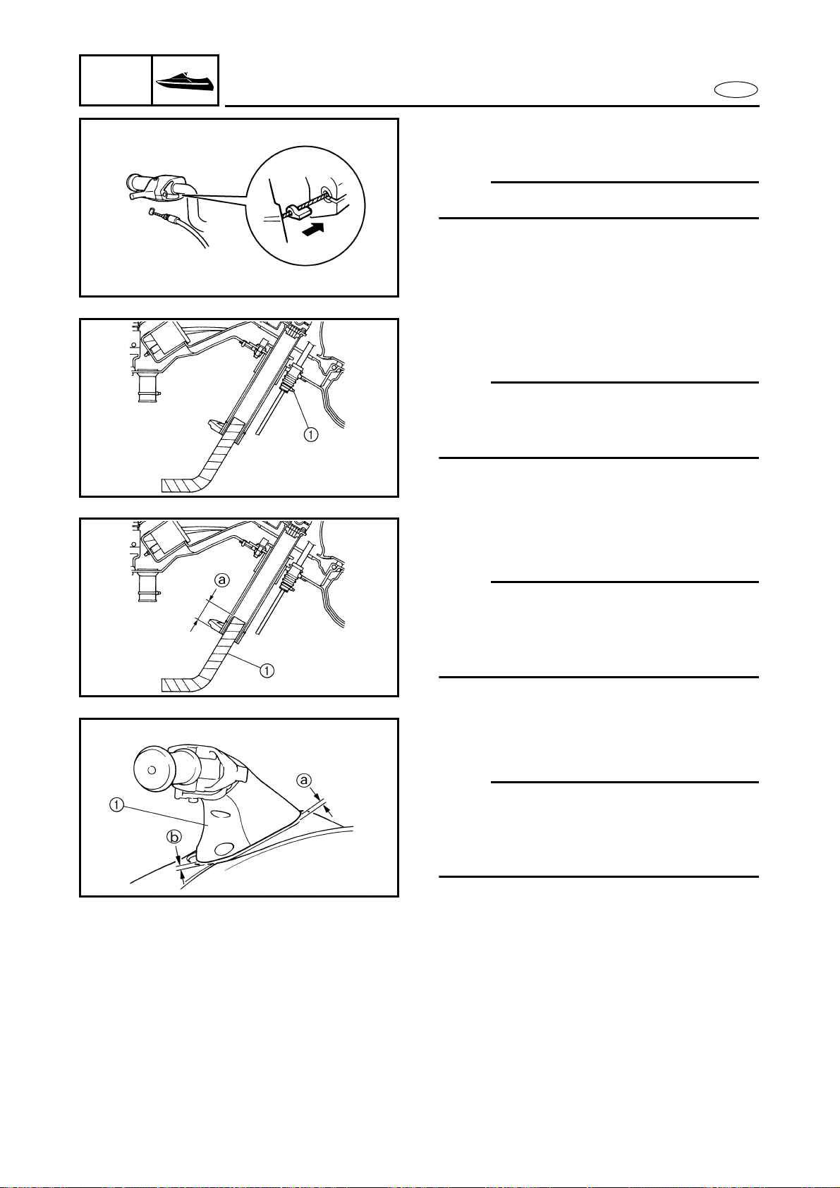
8-8
E
HULL
HOOD
HANDLEBAR
3. Install:
● Throttle cable
NOTE:
Fit the seal into the glove in the bracket.
4. Install:
● Band 1
NOTE:
After inserting the QSTS cables into the
grommet, tie the end of grommet with the
band.
5. Install:
● Spiral tube 1
NOTE:
Be sure to install the spiral tube, containing
the throttle cable, choke cable and handle-
bar switch lead, at least 50 mm (1.97 in) a
into the steering column.
6. Install:
● Handlebar cover 1
NOTE:
When the handlebar cover is in contact with
the steering console cover, adjust the han-
dlebar mount angle so that the clearance a
and b are equal.

8-9
E
HULL
HOOD
HANDLEBAR
7. Adjust:
● Choke lever operation
Refer to “CONTROL SYSTEM” in
chapter 3.
8. Adjust:
● Throttle lever free play
Refer to “CONTROL SYSTEM” in
chapter 3.
9. Adjust:
● QSTS cable
Refer to “CONTROL SYSTEM” in
chapter 3.

8-10
E
HULL
HOOD
QSTS GRIP
QSTS GRIP
EXPLODED DIAGRAM
REMOVAL AND INSTALLATION CHART
Step Procedure/Part name Q’ty Service points
QSTS GRIP DISASSEMBLY Follow the left “Step” for disassembly.
QSTS grip assembly Refer to “HANDLEBAR”.
1 Screw/washer 1/1
2 Cover 1
3 Ball 2
4 Spring 2
5 QSTS cable 1 1
6 QSTS cable 2 1 with white tape a
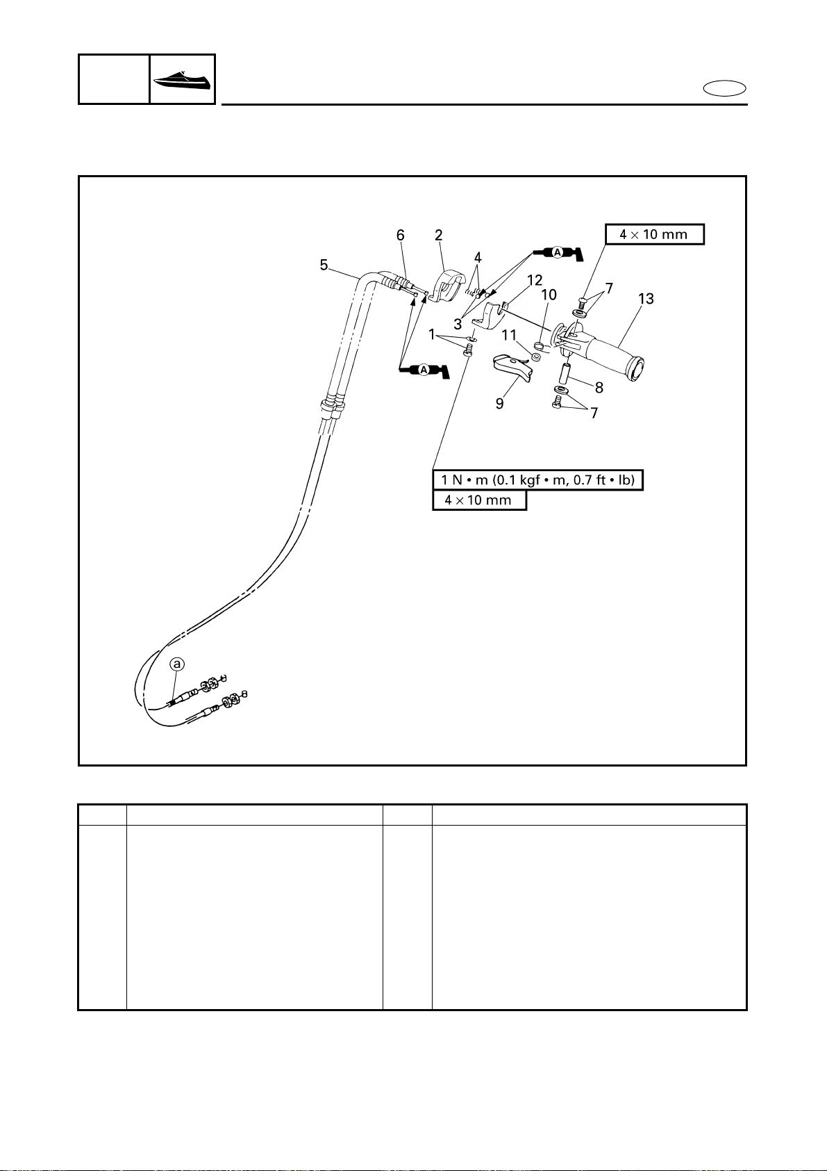
8-11
E
HULL
HOOD
QSTS GRIP
EXPLODED DIAGRAM
Step Procedure/Part name Q’ty Service points
7 Screw/washer 2/2
8 Collar 1
9 QSTS shift lock lever 1
10 Spring 1
11 Spacer 1
12 QSTS cable housing cover 1
13 QSTS shift grip 1
Reverse the disassembly steps for
assembly.

8-12
E
HULL
HOOD
QSTS GRIP
SERVICE POINTS
QSTS cable inspection
1. Inspect:
● QSTS cables
Frays/kinks/rough movement →
Replace.
QSTS grip inspection
1. Inspect:
● QSTS grip
Damage/wear → Replace.
8-13
E
HULL
HOOD
STEERING COLUMN
STEERING COLUMN
EXPLODED DIAGRAM
REMOVAL AND INSTALLATION CHART
Step Procedure/Part name Q’ty Service points
STEERING COLUMN REMOVAL Follow the left “Step” for removal.
Steering console cover assembly Refer to “STEERING CONSOLE COVER”.
Steering cable end Refer to “REMOTE CONTROL CABLES
AND SPEED SENSOR LEAD”.
1 Nut 4
2 Plate 1
3 Steering column assembly 1
4 Rubber seal 1
Reverse the removal steps for installation.
1
2
3
4
16 N • m (1.6 kgf
• m, 11 ft • Ib)
8-14
E
HULL
HOOD
STEERING COLUMN
EXPLODED DIAGRAM
REMOVAL AND INSTALLATION CHART
*: Be sure to install the same number of shim(s) as installed originally at factory.
Step Procedure/Part name Q’ty Service points
STEERING COLUMN
DISASSEMBLY
Follow the left “Step” for disassembly.
1 Grommet 1
2 Bolt/washer/nut 1/2/1
3 Steering arm 1
4 Shim *
8 × 60 mm
16 N • m (1.6 kgf
• m, 11 ft • Ib)
5 N • m (0.5 kgf
• m, 3.6 ft • Ib)
26 N • m (2.6 kgf
• m, 19 ft • Ib)
2
7
5
4
3
2
1
8
6
7

8-15
E
HULL
HOOD
STEERING COLUMN
EXPLODED DIAGRAM
Step Procedure/Part name Q’ty Service points
5 Washer 1
6 Steering column 1
7 Bushing 2
8 Steering column housing 1
Reverse the disassembly steps for
assembly.
8 × 60 mm
16 N • m (1.6 kgf
• m, 11 ft • Ib)
5 N • m (0.5 kgf
• m, 3.6 ft • Ib)
26 N • m (2.6 kgf
• m, 19 ft • Ib)
2
7
5
4
3
2
1
8
6
7
8-16
E
HULL
HOOD
STEERING COLUMN
SERVICE POINTS
Steering column bushing inspection
1. Inspect:
● Bushings
Damage/wear → Replace.
2. Inspect:
● Steering column inspection
Refer to “CONTROL SYSTEM” in
chapter 3.
8-17
E
HULL
HOOD
REMOTE CONTROL CABLES AND
SPEED SENSOR LEAD
REMOTE CONTROL CABLES AND SPEED SENSOR LEAD
EXPLODED DIAGRAM
REMOVAL AND INSTALLATION CHART
Step Procedure/Part name Q’ty Service points
REMOTE CONTROL CABLES
AND SPEED SENSOR LEAD
REMOVAL
Follow the left “Step” for removal.
1 Speed sensor coupler 1
2 Cap 1
3 Nut 1
4 Screw 4
5 Speed sensor 1
6 Steering cable end 1
7 Bolt 1
8 Steering cable holder 1

8-18
E
HULL
HOOD
REMOTE CONTROL CABLES AND
SPEED SENSOR LEAD
EXPLODED DIAGRAM
Step Procedure/Part name Q’ty Service points
9 Cap 1
10 Nut 1
11 Steering cable 1
12 Nut 1
13 Pin 1
14 QSTS cable end 1
15 Cap 1
16 Nut 1
17 QSTS cable 1
Reverse the removal steps for installation.
8-19
E
HULL
HOOD
REMOTE CONTROL CABLES AND
SPEED SENSOR LEAD
EXPLODED DIAGRAM
REMOVAL AND INSTALLATION CHART
Step Procedure/Part name Q’ty Service points
SPEED SENSOR DISASSEMBLY Follow the left “Step” for disassembly.
1 Paddle wheel set 1
2 Speed sensor housing 1
Reverse the disassembly steps for
assembly.
FWD
1
2
Not reusable
8-20
E
HULL
HOOD
REMOTE CONTROL CABLES AND
SPEED SENSOR LEAD
SERVICE POINTS
WARNING
When routing the cables, do not grasp the
cable by the outer crimped sheath or steel
end. This could deform or loosen the cable
end due to extreme angles and or pressure.
Always hold the cables by the bracket or
outer cover below the crimp.
If a cable becomes damaged replace it.
Never attempt to repair a damaged cable.
Remote control cables inspection
1. Inspect:
● Steering cable
● QSTS cable
Frays/kinks/rough movement →
Replace.
Steering cable (jet pump side) installation
1. Install:
● Steering cable a
WARNING
The steering cable must be screwed in at
least 8 mm (0.31 in).
Steering cable set length
(jet pump side):
13.5–15.5 mm (0.53–0.61 in)
Steering cable stopper installation
1. Install:
● Steering cable stopper
WARNING
Be sure to fit the steering cable into the
glove 1 in the steering cable bracket.
1
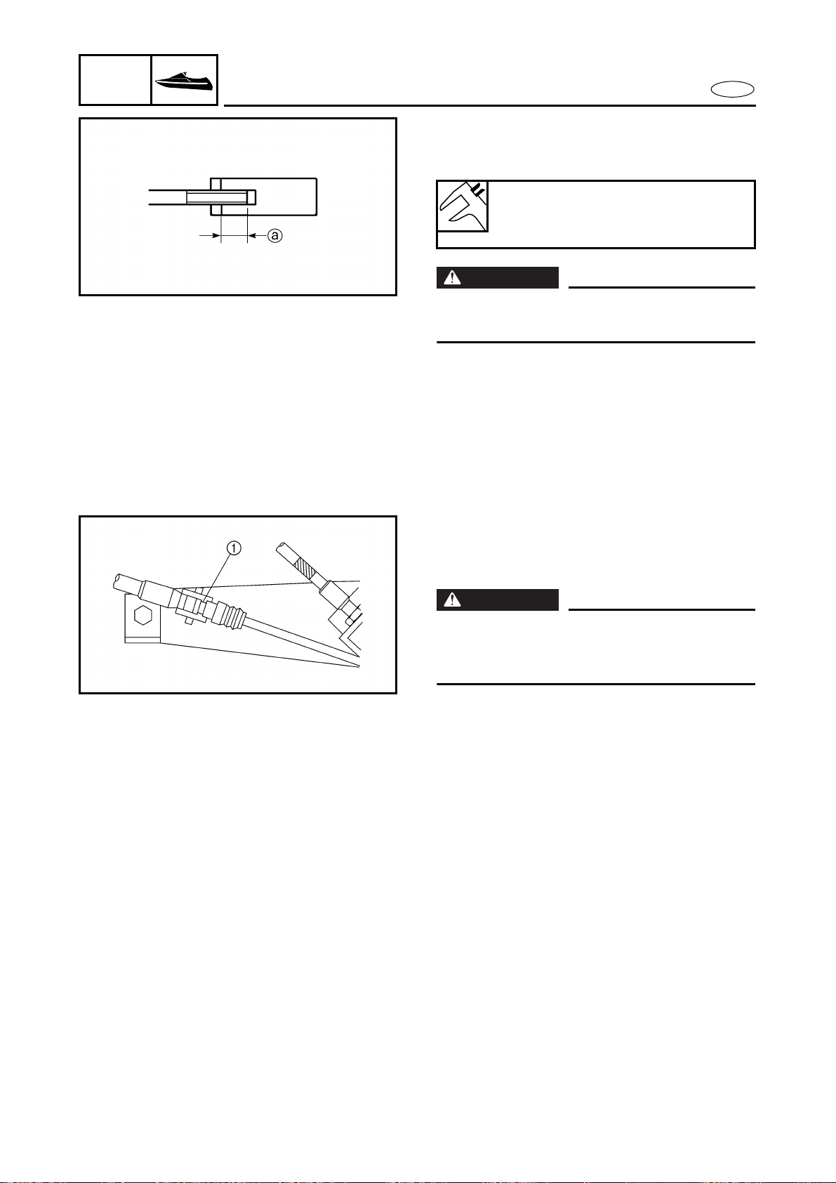
8-21
E
HULL
HOOD
REMOTE CONTROL CABLES AND
SPEED SENSOR LEAD
QSTS cable (jet pump side) installation
1. Install:
● QSTS cable (jet pump side) a
WARNING
The QSTS cable must be screwed in more
than 8 mm (0.31 in).
QSTS cable set length
(jet pump side):
12.0–14.0 mm (0.47–0.55 in)
QSTS cable stopper installation
1. Install:
● QSTS cable stopper
WARNING
Be sure to fit the projection 1 on the QSTS
cable stopper into the glove in the outer
cable.

8-22
E
HULL
HOOD
FRONT HOOD
FRONT HOOD
EXPLODED DIAGRAM
REMOVAL AND INSTALLATION CHART
Step Procedure/Part name Q’ty Service points
FRONT HOOD REMOVAL Follow the left “Step” for removal.
1 Bolt 2
2 Screw 8
3 Seal washer 8
4 Visor 1
5 Pop nut 8
6 Bolt 2
10
9
1
11
2
3
5
8
4
16 N • m (1.6 kgf
• m, 11 ft • Ib)
6 × 14 mm
5 N • m (0.5 kgf
• m, 3.6 ft • Ib)
6 × 14 mm
12 N • m (1.2 kgf
• m, 8.7 ft • Ib)
5 × 20 mm
1 N • m (0.1 kgf
• m, 0.7 ft • Ib)
6
7
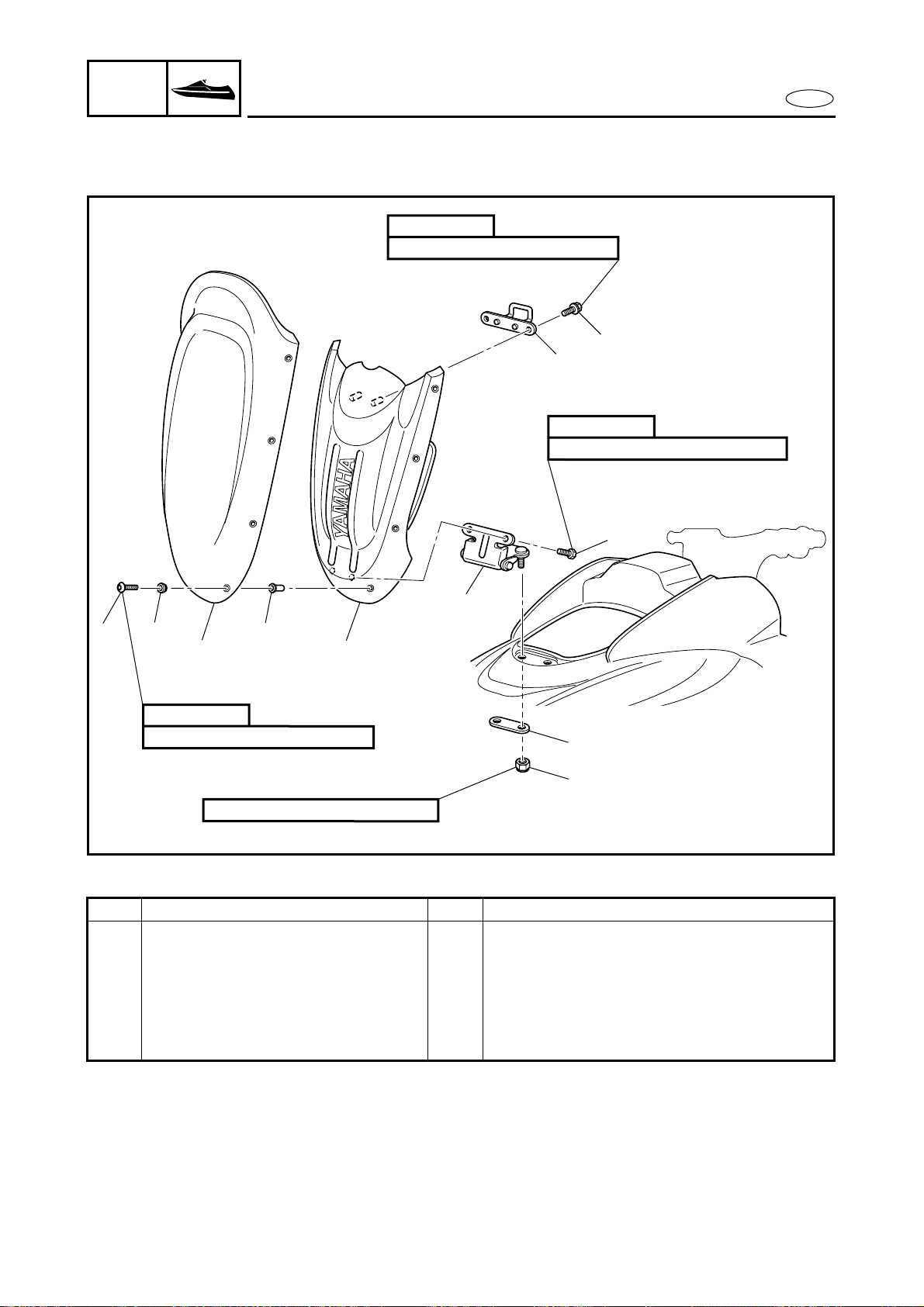
8-23
E
HULL
HOOD
EXPLODED DIAGRAM
Step Procedure/Part name Q’ty Service points
7 Hood lock 1
8 Front hood 1
9 Nut 2
10 Plate 1
11 Hinge assembly 1
Reverse the removal steps for installation.
10
9
1
11
2
3
5
8
4
16 N • m (1.6 kgf
• m, 11 ft • Ib)
6 × 14 mm
5 N • m (0.5 kgf
• m, 3.6 ft • Ib)
6 × 14 mm
12 N • m (1.2 kgf
• m, 8.7 ft • Ib)
5 × 20 mm
1 N • m (0.1 kgf
• m, 0.7 ft • Ib)
6
7
FRONT HOOD
8-24
E
HULL
HOOD
STEERING CONSOLE COVER
STEERING CONSOLE COVER
EXPLODED DIAGRAM
REMOVAL AND INSTALLATION CHART
Step Procedure/Part name Q’ty Service points
STEERING CONSOLE COVER
REMOVAL
Follow the left “Step” for removal.
Handlebar assembly Refer to “HANDLEBAR”.
Knob (fuel cock) Refer to “FUEL COCK AND FUEL FILTER”
in chapter 4.
1 Band 1
2 Multifunction meter coupler 5
3 Nut/washer 2/2
4 Bolt/washer 4/4
5 Screw 2
5 × 19 mm
2 N • m (0.2 kgf
• m, 1.4 ft • Ib)
8 × 25 mm
16 N • m (1.6 kgf
• m, 11 ft • Ib)
5 N • m (0.5 kgf
• m, 3.6 ft • Ib)
1
7
2
9
8
5
6
4
6 × 25 mm
3 N • m (0.3 kgf
• m, 2.2 ft • Ib)
3
8-25
E
HULL
HOOD
STEERING CONSOLE COVER
EXPLODED DIAGRAM
Step Procedure/Part name Q’ty Service points
6 Plate 1
7 Nut/washer 2/2
8 Bolt/square-ring 2/2
9 Steering console cover assembly 1
NOTE:
Remove the oil filler cap to remove the
steering console cover assembly easier.
Reverse the removal steps for installation.
5 × 19 mm
2 N • m (0.2 kgf
• m, 1.4 ft • Ib)
8 × 25 mm
16 N • m (1.6 kgf
• m, 11 ft • Ib)
5 N • m (0.5 kgf
• m, 3.6 ft • Ib)
1
7
2
9
8
5
6
4
6 × 25 mm
3 N • m (0.3 kgf
• m, 2.2 ft • Ib)
3
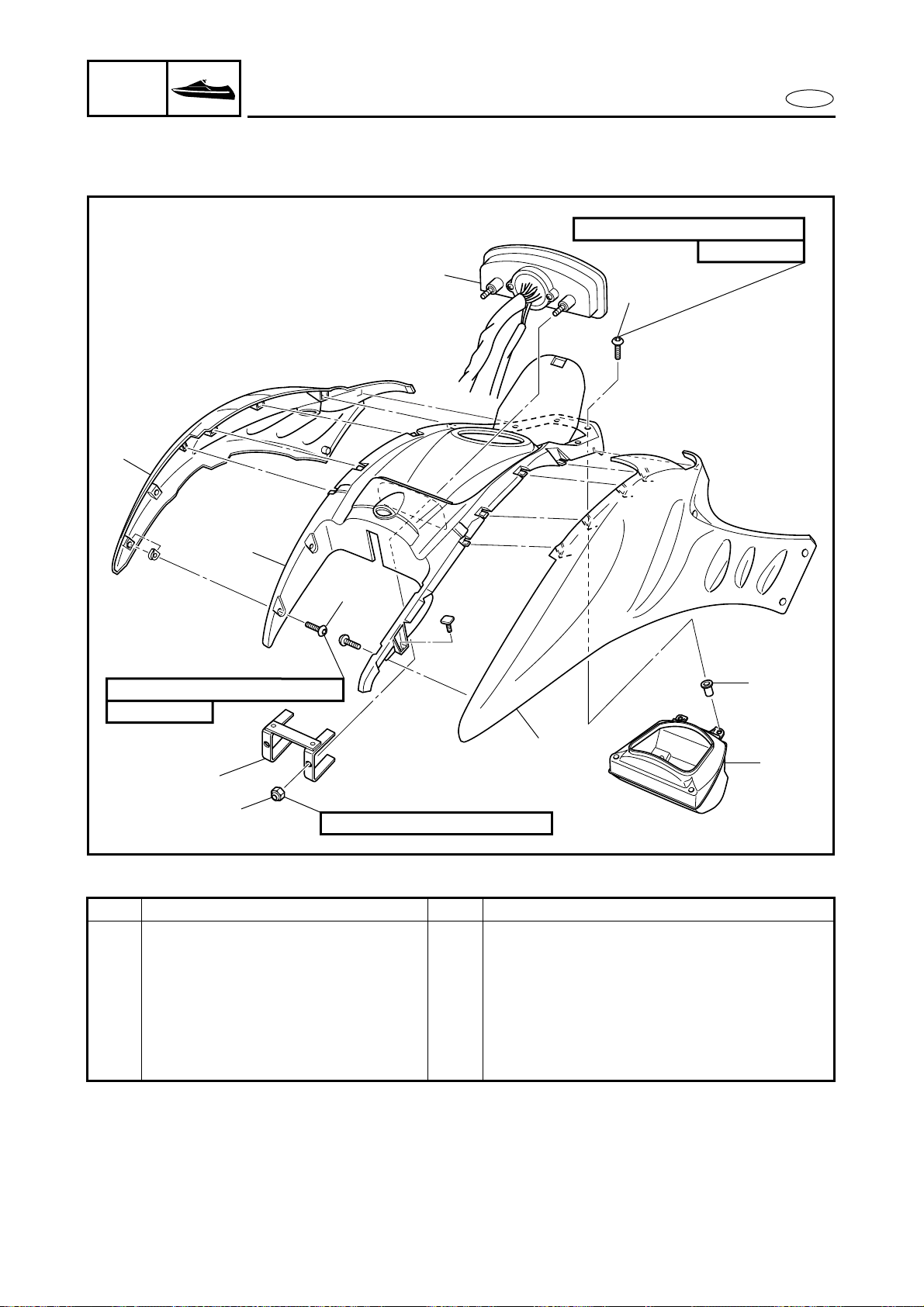
8-26
E
HULL
HOOD
STEERING CONSOLE COVER
EXPLODED DIAGRAM
REMOVAL AND INSTALLATION CHART
Step Procedure/Part name Q’ty Service points
STEERING CONSOLE COVER
DISASSEMBLY
Follow the left “Step” for disassembly.
1 Screw 4
2 Side cover 2
3 Nut 2
4 Holder 1
5 Multifunction meter 1
6
8
7
2 N • m (0.2 kgf
• m, 1.4 ft • Ib)
6 × 18 mm
3 N • m (0.3 kgf
• m, 2.2 ft • Ib)
4
3
1
9
2
2
5
5 × 20 mm
1 N • m (0.1 kgf
• m, 0.7 ft • Ib)
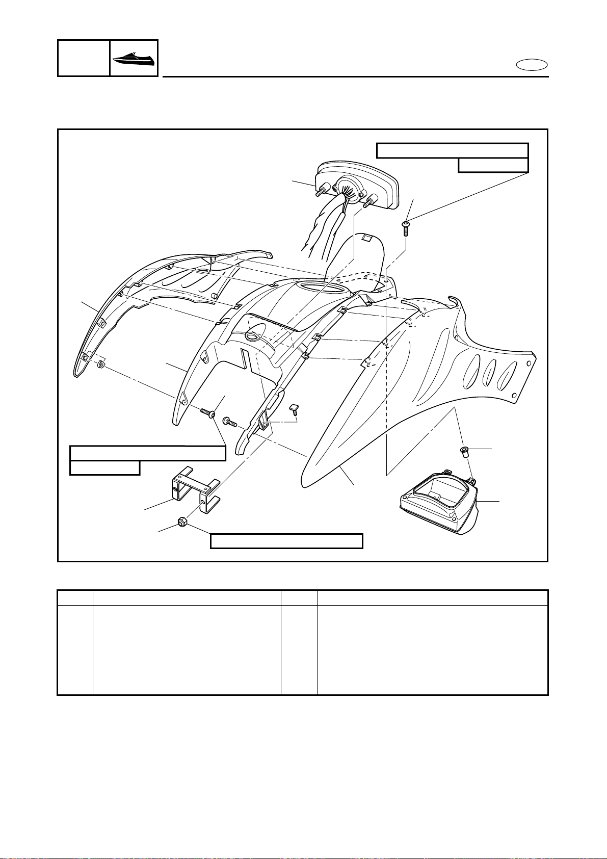
8-27
E
HULL
HOOD
STEERING CONSOLE COVER
EXPLODED DIAGRAM
Step Procedure/Part name Q’ty Service points
6 Screw 4
7 Glove compartment 1
8 Pop nut 4
9 Steering console cover 1
Reverse the disassembly steps for
assembly.
6
8
7
2 N • m (0.2 kgf
• m, 1.4 ft • Ib)
6 × 18 mm
3 N • m (0.3 kgf
• m, 2.2 ft • Ib)
4
3
1
9
2
2
5
5 × 20 mm
1 N • m (0.1 kgf
• m, 0.7 ft • Ib)
8-28
E
HULL
HOOD
BUZZER AND HOOD LOCK
BUZZER AND HOOD LOCK
EXPLODED DIAGRAM
REMOVAL AND INSTALLATION CHART
Step Procedure/Part name Q’ty Service points
BUZZER AND HOOD LOCK
REMOVAL
Follow the left “Step” for removal.
Steering console cover assembly Refer to “STEERING CONSOLE COVER”.
Steering cable Refer to “REMOTE CONTROL CABLES
AND SPEED SENSOR LEAD”.
1 Ring nut 1
2 Buzzer 1
3 Bolt 3
4 Bracket 1
5 Bracket 1
8-29
E
HULL
HOOD
BUZZER AND HOOD LOCK
EXPLODED DIAGRAM
Step Procedure/Part name Q’ty Service points
6 Nut 2
7 Bolt 2
8 Hood lock assembly 1
9 Grommet 1
Reverse the removal steps for installation.
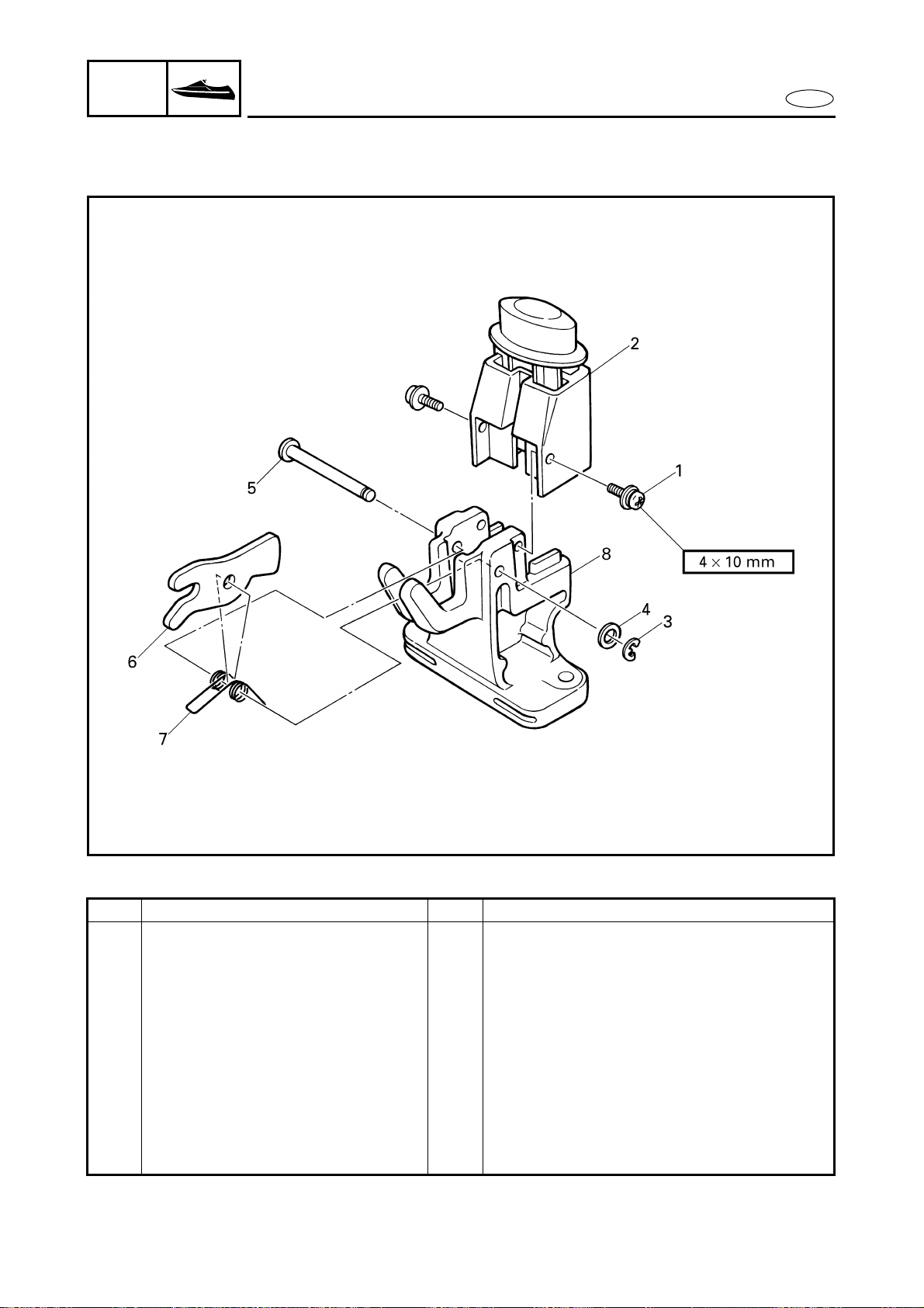
8-30
E
HULL
HOOD
BUZZER AND HOOD LOCK
EXPLODED DIAGRAM
REMOVAL AND INSTALLATION CHART
Step Procedure/Part name Q’ty Service points
HOOD LOCK DISASSEMBLY Follow the left “Step” for disassembly.
1 Screw 2
2 Hood lock button assembly 1
3 Circlip 1
4 Washer 1
5 Pin 1
6 Hook lever 1
7 Spring 1
8 Hood lock body 1
Reverse the disassembly steps for
assembly.
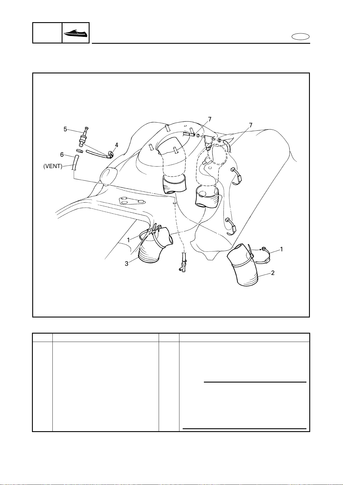
8-31
E
HULL
HOOD
HOSES
HOSES
EXPLODED DIAGRAM
REMOVAL AND INSTALLATION CHART
Step Procedure/Part name Q’ty Service points
HOSES REMOVAL Follow the left “Step” for removal.
Engine unit Refer to “ENGINE UNIT” in chapter 5.
Steering console cover assembly Refer to “STEERING CONSOLE COVER”.
1 Band 2
2 Ventilation hose (stern side) 1
NOTE:
● Route the ventilation hose (bow side) in
front of the fuel level sensor lead.
● Route the ventilation hose (stern side)
front the oil level sensor lead and the oil
tank breather hose.
3 Ventilation hose (bow side) 1
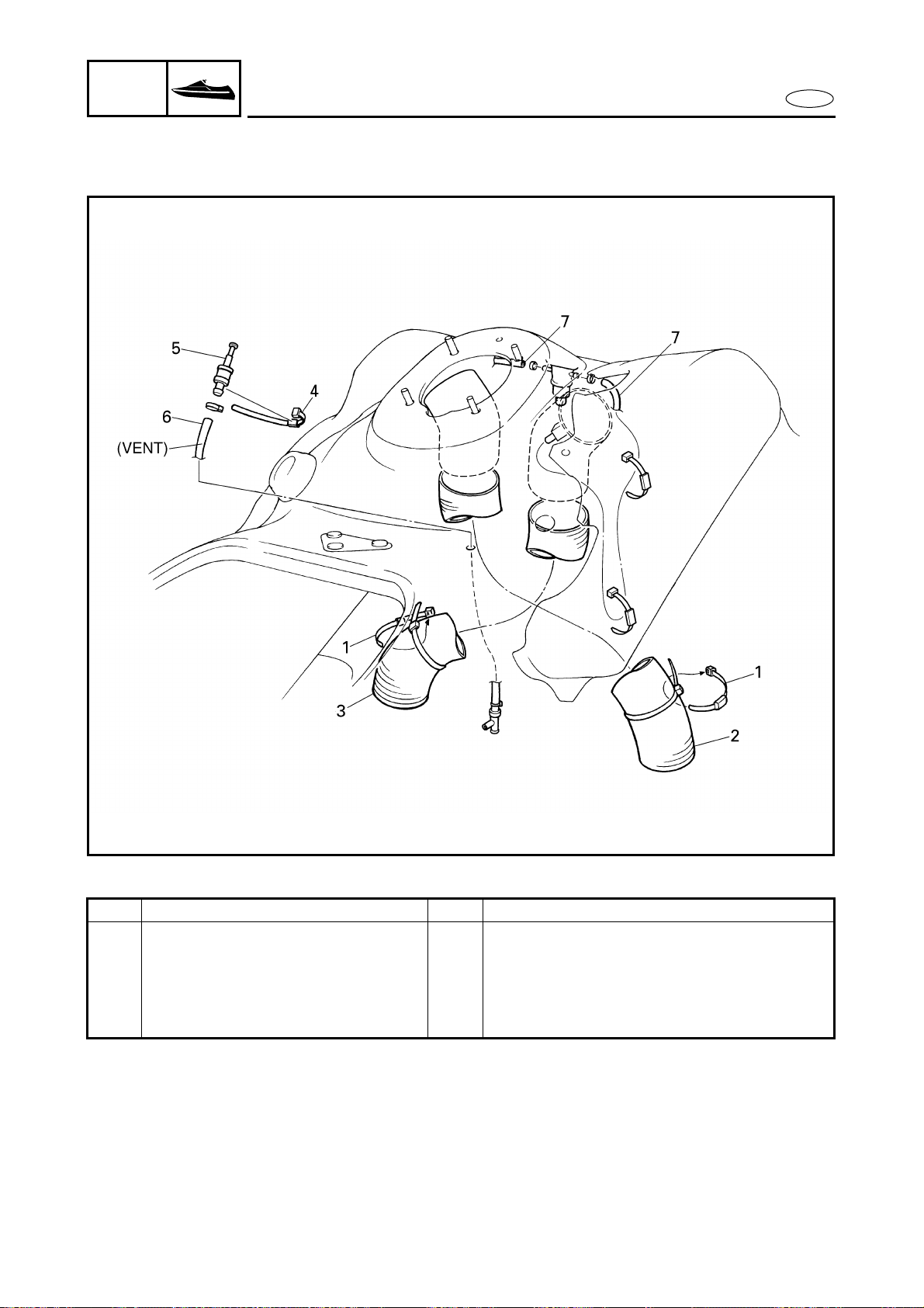
8-32
E
HULL
HOOD
HOSES
EXPLODED DIAGRAM
Step Procedure/Part name Q’ty Service points
4 Band 1
5 Check valve 1
6 Oil tank breather hose 1
7 Fuel tank breather hose 2
Reverse the removal steps for installation.
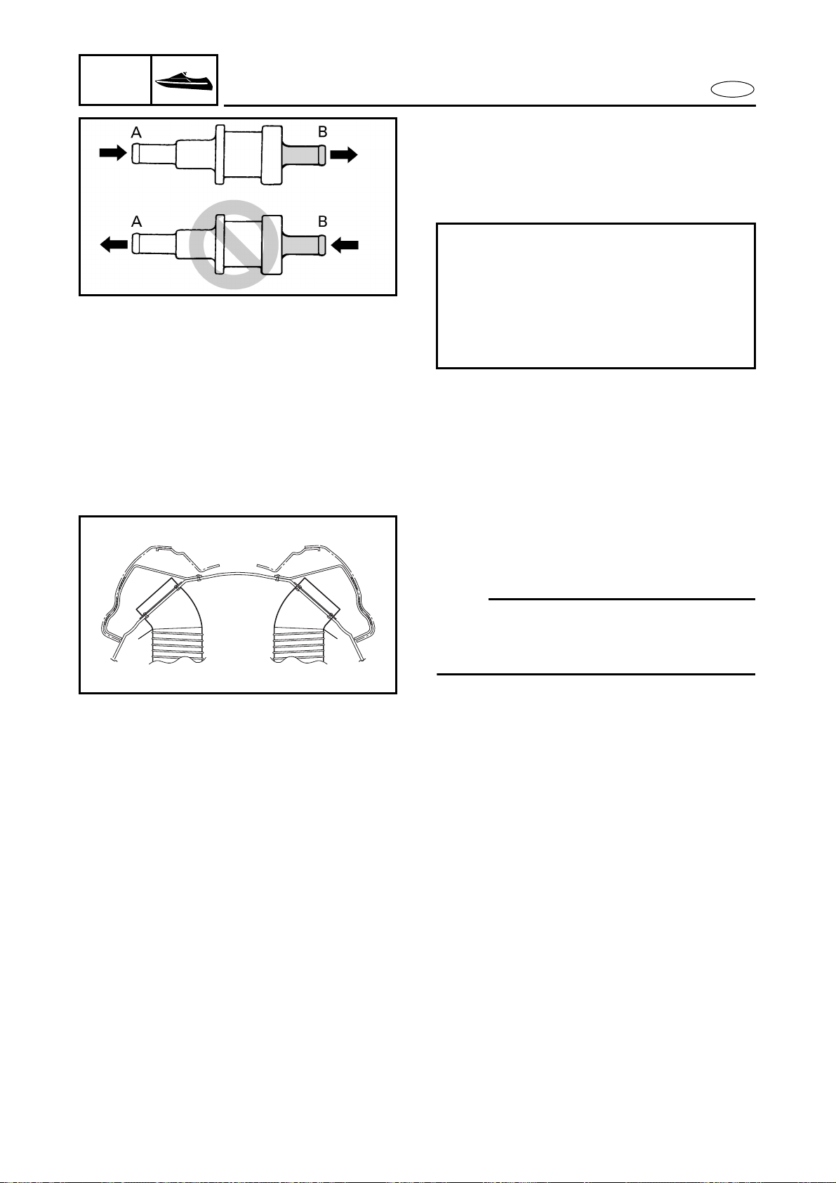
8-33
E
HULL
HOOD
HOSES
SERVICE POINTS
Check valve inspection
1. Check:
● Check valve
Faulty → Replace.
Checking steps:
● Connect a hose to the end of check
valve “A” and blow into it.
Air should come out from end “B”.
● Connect the hose to the end of check
valve “B” and blow into it.
Air should not come out from end “A”.
Ventilation hose installation
1. Install:
● Ventilation hose
NOTE:
Insert the ventilation hose into the ventila-
tion fitting until it reaches the bend a in the
fitting.
a
a
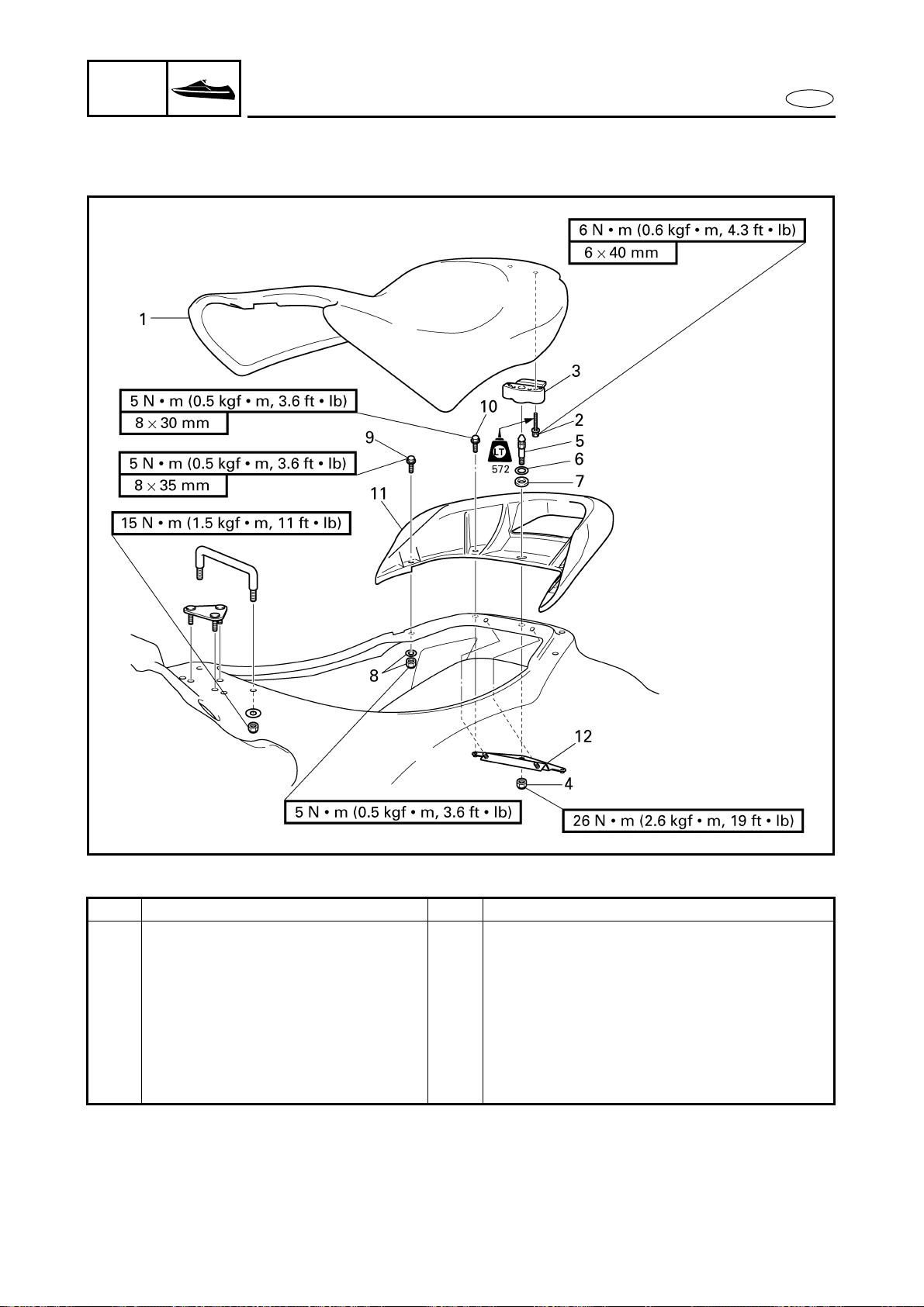
8-34
E
HULL
HOOD
SEATS AND HAND GRIP
SEATS AND HAND GRIP
EXPLODED DIAGRAM
REMOVAL AND INSTALLATION CHART
Step Procedure/Part name Q’ty Service points
SEATS AND HAND GRIP
REMOVAL
Follow the left “Step” for removal.
1 Seat assembly 1
2 Bolt 2
3 Seat lock assembly 1
4 Nut 1
5 Notch 1
6 Washer 1

8-35
E
HULL
HOOD
SEATS AND HAND GRIP
EXPLODED DIAGRAM
Step Procedure/Part name Q’ty Service points
7 Rubber ring 1
8 Nut/washer 2/2
9 Bolt 2
10 Bolt 2
11 Hand grip 1
12 Bracket 1
Reverse the removal steps for installation.

8-36
E
HULL
HOOD
SEATS AND HAND GRIP
SERVICE POINTS
Seat lock inspection
1. Inspect:
● Seat lock
Damage/wear → Replace.
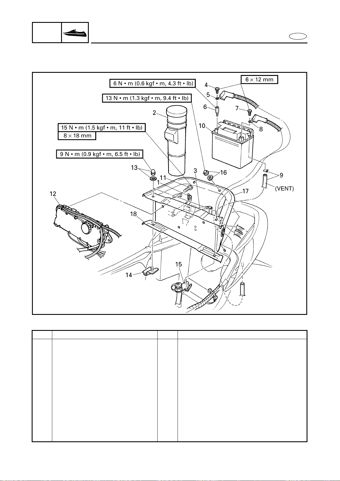
8-37
E
HULL
HOOD
BATTERY BOX
BATTERY BOX
EXPLODED DIAGRAM
REMOVAL AND INSTALLATION CHART
Step Procedure/Part name Q’ty Service points
BATTERY BOX REMOVAL Follow the left “Step” for removal.
1 Band 1
2 Fire extinguisher container 1
3 Band 1
4 Bolt 1
5 Battery negative lead 1
6 Terminal extension 1
7 Bolt 1
8 Battery positive lead 1
9 Clip/breather hose 1/1
10 Battery 1
11 Bolt 3
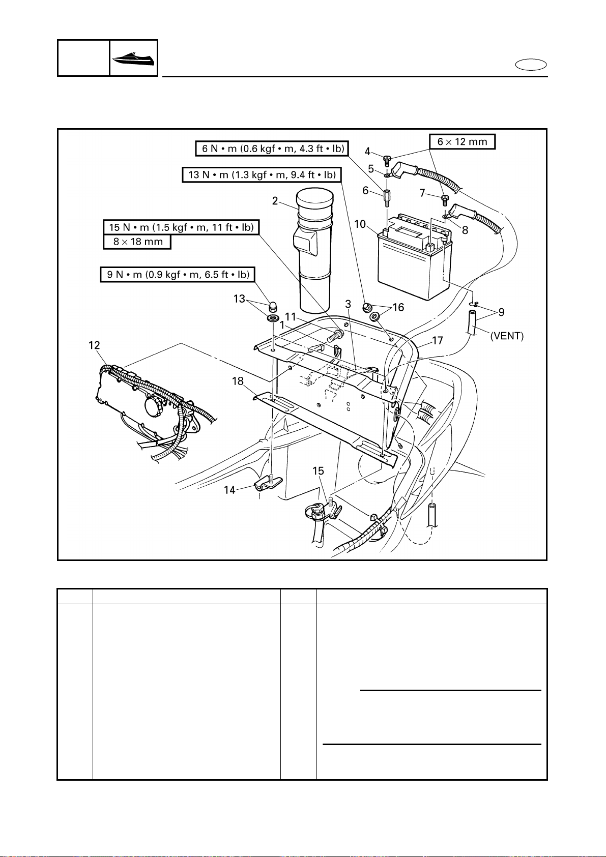
8-38
E
HULL
HOOD
BATTERY BOX
EXPLODED DIAGRAM
Step Procedure/Part name Q’ty Service points
12 Electrical box 1
13 Cap nut/washer 2/2
14 Holder 1
15 Holder 1
16 Cap nut/washer 2/2
17 Battery box 1
NOTE:
Before installing the battery box, route
the battery leads and battery breather
hose through the holes of the battery box.
18 Stay 1
Reverse the removal steps for installation.
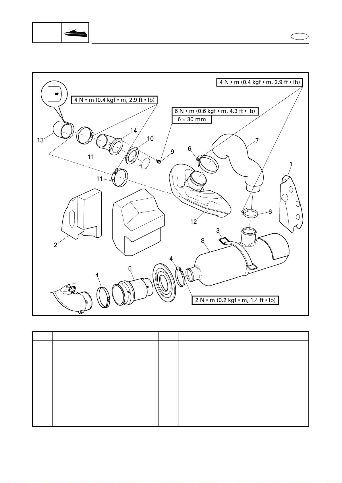
8-39
E
HULL
HOOD
EXHAUST SYSTEM
EXHAUST SYSTEM
EXPLODED DIAGRAM
REMOVAL AND INSTALLATION CHART
Step Procedure/Part name Q’ty Service points
EXHAUST SYSTEM REMOVAL Follow the left “Step” for removal.
Battery box Refer to “BATTERY BOX”.
Jet pump unit assembly Refer to “JET PUMP UNIT” in chapter 6.
1 Floatation 1
2 Floatation 1
3 Water lock band 1
4 Hose clamp 2
5 Rubber joint 1
6 Hose clamp 2
7 Rubber hose 1
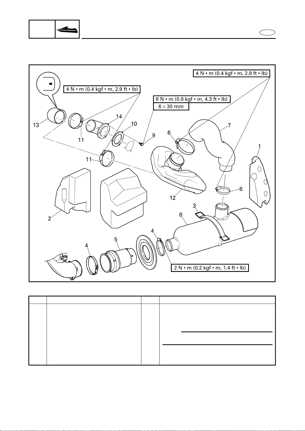
8-40
E
HULL
HOOD
EXHAUST SYSTEM
EXPLODED DIAGRAM
Step Procedure/Part name Q’ty Service points
8 Water lock 1
9 Bolt 3
10 Packing 1
11 Hose clamp 2
NOTE:
Remove parts 11 to 14 as a set.
12 Water tank 1
13 Rubber hose 1
14 Exhaust outlet 1
Reverse the removal steps for installation.
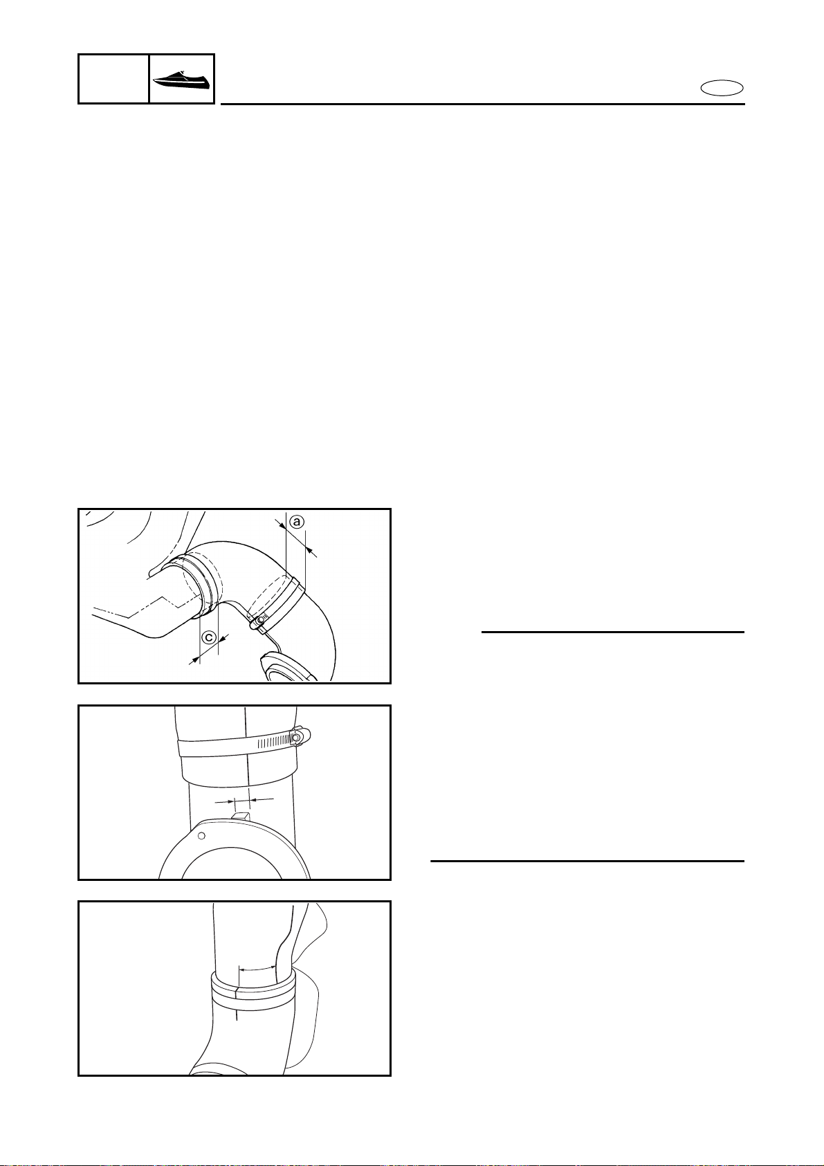
8-41
E
HULL
HOOD
EXHAUST SYSTEM
SERVICE POINTS
Exhaust system inspection
1. Inspect:
● Water lock band
Cracks/damage → Replace.
2. Inspect:
● Rubber hoses
Burns/cracks/damage → Replace.
3. Inspect:
● Water lock
Cracks/leaks → Replace.
4. Inspect:
● Water tank
Cracks/damage/leaks → Replace.
Exhaust component parts sub-assembly
1. Install:
● Exhaust outlet
● Rubber hose
● Water tank
NOTE:
● Insert the exhaust outlet 45 mm (1.8 in) a
into the rubber hose.
● Make sure that there is a surface distance
of 10 mm (0.4 in) b between the parting
lines of the exhaust outlet and the rubber
hose.
● Insert the water tank 45 mm (1.8 in) c into
the rubber hose.
● Make sure that there is a surface distance
of 45 mm (1.8 in) d between the parting
lines of the water tank and rubber hose.
b
d
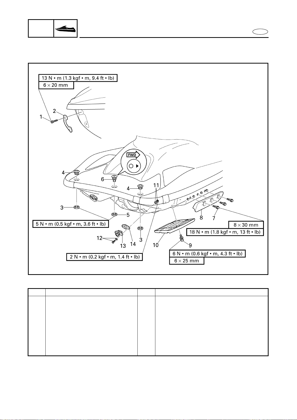
8-42
E
HULL
HOOD
DECK AND HULL
DECK AND HULL
EXPLODED DIAGRAM
REMOVAL AND INSTALLATION CHART
Step Procedure/Part name Q’ty Service points
DECK AND HULL DISASSEMBLY Follow the left “Step” for disassembly.
1 Bolt 2
2 Bow eye 1
3 Nut 2
4 Rope hole fitting 2
5 Nut 1
6 Spout 1
7 Bolt 6
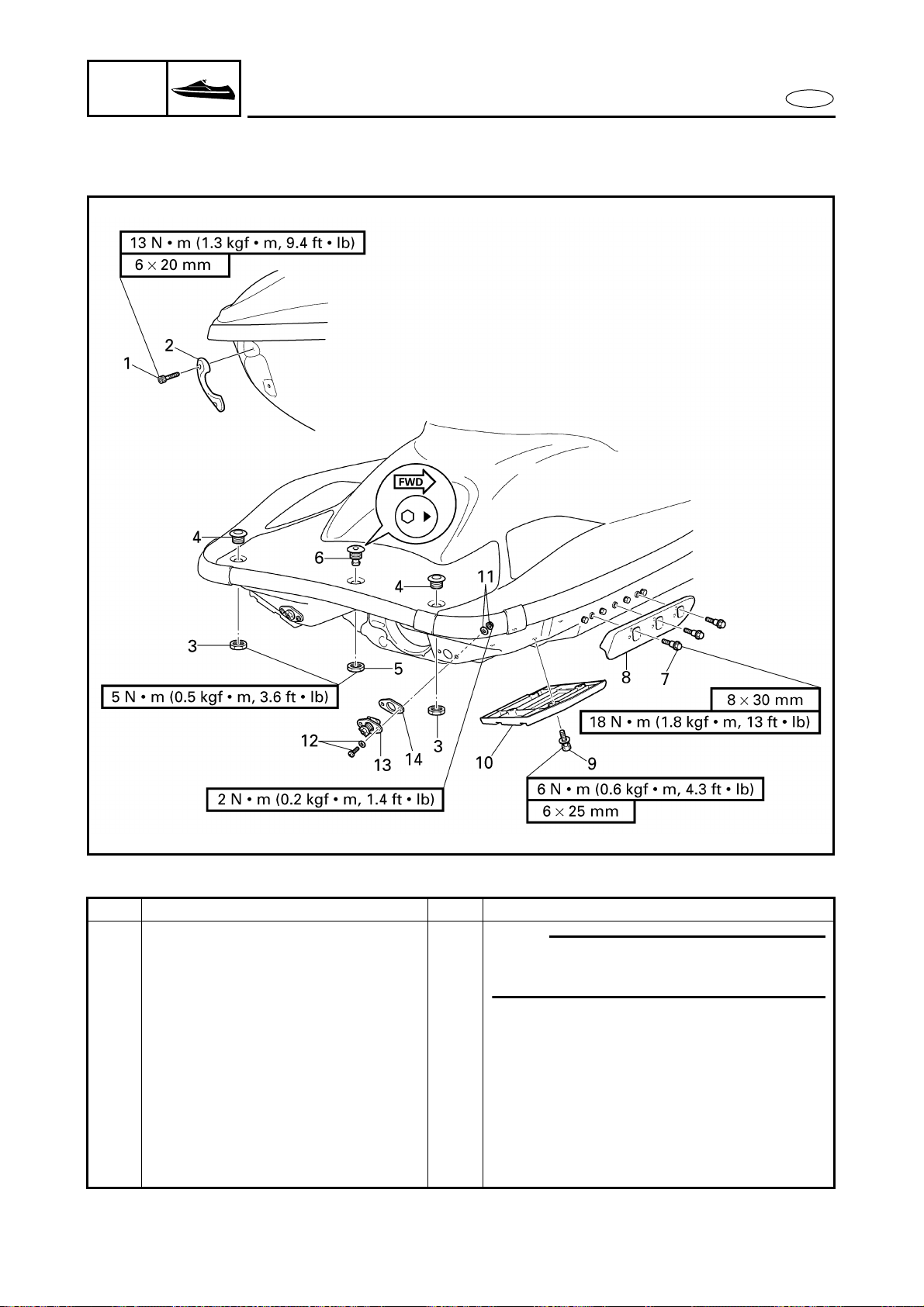
8-43
E
HULL
HOOD
DECK AND HULL
EXPLODED DIAGRAM
Step Procedure/Part name Q’ty Service points
8 Sponson 2
NOTE:
Make sure install the starboard and port
side sponsons to the same position.
9 Bolt 8
10 Flap 2
11 Nut/washer 4/4
12 Screw/washer 4/4
13 Drain plug 2
14 Packing 2
Reverse the disassembly steps for
assembly.
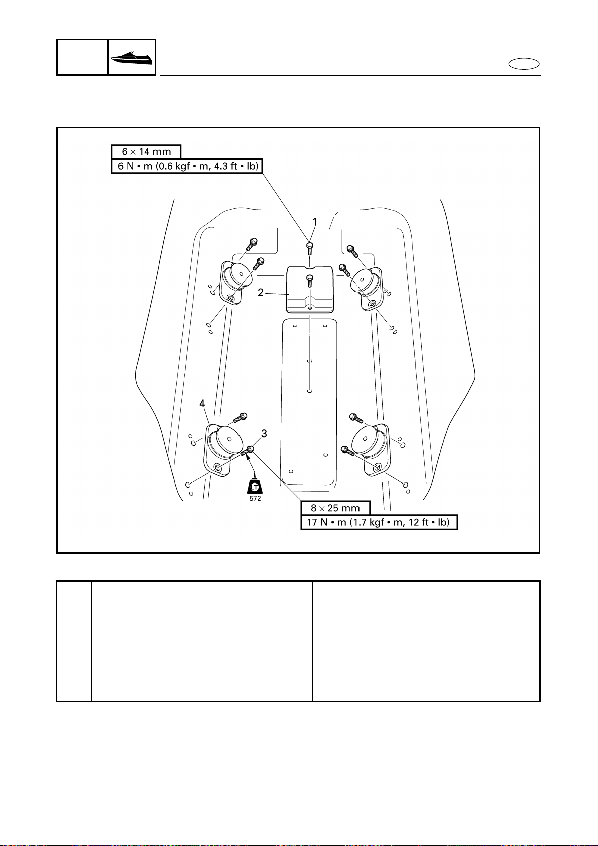
8-44
E
HULL
HOOD
ENGINE MOUNT
ENGINE MOUNT
EXPLODED DIAGRAM
REMOVAL AND INSTALLATION CHART
Step Procedure/Part name Q’ty Service points
ENGINE MOUNT REMOVAL Follow the left “Step” for removal.
Engine unit Refer to “ENGINE UNIT” in chapter 5.
1 Bolt 2
2 Damper 1
3 Bolt 8
4 Engine mount 4
Reverse the removal steps for installation.
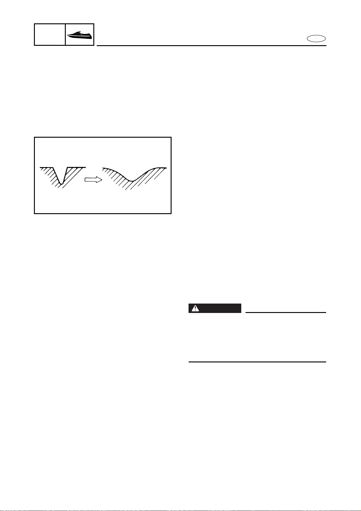
8-45
E
HULL
HOOD
ENGINE MOUNT
HULL REPAIR
Shallow scratches
1. Sand the scratches with 400 grit sand-
paper (either wet or dry) until the
scratches are smooth. Then, sand the
scratches once again with 600 grit sand-
paper (either wet or dry).
Deep scratches
1. Remove any sharp or rough edges from
the hull surface.
2. Sand the scratches and a 1-inch circum-
ference around them with 80 grit sand-
paper (either wet or dry).
3. Clean the entire area with acetone and
let it completely dry.
4. Mix gel-coat and gel-coat thickener to
form a putty, and then add the catalyst
to the putty.
5. Apply the putty, spread it with a squee-
gee, and then cover the putty with wax
paper.
6. When the putty has set, sand it. Smooth
the area with 80–400 grit sandpaper
(either wet or dry) and a sanding block.
7. Clean the area with a dry cloth and then
polish it.
WARNING
Resins, catalysts, and solvents are flamma-
ble and toxic; only use them in a well-venti-
lated area and keep them away from open
flames and sparks. Always follow the man-
ufacturer’s instructions and warnings.
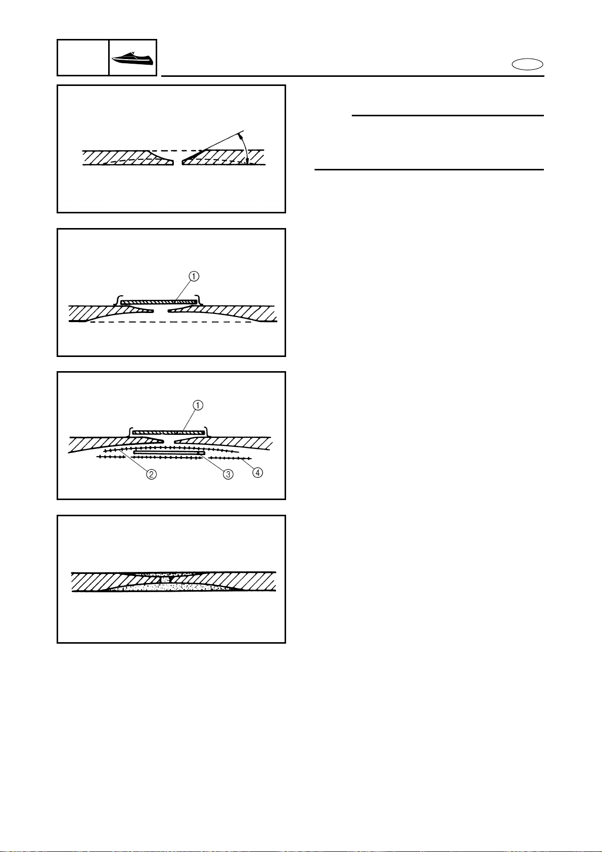
8-46
E
HULL
HOOD
ENGINE MOUNT
Cracks and punctures
NOTE:
Before attempting to repair any cracks or
punctures, refer to “WATERCRAFT FRP
REPAIR MANUAL”.
1. Remove any damaged fiberglass.
2. Cut the damaged area and separate it
approximately 0.25 inch.
3. On the outside of the hull, grind the
separated edge of the area to less than
5˚ as shown.
4. Working from inside the hull, grind the
damaged area approximately 4 inches
beyond the damage.
5. Clean the area with acetone, apply BP-1
or an equivalent primer onto both sides
of the damaged area, and then allow it
to cure for approximately 30 minutes.
6. Cover a piece of cardboard with wax
paper 1 and then cover the damaged
area with it.
7. Combine the polyester resin and the
catalyst, and then apply the mixture
onto the hull.
8. Install a glass mat 2 (2 inches smaller
than the ground area).
9. Apply the resin.
10. Install a 20 oz. fiberglass cloth 3 (1 inch
smaller than the glass mat).
11. Apply the resin.
12. Install another glass mat 4 (1 inch
smaller than the ground area).
13. When the resin has hardened remove
the piece of cardboard.
14. Finish the outer surface.
Refer to steps (3)–(7) in the “Deep
scratches” section.
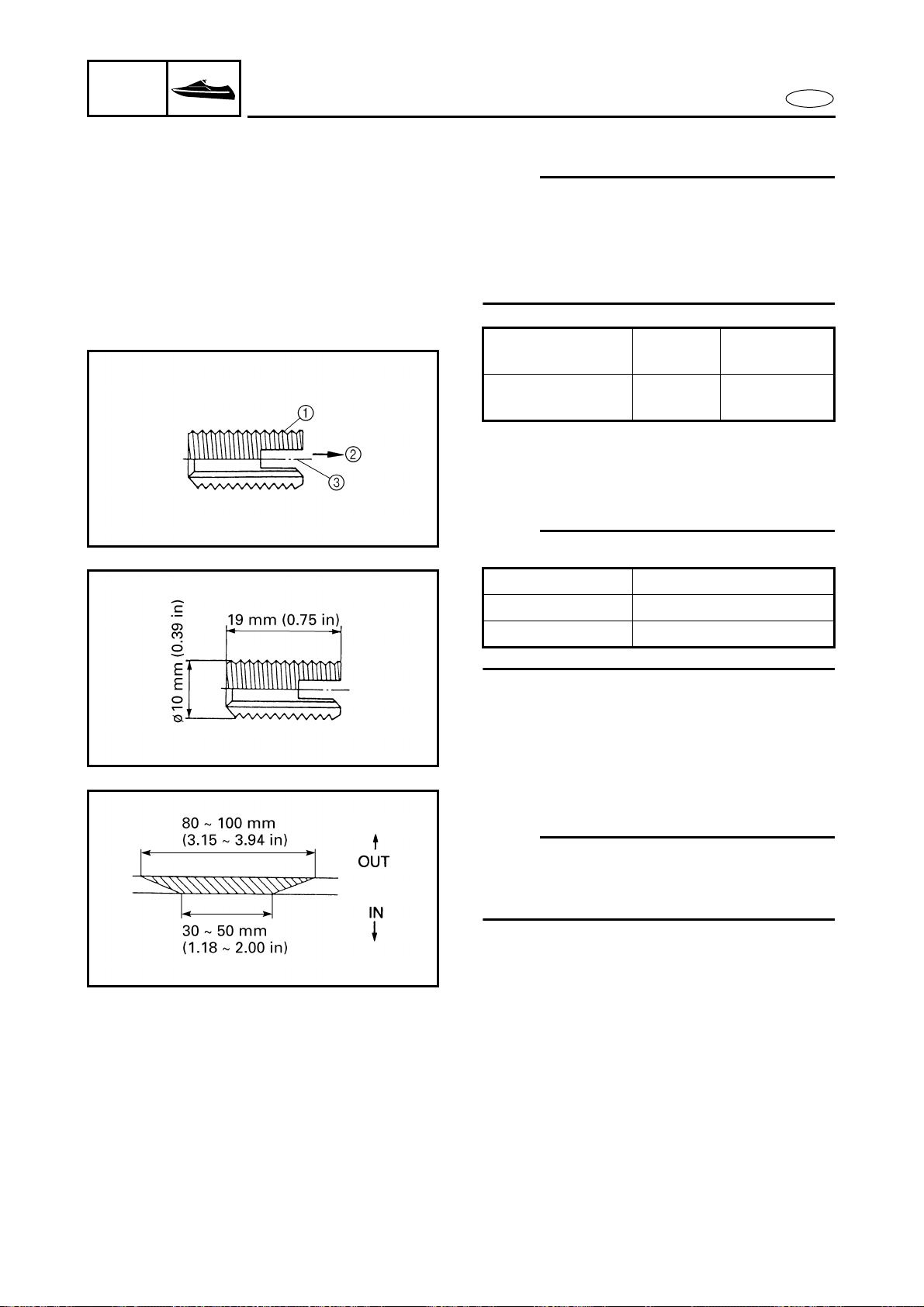
8-47
E
HULL
HOOD
ENGINE MOUNT
Insert nut
NOTE:
Use the insert nut when:
● A pop nut which was attached to the hull
slipped off or,
● When a bolt which was fastened to an
insert nut or pop nut broke.
● Nut 1
● Thread direction 2
● Slot to be threaded 3
NOTE:
Drilling size
Part No.
Part
name
Remarks
EW2-62733-09 Nut
Stainless
steel, M6
Material Pilot hole diameter
FRP or SMC 9.1–9.2 mm (0.36 in)
Brass 9.4 mm (0.37 in)
Example 1:
NOTE:
Before attempting to install the insert nut,
refer to “WATERCRAFT FRP REPAIR MAN-
UAL”.
The insert nut is used to repair the pop nut
designed for the ride plate.
(By repairing the FRP portion, the insert nut
can be used for all models.)
1. Remove:
● Pop nut
2. Clean the surface to be scarfed and the
inside of the hull with acetone.
3. Scarf the shaded portion of the hull.
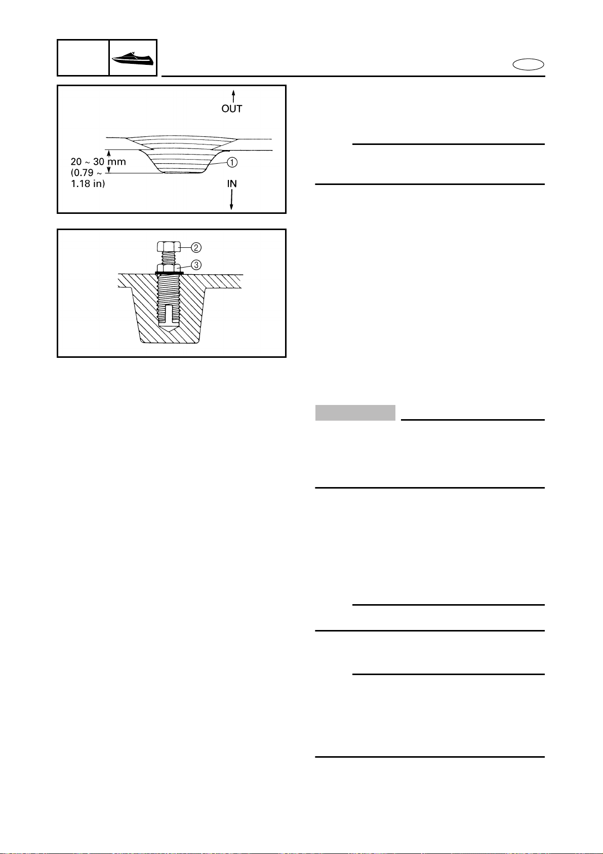
8-48
E
HULL
HOOD
ENGINE MOUNT
4. First, apply tape 1 to the inner surface
of the hull and then laminate fiberglass
mats over the tape with resin.
NOTE:
When it is possible to work inside the hull,
laminate the mats from the inside.
5. Sand the outer surface of the hull until it
is smooth.
6. Install the ride plate.
7. Drill a 20 mm (0.79 in) deep hole in the
center of the laminated fiberglass layers
with a 9.2 mm (0.36 in) diameter drill
bit.
8. Pass the bolt 2 through the insert nut
and lock the bolt with the nut 3 as
shown.
9. Screw in the insert nut so that the top is
flush with the FRP surface.
10. Loosen the locknut and remove the
bolt.
CAUTION:
● Only use a steel bolt with a tensile
strength of 8T or more.
● If the bolt is inferior in strength or is
made of stainless steel it may break.
● Bolt 2
● Locknut 3
Example 2:
The brass insert nut, which is designed for
the Super Jet ride plate or the intake screen,
is used as follows.
NOTE:
If the bolt is broken, drill it out.
1. Drill a hole in the hull.
NOTE:
● First, use a small-diameter drill bit fol-
lowed by drill bits of gradually increasing
diameter.
● Use a 9.4 mm (0.37 in) drill bit for the final
drilling.
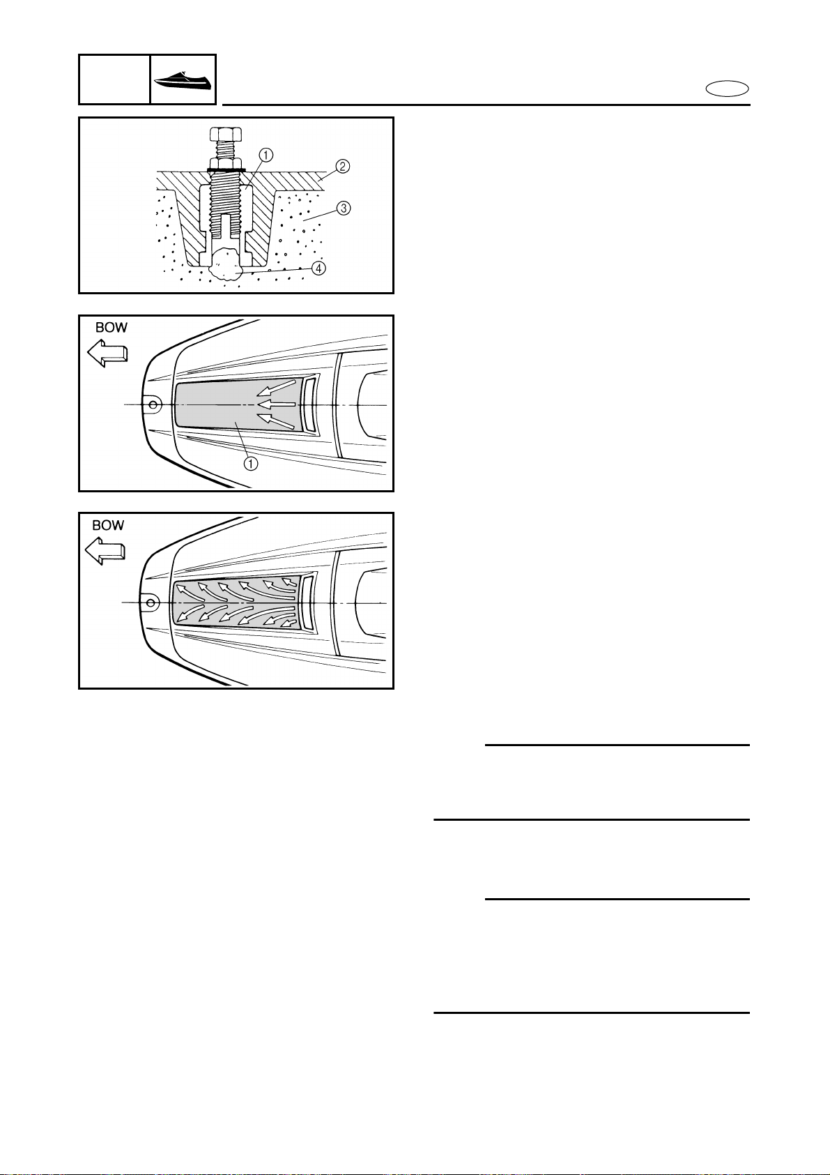
8-49
E
HULL
HOOD
ENGINE MOUNT
2. To prevent water from entering the ure-
thane foam, apply silicone sealant to
the inside of the hole as shown.
3. Install the insert nut as explained in
“Example 1”.
● Brass insert nut 1
● Hull 2
● Urethane foam 3
● Silicone sealant 4
Graphic removal
1. Hold a hair dryer approximately 1.5
inches above the graphic 1.
2. Apply heat to one corner of the graphic.
3. Slowly peel off the heated portion of the
graphic and continue working until you
reach the opposite corner and the entire
graphic is removed.
4. After the graphic is removed, clean the
entire bow area with isopropyl alcohol
to remove any residual adhesive.
Graphic installation
1. Mix 1 tablespoon of liquid detergent
and water in a 1-quart spray bottle.
2. Remove the backing from the new
graphic.
3. Spray the soap and water mixture onto
both sides of the graphic, and also onto
the hull area where the graphic will be
installed.
NOTE:
Spraying the front of the graphic with the
soap and water mixture will protect it from
being scratched during installation.
4. Align the graphic onto the fitting area of
the hull and position it with a squeegee.
NOTE:
Be sure to remove any air bubbles from the
graphic with the squeegee. Work from the
top of the graphic down and slide the
squeegee outwards from the graphic’s cen-
ter line.
5. Allow the graphic to dry before waxing
or using the watercraft.

9-1
TRBL
ANLS
E
TROUBLE ANALYSIS
TROUBLE ANALYSIS
NOTE:
The following items should be checked before the “Trouble analysis” chart is consulted.
1. The battery is charged and its specified gravity is within specification.
2. There are no incorrect wiring connections.
3. Wiring connections are properly secured and not rusty.
4. The lock plate is attached to the engine stop lanyard switch.
5. Fuel is reaching the carburetors.
TROUBLE ANALYSIS CHART
Problems Items to be checked
ENGINE WILL NOT START
ROUGH IDLING
ENGINE STALLS
ENGINE WILL NOT STOP
POOR PERFORMANCE
OVERHEATING
LOOSE STEERING
BILGE INCREASE
IRREGULAR WARNING INDICATION
POOR BATTERY CHARGING
YPVS SERVOMOTOR DOES NOT MOVE
Items
Reference
chapter
FUEL SYSTEM
Fuel tank 4
Fuel tank breather hose 4
Fuel hose 4
Fuel filter 4
Fuel pump 4
Carburetors 4
Carburetor synchronization 4
Trolling speed 3
POWER UNIT
Spark plug(s) 3
Compression 5
Reed valves 5
Cylinder head gasket 5
Piston rings 5
Cylinder block 5
Seals 5
Crankcase 5
Pistons 5
Bearings 5
Bearing housing 5
Drive couplings 5
Rubber coupling 5
9-2
TRBL
ANLS
E
TROUBLE ANALYSIS
Pilot water hose 5
Water hose 5
Water passage 5
JET PUMP UNIT
Duct 6
Impeller 6
Intake grate 6
Bearings 6
Intake duct 6
Water inlet hose 6
Bilge hose 6
Bilge strainer 6
Bilge hose joint 6
Valve body 6
ELECTRICAL
CDI unit 7
Lighting coil 7
Charge coil 7
Pickup coil (Pulser coil) 7
Ignition coil 7
Rectifier/regulator 7
Electrical sensor(s) 7
Starter relay, starter motor 7
YPVS unit 7
Battery 3
Fuse(s) 7
Wire harness, electrical coupler(s) 7
HULL AND HOOD
Steering column 8
Water lock 8
Exhaust hose 8
Muffler 8
Drain plugs 8
Problems Items to be checked
ENGINE WILL NOT START
ROUGH IDLING
ENGINE STALLS
ENGINE WILL NOT STOP
POOR PERFORMANCE
OVERHEATING
LOOSE STEERING
BILGE INCREASE
IRREGULAR WARNING INDICATION
POOR BATTERY CHARGING
YPVS SERVOMOTOR DOES NOT MOVE
Items
Reference
chapter


YAMAHA MOTOR CORPORATION, USA
Printed in USA
Nov. 2000 — ?.? × 1 CR
F0W-28197-1A-11
(GP800A)
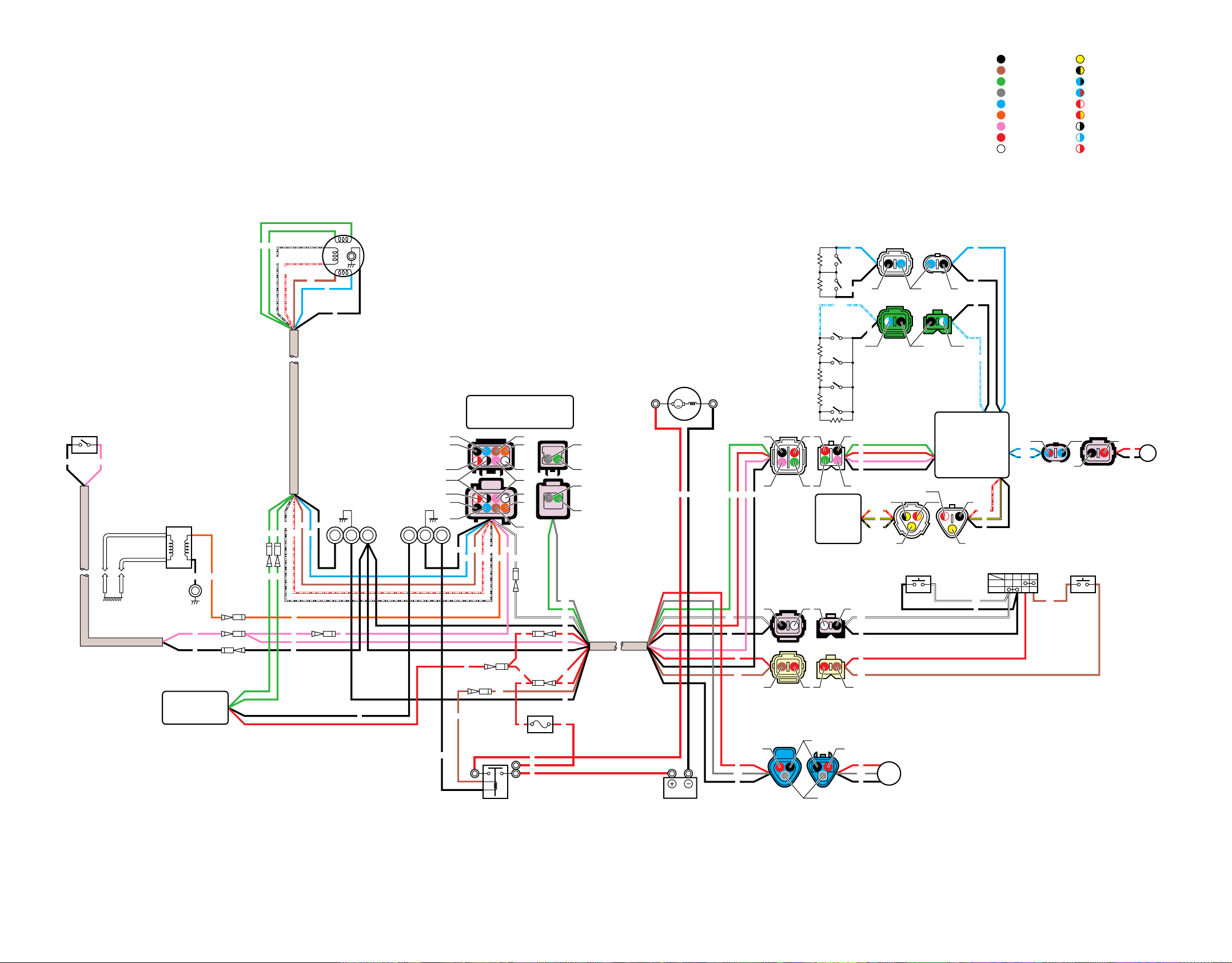
M
WIRING DIAGRAM
GP800R
Y
B/Y
L/B
L/R
R/W
R/Y
W/B
W/L
W/R
:
:
:
:
:
:
:
:
:
Yellow
Black/yellow
Blue/black
Blue/red
Red/white
Red/yellow
White/black
White/blue
White/red
COLOR CODE
1 Thermoswitch
2 Ignition coil
3 Lighting coil
4 Pickup
coil
5 Charge coil
6 CDI unit
7 Starter motor
G Engine stop switch
H Engine stop
lanyard switch
I Start switch
A Battery
0 Fuse (10A)
9 Starter relay
8 Rectifier/
regulator
B YPVS servomotor
C Oil level sensor
D Fuel level sensor
E Multifunction
meter
F Speed
sensor
J Buzzer
B
B
B
P
P
O G G
G
G
Br
G
L
B
G
O
B
P P
P
W/B
W/R
Br
Br
Br
Br
L
B
B
B
R
R B
R
B
B
B
W
W
Gy
P
R
B
B
B
B
B
B
B
L L
Gy
R
R
Br
Br
R
B
BBWW
W
W
B
Y
B
R
R
P
P
B
Gy
R
RR
R
R
R
R
R
R
R
G
G
G
W/B
W/R
Br
L W
PB
O
W/B
R/Y
B/Y
Y
R
B
R/W
L/B
L/R
W/L
W/L
W/R
W/R
W/R
W/B
B
B
Br
Br
O
O
P
W G
G
Gy
Gy
W
L
L
Gy
B
RR
Br R
PP
B
GG
R
R B
B/Y B
R/W
R/Y
W/LW/L
L/RR
B
L/B
B
B
BL
Y Y
WB RBr
BrR
SET
PULL
B
B
Br
G
Gy
L
O
P
R
W
:
:
:
:
:
:
:
:
:
Black
Brown
Green
Gray
Blue
Orange
Pink
Red
White

