Loading ...
Loading ...
Loading ...
2-10
SPEC
E
TIGHTENING TORQUES
Hand grip – deck Nut M8 2 5 0.5 3.6
Seat bracket – deck Nut M8 2 15 1.5 11
Battery box/stay – holder Nut M6 2 9 0.9 6.5
Battery box – bracket/deck Nut M8 2 13 1.3 9.4
Battery box – electrical box Bolt M8 3 15 1.5 11
Extension bolt – battery negative
terminal
Bolt M6 1 6 0.6 4.3
Exhaust outlet – hull Bolt M6 3 6 0.6 4.3
Sponson – hull Bolt M8 6 18 1.8 13
Spout – hull Nut M24 1 5 0.5 3.6
Rope hole – hull Nut M24 2 5 0.5 3.6
Bow eye – hull Bolt M6 2 13 1.3 9.4
Flap – hull Bolt M6 8 6 0.6 4.3
Drain plug/packing – hull Nut M5 4 2 0.2 1.4
Engine mount – hull Bolt M8 8 17 1.7 12
572
LT
Engine damper – hull Bolt M6 2 6 0.6 4.3
Part to tightened Part name
Thread
size
Q’ty
Tightening torque
Remarks
N•m kgf•m ft•lb
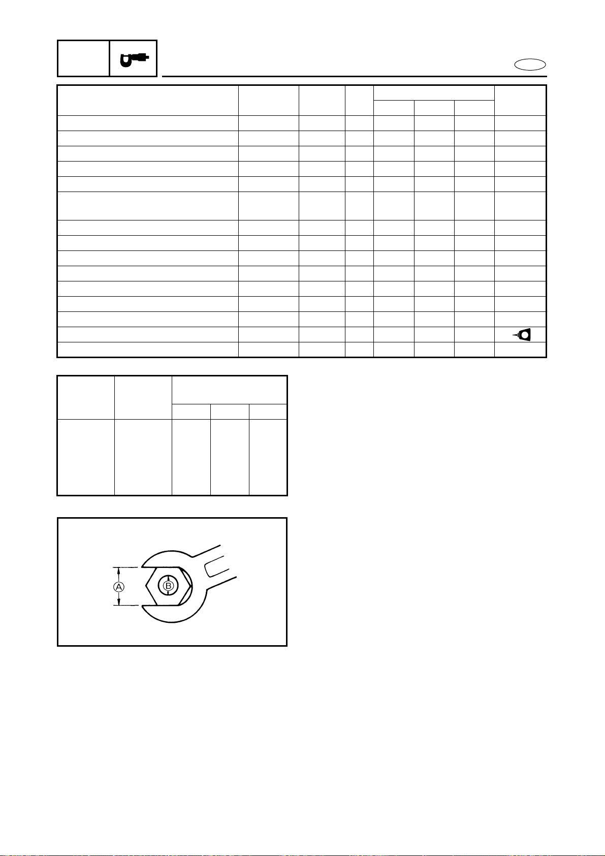
GENERAL TORQUE
This chart specifies tightening torques for
standard fasteners with a standard ISO
thread pitch. Tightening torque specifica-
tions for special components or assemblies
are provided in applicable sections of this
manual. To avoid warpage, tighten multi-
fastener assemblies in a crisscross fashion
and progressive stages until the specified
tightening torque is reached. Unless other-
wise specified, tightening torque specifica-
tions require clean, dry threads.
Components should be at room tempera-
ture.
Nut A Bolt B
General torque
specifications
N•m kgf•m ft•lb
8 mm M5 5.0 0.5 3.6
10 mm M6 8.0 0.8 5.8
12 mm M8 18 1.8 13
14 mm M10 36 3.6 25
17 mm M12 43 4.3 31
Loading ...
Loading ...
Loading ...