Loading ...
Loading ...
Loading ...
5-39
POWR
E
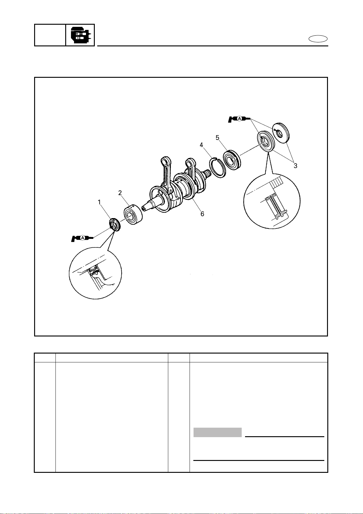
CRANKSHAFT
CRANKSHAFT
EXPLODED DIAGRAM
REMOVAL AND INSTALLATION CHART
Step Procedure/Part name Q’ty Service points
CRANKSHAFT REMOVAL Follow the left “Step” for removal.
Crankcase Refer to “CRANKCASE”.
1 Oil seal 1
2 Bearing 1
3 Oil seal 2
4 Bearing clip 1
5 Bearing 1
6 Crankshaft 1
CAUTION:
Install the bearing locating pins into the
grooves in the crankcase body.
Reverse the removal steps for installation.
Loading ...
Loading ...
Loading ...