Loading ...
Loading ...
Loading ...
7-36
E
–+
ELEC
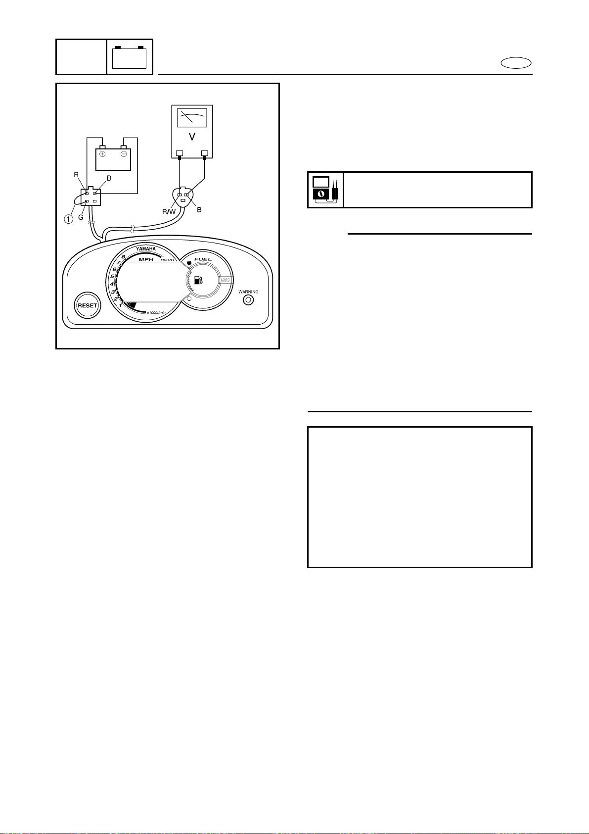
INDICATION SYSTEM
Speed meter
1. Check:
● Speed meter output voltage
Within specification → Check the speed
sensor output voltage and pulses.
Out of specification → Replace.
NOTE:
● When inspecting the multifunction meter
unit or emptying the fuel tank, connect the
white/blue and black terminals (green
two-pin connector) with a jumper lead 1
to prevent the fuel warning indicator from
being activated.
● When inspecting the multifunction meter
unit or emptying the oil tank, connect the
blue and black terminals (white two-pin
connector) with a jumper lead 2 to pre-
vent the oil warning indicator from being
activated.
Speed meter output voltage:
10.5 V
Checking steps:
● Supply DC 12 voltage to the white
four-pin connector (+: red, –: black)
with a battery.
● Connect the green and red terminals
with a jumper lead 1.
● Measure the voltage on the speed sen-
sor connector (white three-pin connec-
tor) between the red/white and black
leads.
Loading ...
Loading ...
Loading ...