Loading ...
Loading ...
Loading ...
Front/Back Panel Diagrams & Descriptions Front Panel
1
1. Front/Back Panel Diagrams & Descriptions
Front Panel
Note: For detailed operating instructions, please refer to the User’s Manual on the included CD
or found on the product listing online: http://amcrest.com/ip-security-camera-systems.html/
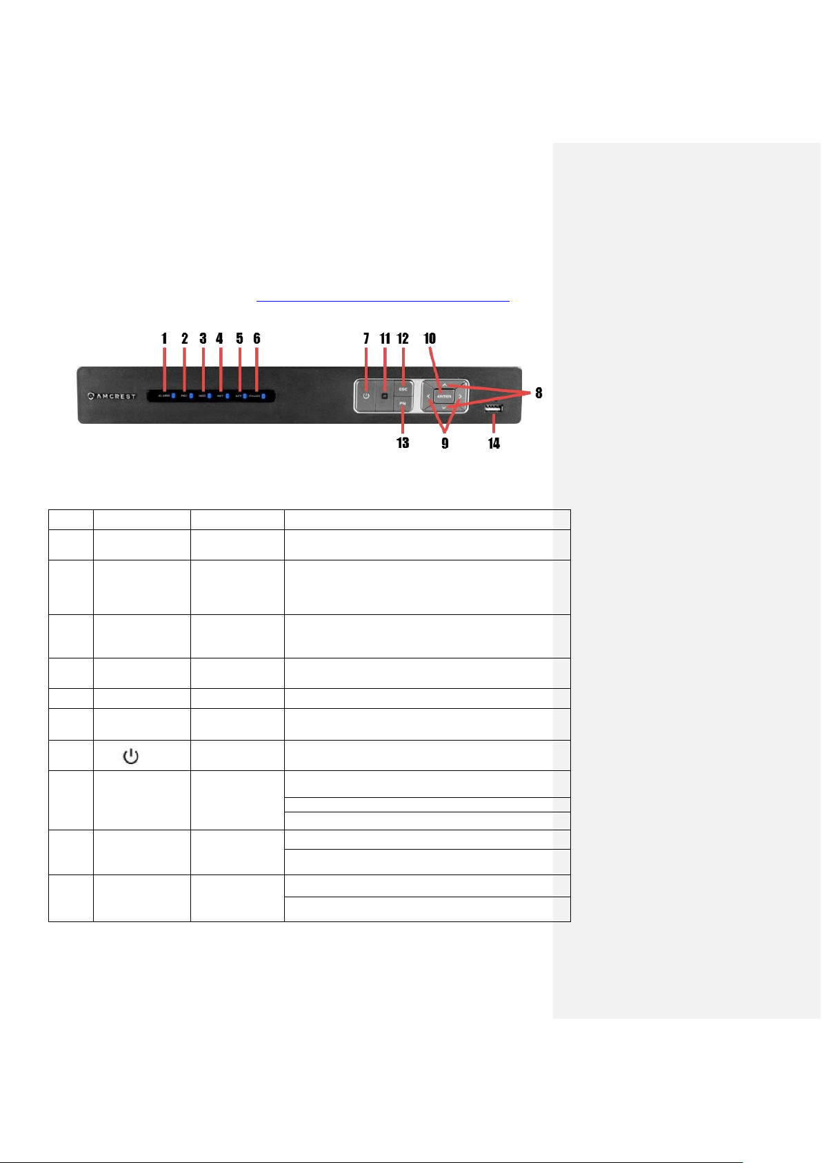
The front panel is shown in Figure 1.
Figure 1
Please refer to the following chart for information on the front panel buttons
#
Icon
Name
Function(s)
1
ALARM
Alarm status
indicator light
When an alarm event occurs, this LED becomes
blue to alert you.
2
REC
Recording status
indicator light
When the NVR is recording footage to the hard
drive, this LED will become blue to alert you.
3
HDD
HDD status
indicator light
When an HDD error occurs or the HDD capacity is
below the specified threshold, this LED becomes blue
to alert you.
4
NET
Network status
indicator light
When a network error occurs or there is no network
connection, this LED becomes blue to alert you.
5
ACT
ENTER
Confirms the current operation.
6
POWER
Power status
indicator light
When the NVR is powered on, this LED will remain
blue.
7
Power button
Press and hold the power button for 3 seconds to boot
up or shut down the NVR.
8
🔺 / 🔻
Up/Down
Activates current controls, modifies settings, and
allows navigating up and down through options.
Increases/Decreases numerals.
Assists in functions such as PTZ menu.
9
< / >
Left/Right
Shifts current activated controls.
When in playback, use these buttons to control the
playback bar.
10
ENTER
Enter
Confirms the current operation.
Goes to the default button.
Loading ...
Loading ...
Loading ...