
NVR Quick Start Guide
Version 4.0.4
Revised May 18th, 2016

Table of Contents
Check Packaging ................................................................................................................ 1
1. Front/Back Panel Diagrams & Descriptions ......................................................... 1
Front Panel ....................................................................................................................... 1
Rear Panel........................................................................................................................ 3
2. Hardware Setup ........................................................................................................ 4
Setting up the cable connections .................................................................................. 4
Hard drive installation ................................................................................................... 10
3. Console Setup ......................................................................................................... 12
Logging in ....................................................................................................................... 12
Startup Wizard walkthrough ........................................................................................ 12
Adding cameras ............................................................................................................. 18
Using the device search method ................................................................................ 18
4. Motion Detection & Recording Setup .................................................................. 23
Setting up recording schedules ................................................................................... 23
Setting up motion detection and email alerts ............................................................ 28
5. Computer Access Setup ........................................................................................ 35
Amcrest IP Config Software method .......................................................................... 36
Built-in interface method .................................................................................................. 40
Installing the Amcrest browser plugin ........................................................................ 41
Setting up NVR Local Access (home or business) ...................................................... 42
Setting up NVR Remote Access (away from home) ............................................... 43
Remote access not working? (troubleshooting steps) ............................................ 48
Web Interface Walkthrough ......................................................................................... 48
6. Amcrest View App Setup ..................................................................................... 49
Enabling P2P on the NVR ........................................................................................... 49
App setup not working? (troubleshooting steps) ...................................................... 60
Amcrest View Pro interface overview ........................................................................ 61
7. Amcrest View Web Portal Setup .......................................................................... 62
Installing the AmcrestView.com browser plugin ....................................................... 62
User method ................................................................................................................... 65
AmcrestView Web Interface Overview ...................................................................... 75
8. References & Contact Information ....................................................................... 72

Welcome
Thank you for purchasing our NVR!
This quick start guide will help you become familiar with our NVR in a very short time.
Before installation and operation, please read the below safeguards and warnings carefully.
Many of the setup sections below have corresponding videos on YouTube
To access the setup videos, please go to http://amcrest.com/videos
Important Safeguards and Warnings
● All installations and operations here should conform to your local electrical safety codes.
● We assume no liability or responsibility for any of the fires or electrical shocks caused by
improper handling or installation.
● We are not liable for any problems caused by unauthorized modifications or attempted
repair.
● Improper battery use may result in fire, explosion, or personal injury.
● When replacing the battery, please make sure you are using the same model.
Check Packaging
When you receive the NVR system in the packaging, unpack it, and check all sides of the NVR to
see if there is any physical damage. The protective materials used for the packaging of the NVR
can protect most accidental damage during transportation, but to ensure that your equipment is
operating as expected, it is recommended to inspect the product before proceeding further.
On the NVR unit, check specifically that the label on the bottom of the NVR is not damaged. The
serial number of the unit is often needed to provide support.
Please check that all required items for your NVR are present and accounted for. To check what
is included with your purchase, go to http://amcrest.com/ip-security-camera-systems.html/ and
find the product you purchased, then scroll down and click the “What’s Included” tab. If any item
is missing, please contact us as soon as possible so we can send you the missing component(s
Front/Back Panel Diagrams & Descriptions Front Panel
1
1. Front/Back Panel Diagrams & Descriptions
Front Panel
Note: For detailed operating instructions, please refer to the User’s Manual on the included CD
or found on the product listing online: http://amcrest.com/ip-security-camera-systems.html/
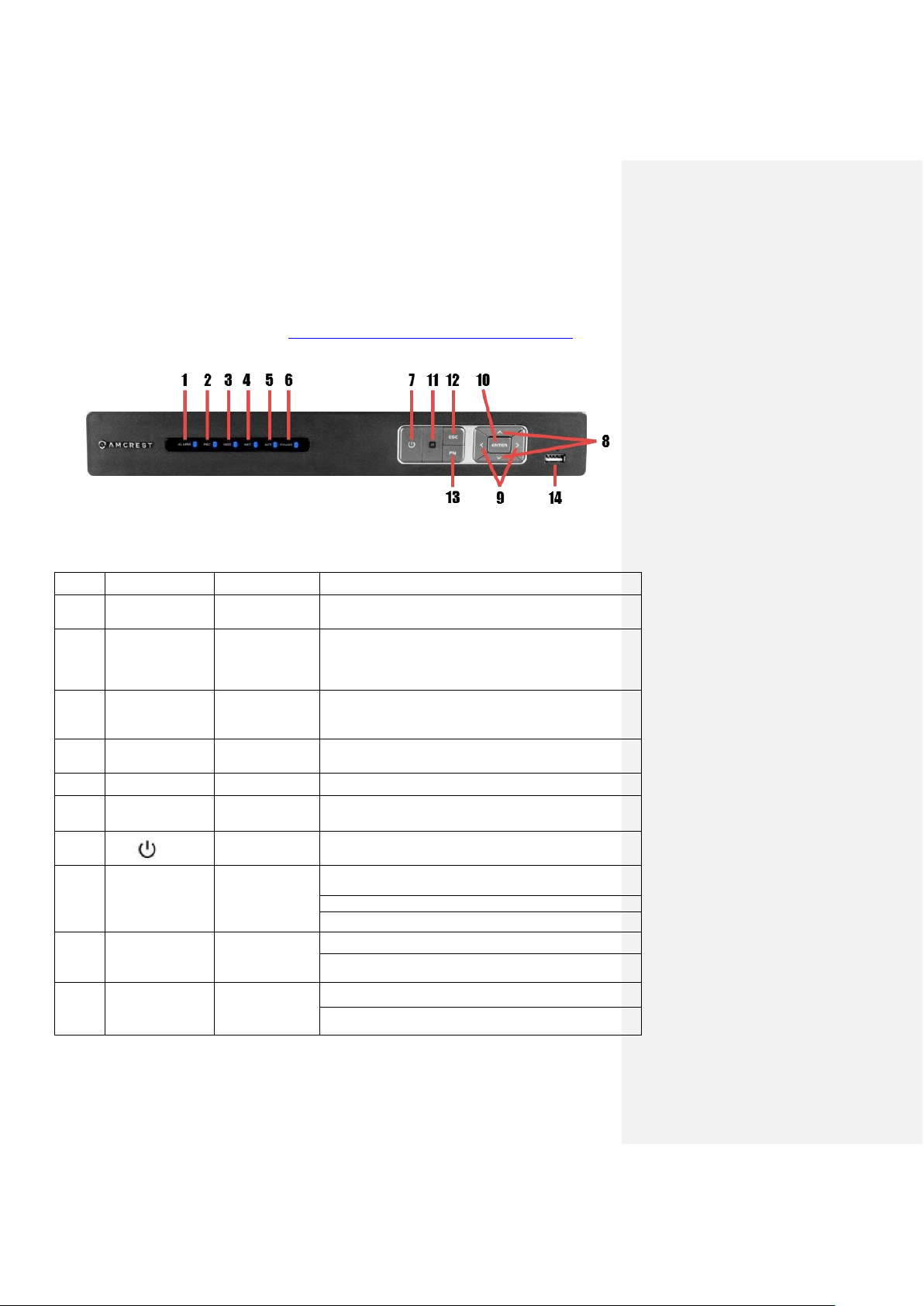
The front panel is shown in Figure 1.
Figure 1
Please refer to the following chart for information on the front panel buttons
#
Icon
Name
Function(s)
1
ALARM
Alarm status
indicator light
When an alarm event occurs, this LED becomes
blue to alert you.
2
REC
Recording status
indicator light
When the NVR is recording footage to the hard
drive, this LED will become blue to alert you.
3
HDD
HDD status
indicator light
When an HDD error occurs or the HDD capacity is
below the specified threshold, this LED becomes blue
to alert you.
4
NET
Network status
indicator light
When a network error occurs or there is no network
connection, this LED becomes blue to alert you.
5
ACT
ENTER
Confirms the current operation.
6
POWER
Power status
indicator light
When the NVR is powered on, this LED will remain
blue.
7
Power button
Press and hold the power button for 3 seconds to boot
up or shut down the NVR.
8
🔺 / 🔻
Up/Down
Activates current controls, modifies settings, and
allows navigating up and down through options.
Increases/Decreases numerals.
Assists in functions such as PTZ menu.
9
< / >
Left/Right
Shifts current activated controls.
When in playback, use these buttons to control the
playback bar.
10
ENTER
Enter
Confirms the current operation.
Goes to the default button.
Front/Back Panel Diagrams & Descriptions Front Panel
2
Goes to the menu.
11
IR receiver
This is used to receive the signal from the remote
control.
12
ESC
Escape
Go to the previous menu or cancel the current
operation.
When in playback, push ESC to restore real-time
monitoring.
13
Fn
Assist
In one-window monitoring, push this button to
display additional functions such as PTZ control and
image color.
Backspace function: in numeric/text control, press
Fn for 1.5 seconds to delete the character before the
cursor.
In motion detection setup, use the Fn button and
directional keys to adjust the settings.
In text mode, push Fn to switch between numeric
and English characters (small/capitalized), etc.
Activates other special functions.
14
USB 2.0 port
USB 2.0 port: connect a mouse, USB storage
device, etc.
Front/Back Panel Diagrams & Descriptions Rear Panel
3
Rear Panel
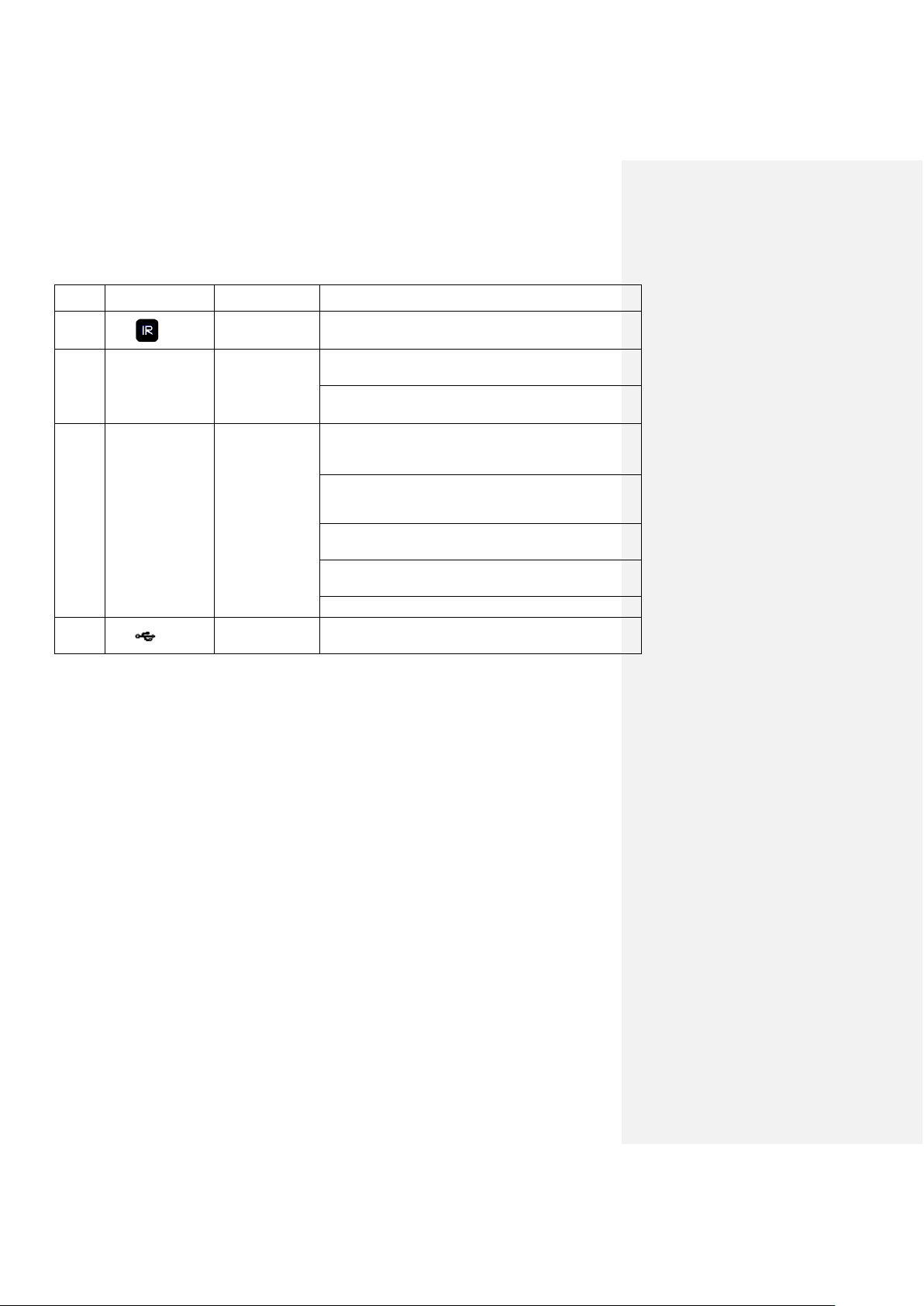
Please refer to the following chart for detailed information on the rear panel ports:
#
Port
Connection
Function
1
USB 2.0 port
USB 2.0 port: connect a mouse,
USB storage device, etc.
2
Network port
10M/100M self-adaptive Ethernet
port. Connects to the network.
3
HDMI
High Definition
Multimedia Interface
port
High definition audio and video
signal output port. It transmits
uncompressed high definition
video and multiple-channel data
to the HDMI port of the display
device. HDMI version is 1.4.
4
VGA
Video Graphics Array
output port
VGA video output port: outputs
analog video signal. It can
connect to a monitor or TV to
view analog video.
5
/
Power input port
Power socket:
● NV1104/NV4108: Input
DC 48V/1.25A/
6
MIC IN
Audio input port
Bidirectional talk input port: this
receives the analog audio signal
output from the devices such as
a microphone.
7
MIC OUT
Audio output port
Audio output port: used to output
the analog audio signal to
devices such as the sound box.
● Bidirectional talk output
● Audio output on 1-
window video monitor
● Audio output on 1-
window video playback
8
PoE
Power-over-Ethernet
port
Built-in switch that supports PoE.
For PoE series products, you
can use this port to provide
power to the network cameras.

Hardware Setup Setting up the cable connections
4
2. Hardware Setup
Before setting up the NVR, you will probably need the following items. The items are not
included:
● A computer monitor or TV with either an HDMI or VGA input
● A power strip with room for 4 large power plugs
● A hard drive for storing video recordings
It is recommended to connect all components of the system as shown below before mounting
any of the cameras. (WiFi IP cameras only need a power connection and can be mounted
without being connected to the NVR.) This is to ensure all components are working. If any
components are not functioning, please contact Amcrest Support.
There will be two parts to this section:
1. Setting up the cable connections (NVR, cameras, monitor)
2. Hard drive installation
A hard drive must be installed in this NVR in order to record or save any footage. If no hard
drive is installed, you can only use the live view functionality of this NVR, which means you still
can use the mobile app or a computer to view your live camera streams remotely.
Note: Using Amcrest Cloud, you can still record directly through the cloud and no hard drive
installation is needed.
Setting up the cable connections
The following instructions will show you how to set up the cables for the NVR, cameras (PoE and
WiFi), as well as a monitor or TV screen.
To set up the NVR’s cable connections, there are 7 major steps:
1. Connect a monitor or TV screen to your NVR. The NVR is compatible with any monitor or
screen that uses a VGA or HDMI connection. For purposes of this guide, we will use a
VGA connection. Take a VGA cable, and connect one end to the VGA port on your
monitor/screen and the other end to the VGA port on the back panel of your NVR.
Hardware Setup Setting up the cable connections
5
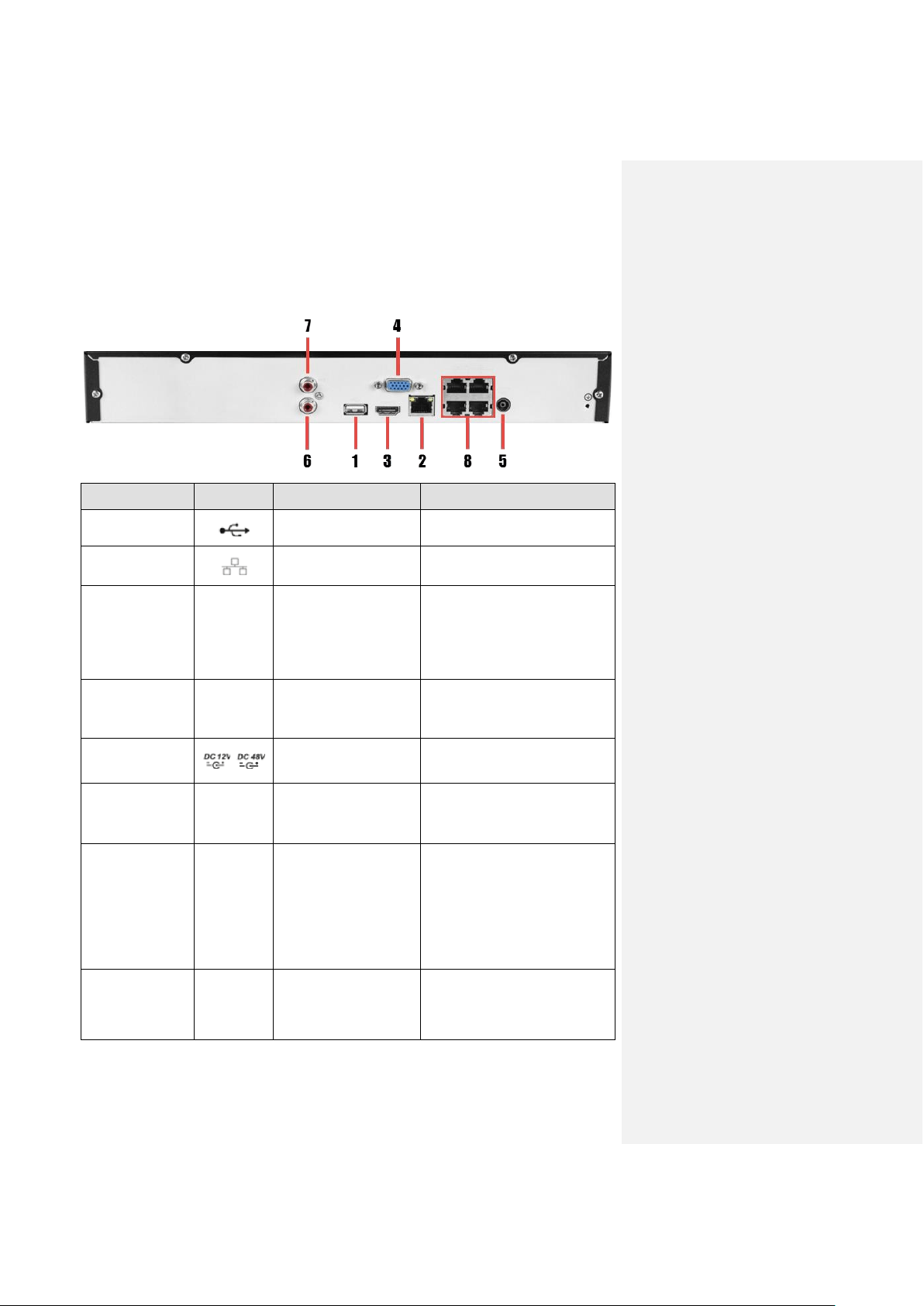
2. Connect a USB mouse to the front of the NVR.
3. Connect an Ethernet cable to your router.
Then, connect the other end of the cable to the NVR.
Hardware Setup Setting up the cable connections
6
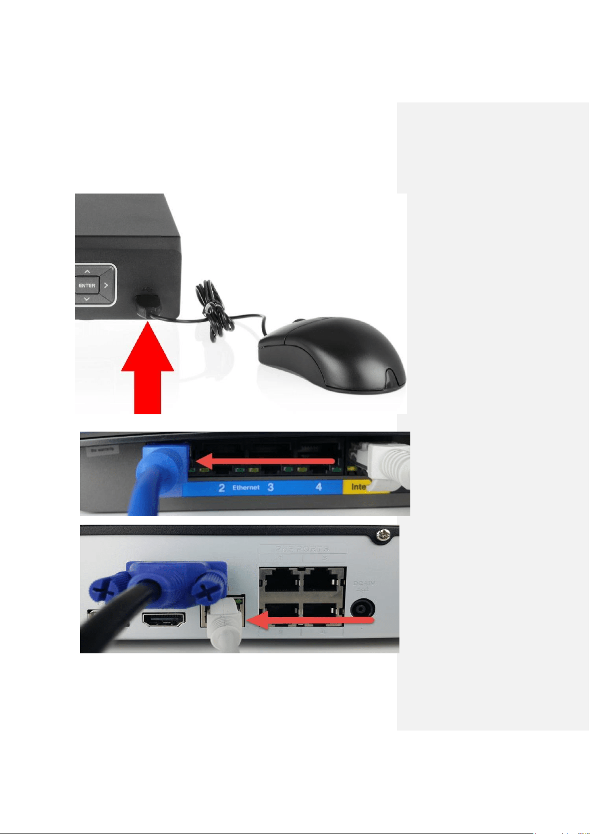
4. Connect cameras to power.
a. For PoE NVRs/cameras: connect an Ethernet cable to the PoE port attached to
the camera.
Then, connect the other end of the Ethernet cable to a PoE port on the NVR.
Note: PoE cameras can either be powered with a PoE connection or with a
standard power adapter (sold separately).
Hardware Setup Setting up the cable connections
7
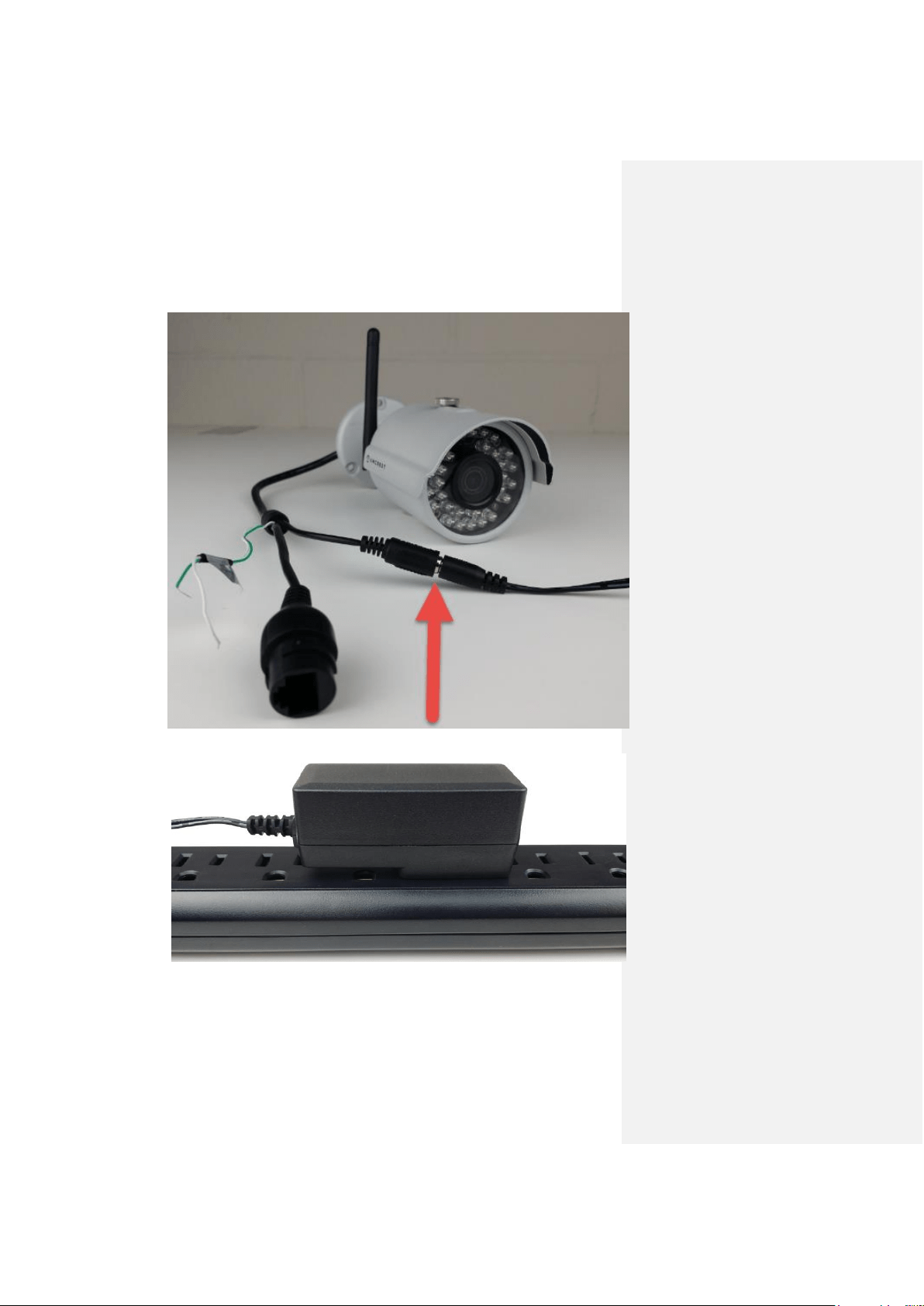
b. For non-PoE NVRs/cameras: Connect the power adapter to the power port
attached to the camera.
Then, plug the adapter into a wall outlet or power strip.
Hardware Setup Setting up the cable connections
8
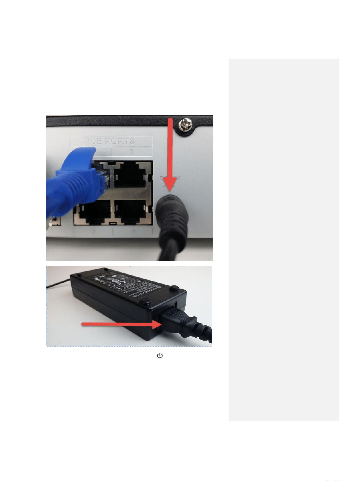
5. Connect the NVR’s power pin (attached to the brick) into the power port on the back of
the NVR.
6. Then, take the power plug and connect it to the brick on one end.
7. Finally, connect the other end of the power cable into a wall outlet or power strip. Your
NVR can now be powered on. Press the power button on the front panel.

Hardware Setup Setting up the cable connections
9
- PLEASE READ BELOW-
Note: Your NVR may not work properly if the following is not accounted for.
Every single NVR comes preset to a video output resolution of 1280x1024. What this means is
that any time an HDMI cable is plugged into an HDTV, it may result with a blank screen even if
the NVR is operational.
If this occurs, please follow the steps below.
Procedure using a VGA cable:
1. Connect your NVR to a computer monitor or TV screen with a VGA cable (the HDMI
cable should not be connected during this process).
2. Boot up your NVR. When the interface loads, you will see the login screen appear. On
the monitor or TV, please make sure the “input” is set to VGA.
3. On your NVR, open the Main Menu by left-clicking once on the live feed screen and,
under the Settings row, click on the System icon. Then, on the new window, click Display
from the list on the left column of options. Change your resolution from 1280x1024 to
1920x1080 and click Apply down below. Your NVR will reset to effect the change.
4. Disconnect the VGA cable and connect your NVR to an HD monitor or TV using an HDMI
cable. Don’t forget to change the input to HDMI on a TV. Your interface will now appear
and you can use your NVR freely.
Display Settings Screen
Hardware Setup Hard drive installation
10
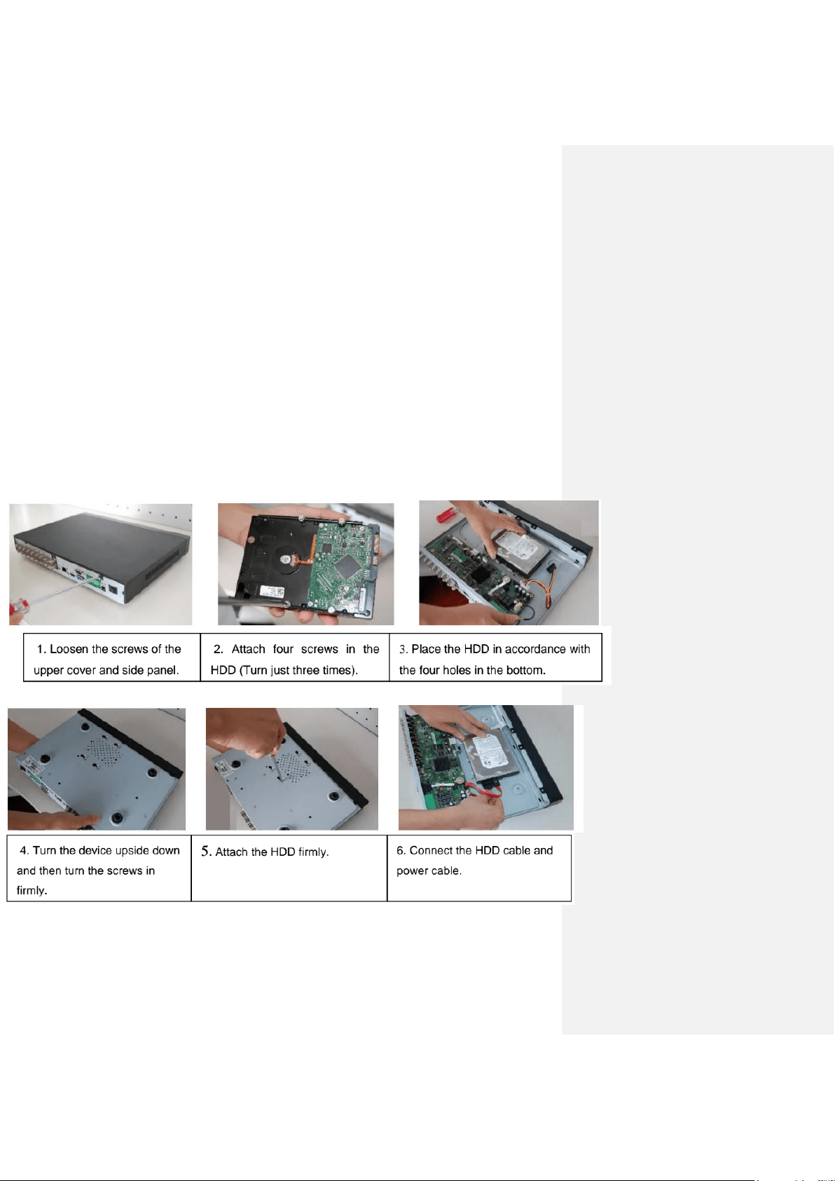
Hard drive installation
A hard drive can be installed if you want to be able to use the NVR to record and save footage
locally (on the NVR). Having a hard drive allows you to configure and use the recording
functionality of this NVR, including playing back previously recorded footage.
The NVR has connections for only 1 hard drive inside the case and the hard drive must be no
bigger than 4TB (Terabytes).
In order to install your hard drive, the following is needed:
● A medium sized (regular) Phillips-head screwdriver - not included
● A hard drive - not included
● Four hard drive fastening screws - included
Note: Before installing the hard drive, make sure the NVR is powered off with the power
cable disconnected.
Hardware Setup Hard drive installation
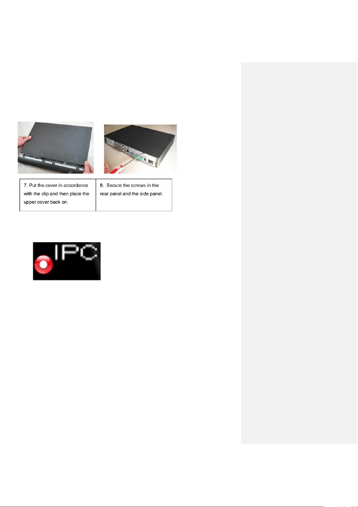
11
Once the hard drive is installed, boot your system and, for any cameras that are configured to be
recording, you will see the following ‘recording’ icon appear in the bottom-left corner of the live
view window for that camera:
Console Setup Logging in
12
3. Console Setup
Logging in
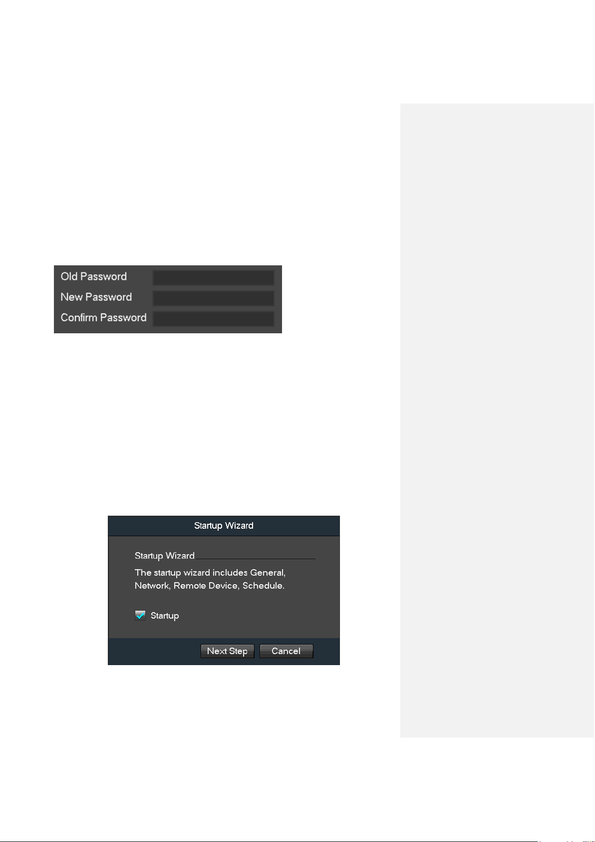
After turning the system on, the default video display shows multiple windows and a page will
appear that asks you to change your password:
First, you will need to enter the default “old” password.
The default password to enter into the Old Password field is: admin
Once you’ve entered “admin” (without quotes) into that field, proceed to enter a new password
into the New Password field, then enter your new password one more time into the Confirm
Password field to confirm it.
Please note that the system consists of two accounts (out of the box):
● Username: admin Password: admin (administrator, local and network)
● Username: default Password: default (hidden user)
After you’re done here, click OK.
Startup Wizard walkthrough
The first page of the Startup Wizard will appear:
Console Setup Startup Wizard walkthrough
13
If you do not want to use the Startup Wizard, or you’ve already gone through it and don’t want it
to keep appearing, unmark the checkbox next to Startup and click Cancel.
Note: Every page from the Startup Wizard that follows can be accessed and modified at any time
through the Main Menu.
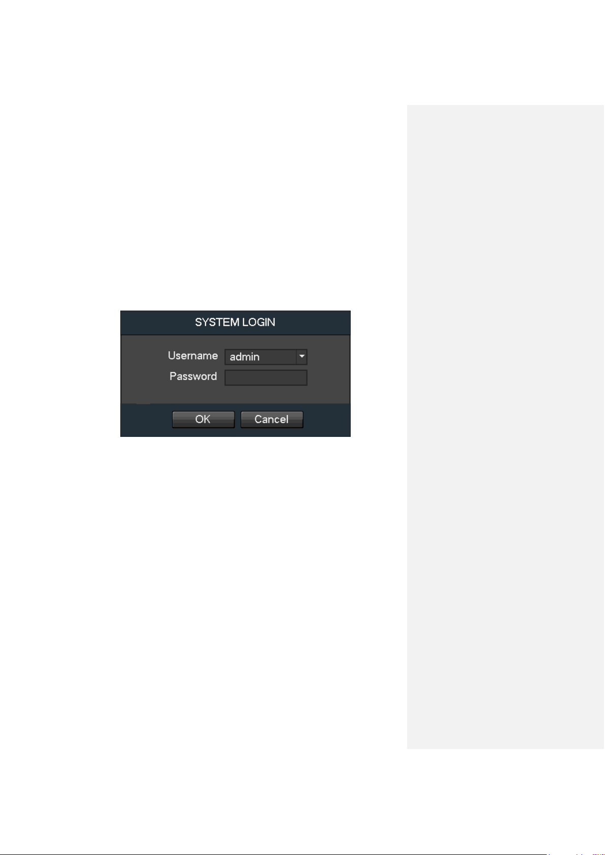
To login to the system for the first time, click Next Step and the login screen will appear.
You will be asked to log in for the first time now. Enter your new credentials:
Username: admin
Password: (your new password)
Note: If three failed logins are attempted within a 30 minute time period, the system will set off an
alarm. After five login failures, the account will be locked.
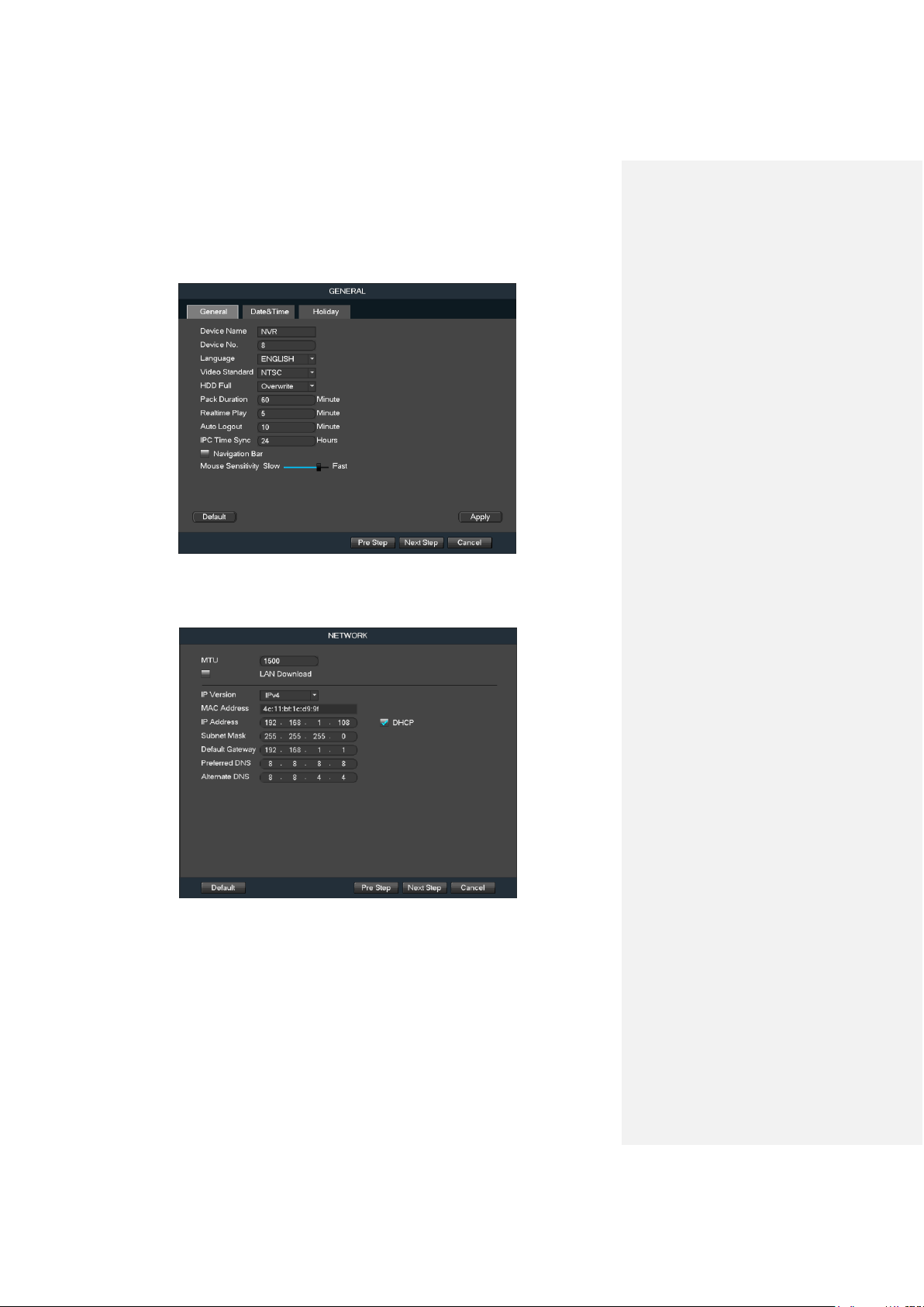
The next screen that comes up is the GENERAL settings screen. Make sure to click the tabs at
the top for Date & Time, as well as Holiday to configure those settings as well. Once you are
satisfied with the settings on this screen, click the Next Step button at the bottom of the screen.
Console Setup Startup Wizard walkthrough
14
The next screen that comes up is the NETWORK settings screen. Unless you have a specific
reason to change these settings, it’s best to leave them as they are. Network access to the NVR
through a computer or mobile app will be covered later on in this guide.
Once you are satisfied with the settings on this screen, click the Next Step button at the bottom
of the screen.
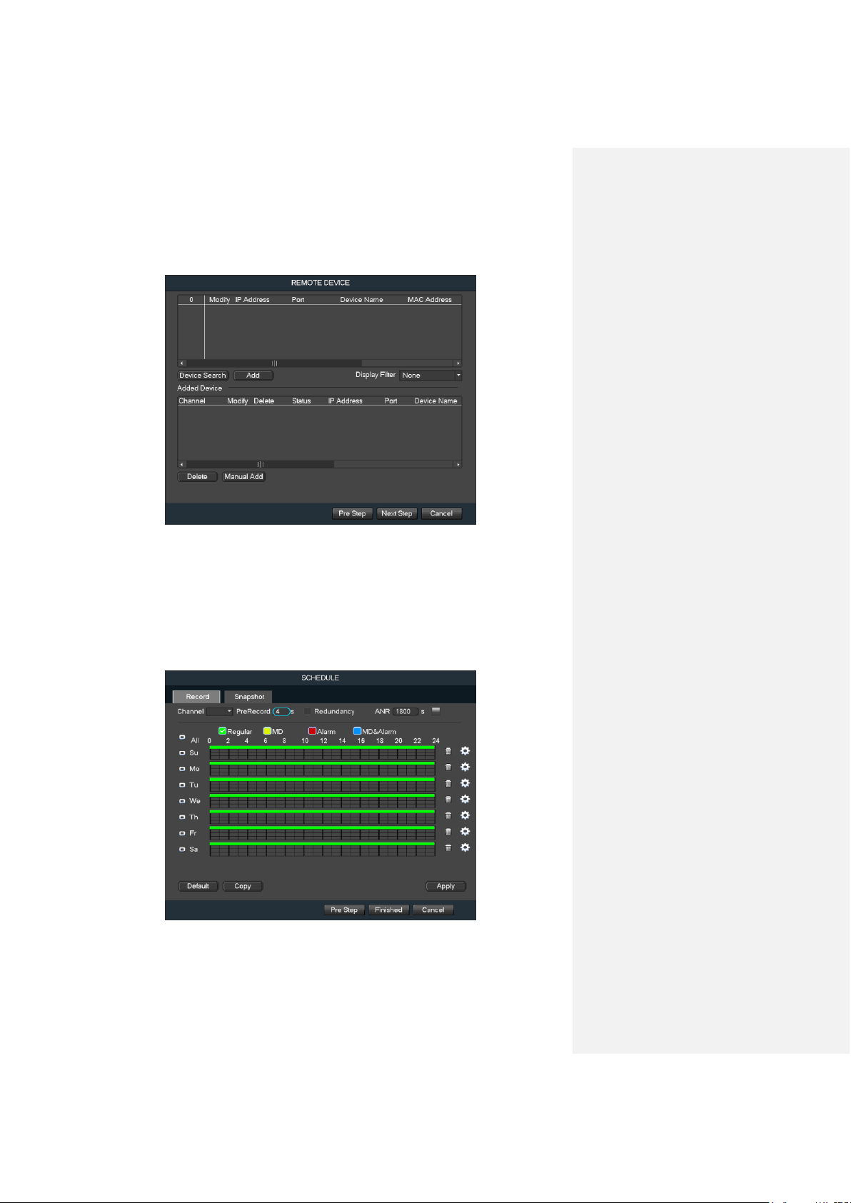
The next screen that comes up is the REMOTE DEVICE settings screen. If you have already
added cameras to your network or connected them directly to this NVR, you will be able to find
and add them to the interface by clicking Device Search, selecting the camera from the results
list, then clicking Add (or by using the Manual Add function). Otherwise, ignore this screen for
now as the adding of both WiFi and PoE cameras will be covered later on in this guide.
Console Setup Startup Wizard walkthrough
15
Once you are satisfied with the settings on this screen, click the Next Step button at the bottom
of the screen.
The final screen you see is the Schedule settings screen. Make sure to click the tabs at the top
for Record and Snapshot to configure those settings as well. Your NVR is configured, by default,
to record everything on all channels 24/7 (this will only actually happen provided you have a hard
drive installed - which will be covered later in this guide). You can also use this screen to set up
motion detection and alarm schedules. Once you are satisfied with the settings on this screen,
click the Finished button at the bottom of the screen.
Console Setup Startup Wizard walkthrough
16
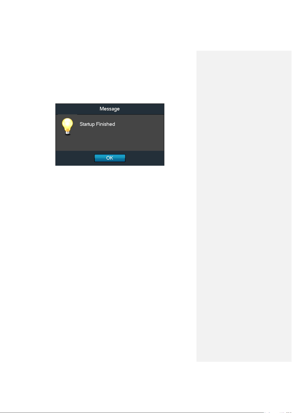
Once the setup process is finished and you have clicked the “Finished” button, you should see
the below dialog box:
Click OK to continue and the next screen you will reach will be the home 4-window (4-channel)
screen for your system.
Before following this guide to the next step, that covers the main menu, you will need to left-click
once or right-click and select ‘Main Menu’ from the right-click menu.
Console Setup Main Menu overview
17
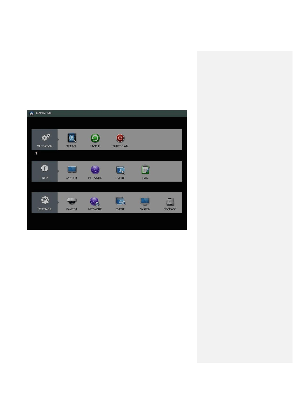
Main Menu overview
The screenshot below is the main menu screen for the Amcrest NVR console interface:
Below are short descriptions for each of the menu items on the main menu:
OPERATION -> SEARCH: Search and playback recorded video that is stored on the hard drive.
OPERATION -> BACKUP: Backup recorded files onto a USB drive.
OPERATION -> SHUTDOWN: Logout, shutdown, or restart the system.
INFO -> SYSTEM: View information about the recordings, hard drive statistics, or version
information.
INFO -> NETWORK: View information about the network or test the network status
INFO -> EVENT: Display information about events that triggered recording.
INFO -> LOG: Display system logs of critical events.
SETTINGS -> CAMERA: Review or edit settings for each camera, including video settings (e.g.
quality, bit rate, color, etc.).
SETTINGS -> NETWORK: Review or edit network settings for the NVR (e.g. email, DDNS, UPnP,
etc.)
SETTINGS -> EVENT: Review or edit settings that trigger recording events (e.g. motion detection,
alarm, etc.).
SETTINGS -> SYSTEM: Review or edit system parameters or configuration, including account
settings (e.g. usernames, etc.).
SETTINGS -> STORAGE: Review or edit storage parameters and settings.
Console Setup Using the device search method
18
Adding cameras
Using the console’s built-in interface, WiFi and PoE IP cameras can be added in 2 ways: using
the device search method and using the direct connection (PoE) method.
Note: ONVIF cameras, or cameras that support the ONVIF protocol can also be added to
this NVR. These steps will be covered after the Using the device search method below.
The device search method is recommended for any user who already has IP cameras (e.g. WiFi
cameras) installed in the home or business. This method uses the NVR’s network scan function
to locate, identify, and add these cameras to the NVR’s interface. The NVR and the previously
set up cameras must be connected to the same local network (your home/business WiFi/router).
The direct connection (PoE) method is the primary recommended method for setting up PoE IP
cameras on your NVR using a direct Ethernet connection. Using this method, you will quickly be
able to see and set up your cameras for the first time all within the NVR’s interface for instant
access to the live video streams.
Using the device search method
Before beginning this process, make sure that the cameras you are trying to add have already
been set up on your network, or at least connected to the router with an Ethernet cable. If the
username and password were not set up previously, you can still set them up on the NVR and
access the feeds with the default username and password.
It is recommended that you identify that camera’s IP address before continuing. But, if you don’t
have the IP address, you can just try adding each list item in the step below until your camera’s
live feed appears on the NVR.
Note: Changing your default password is always highly recommended to secure access to your
cameras.
1. Log into your NVR console’s built-in interface using your credentials. Refer to Part 3 of
this guide, Console Setup > Logging in.
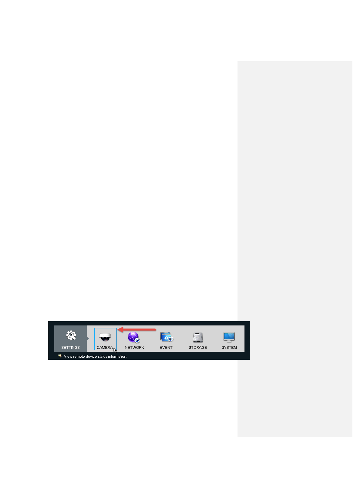
2. Open the main menu by left-clicking once, or right-clicking then left-clicking MAIN MENU
from the right-click menu.
3. Click CAMERA from the bottom SETTINGS row.
4. Click REMOTE from the left navigation panel, then click the REMOTE tab on the right to
get to the device search page.
Console Setup Using the device search method
19
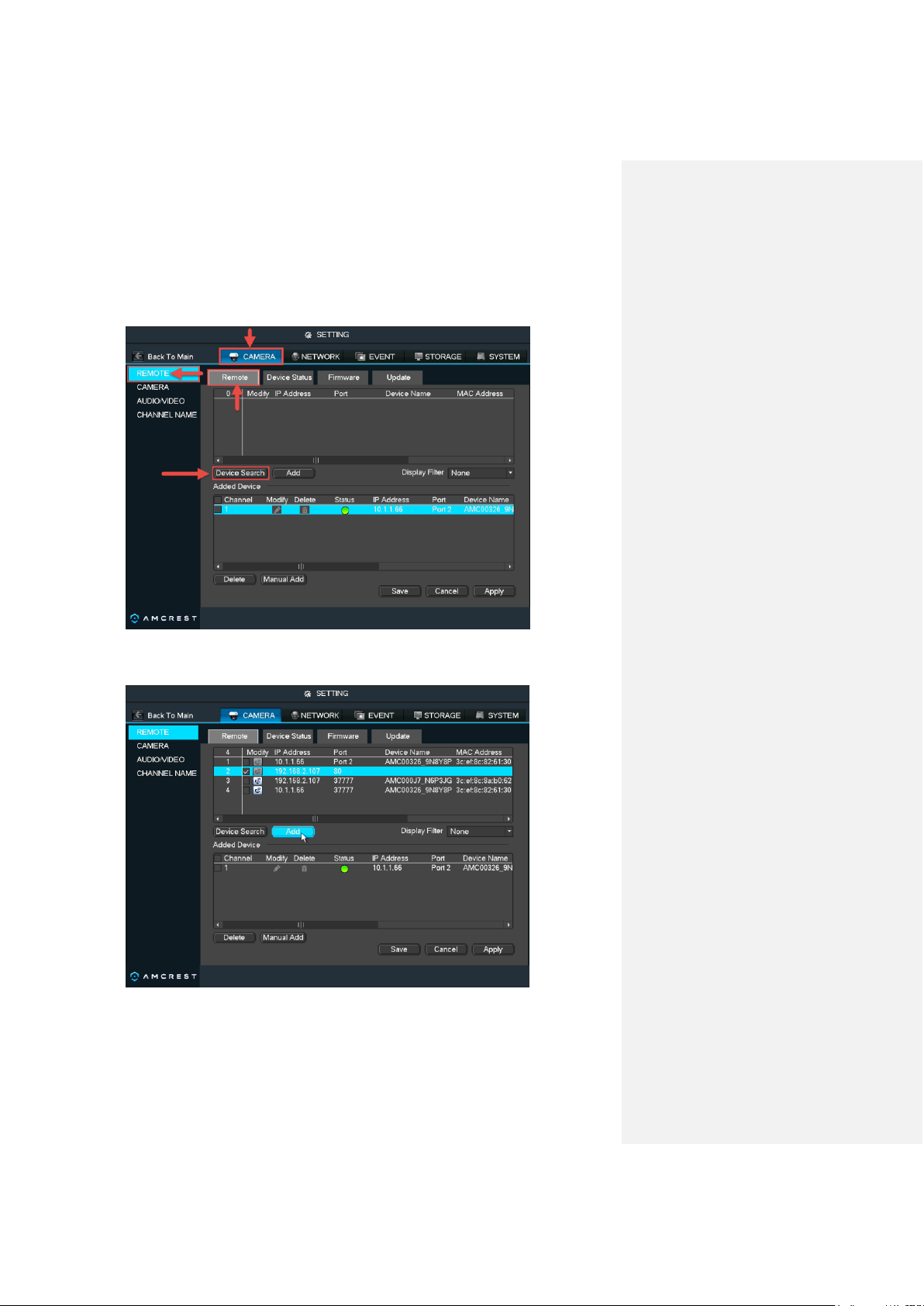
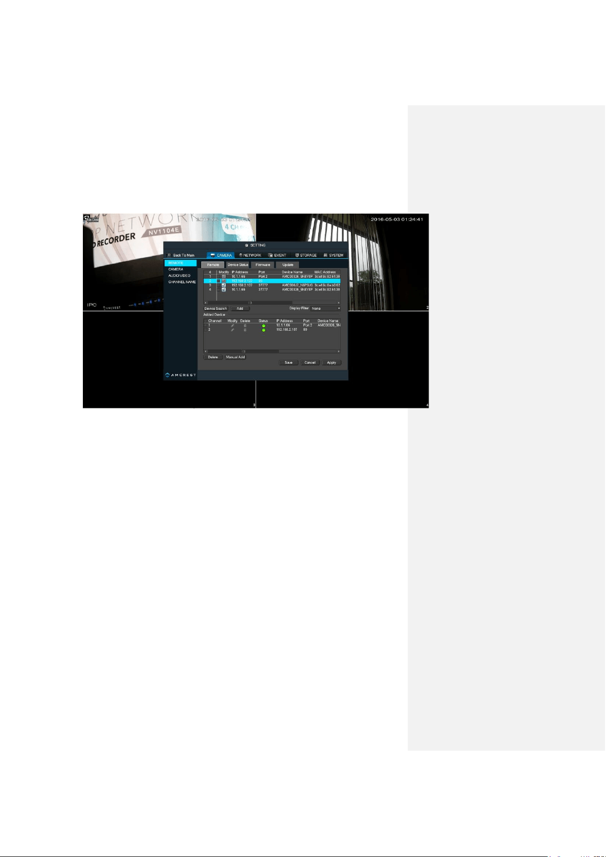
5. Then, find and click the Device Search button to get the list of network-connected
devices.
6. From the list, choose the IP address for the camera you want to add. Then, mark the
check box to the left of the list item for that camera and click Add.
Console Setup Using the device search method
20
7. The selected list item will now be shown in the Added Device table below and
the feed may appear if the default credentials have not been changed.
The NVR will automatically use the default username and password of “admin” and
“admin”, respectively. However, it is strongly recommended to change the default
password to secure your cameras.
Changing the password for your IP cameras can only be done by accessing them
individually through their built-in interfaces by using their IP addresses. It cannot be done
through this NVR. The NVR will only accept the current username and password to be
able to pull the stream through.
In order to access the camera’s interface to change the username and password, please
refer to the manufacturer's documentation for that camera.
Once finished updating the password, you can come back to this device search screen
on the NVR and click pencil icon under Modify once a camera has been added to the
Added Device list. This will bring up a screen where you can update the username and
password.
When finished adding cameras and entering the correct login credentials, the live stream
should appear behind the setup screen in the background as shown above. Make sure to
click Save, then Apply before closing this window.
Console Setup Adding ONVIF cameras
21
Adding ONVIF cameras
Using ONVIF cameras or adding cameras with the ONVIF protocol can be a very efficient way of
using older or outdated cameras. In addition, using ONVIF also makes it easy to consolidate
cameras from different manufacturers all onto the same NVR because ONVIF is an industry
standard that can allow that kind of cross-compatibility.
The below steps should be followed after all steps in the above Using the device search
method process have been followed and completed.
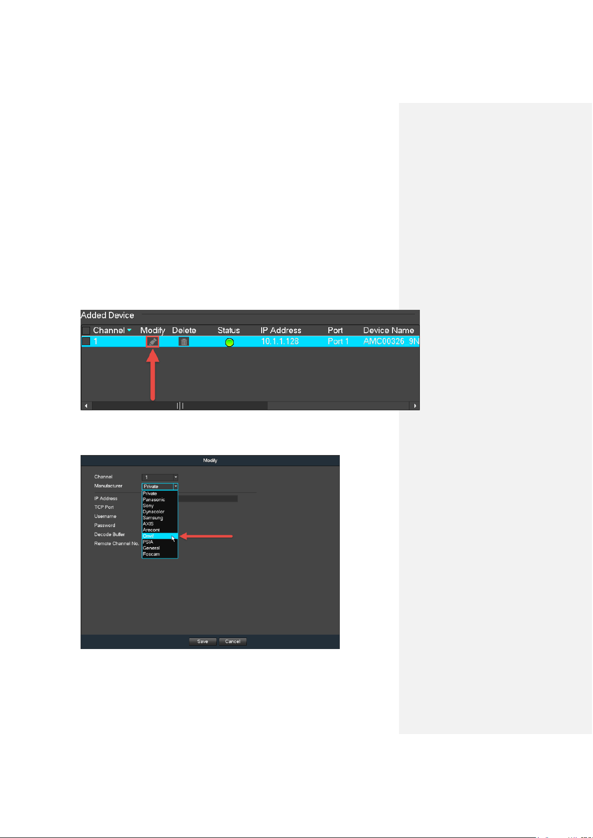
1. Once your device has been added to the Added Device table, click the pencil
icon under Modify:
This will take you to the Modify page.
2. Click the down arrow next to Manufacturer and select Onvif from the dropdown:
Console Setup Adding ONVIF cameras
22
This will make a different set of options appear for you to configure.
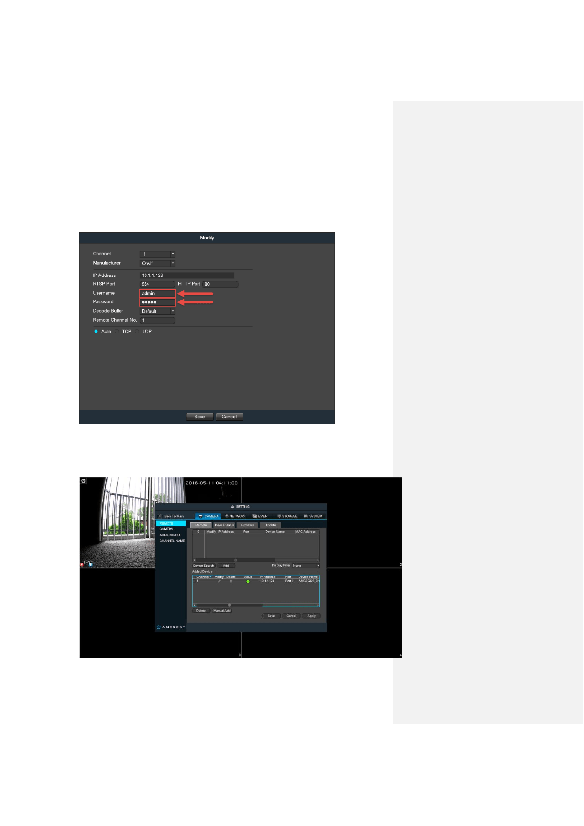
3. It is recommended to not change any of the fields at this point, unless you know
what you are doing. However, make sure you update the username and password to
match that camera’s specific login credentials:
When finished, click Save down below.
4. This will take you back to the previous Remote > Remote (Device Search) page.
Make sure to click Apply before leaving this page by clicking Save.
Motion Detection & Recording Setup Setting up recording schedules
23
4. Motion Detection & Recording Setup
This section will cover how to set up your NVR’s scheduled recordings for both regular and
motion detection recordings. It will also cover how to set up email alerts with snapshots.
Note: The NVR can only be set up to save regular and motion detection recordings if a
hard drive has already been installed. However, email alerts with snapshots can still work
without a hard drive installed.
A hard drive is not included with this system. Once purchased separately, for hard drive
installation instructions, please refer to part 3 of this guide: Hardware Setup > Hard drive
installation.
The following setup processes will be shown using the NVR console’s built-in interface. However,
these same steps can also be done through the web interface on a computer. Despite the
difference in appearance, the settings pages have the exact same organizational structure.
When motion detection has been set up correctly on this system, you will see the following icon
appear on your cameras’ live view windows when motion detection has been triggered:
Setting up recording schedules
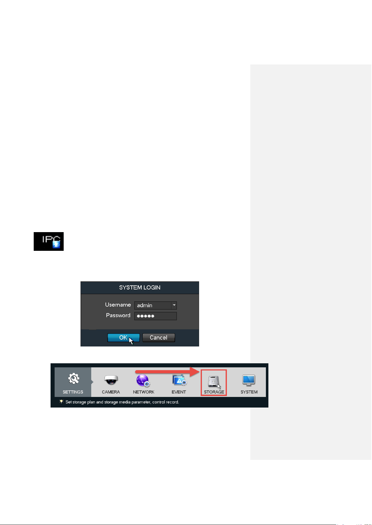
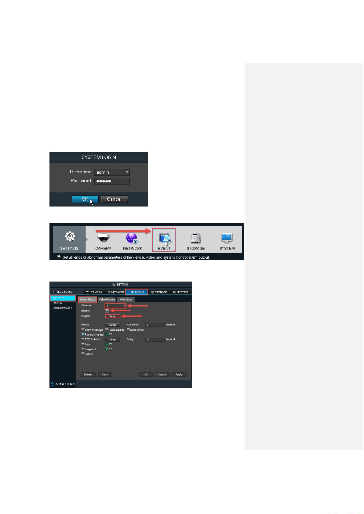
1. Log into your NVR with your username and password:
2. Open the MAIN MENU, then click STORAGE in the SETTINGS row:
Motion Detection & Recording Setup Setting up recording schedules
24
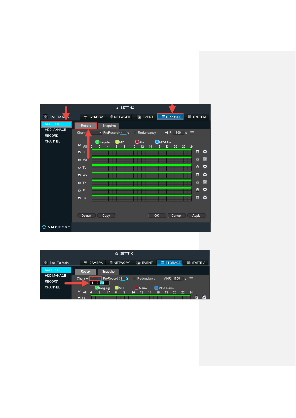
3. Make sure you are on the SCHEDULE > Record page. This is where you can
configure the times and days you would like different kinds of recordings to happen.
4. To choose a channel (or camera) for which to configure the recording schedules,
click the number next to Channel, then select either a single channel or All:
5. By default, the NVR will have the schedule configured to record regularly 24/7.
Notice the green bars going across each day of the week. Also note that the NVR uses
military time, that is, from 0 to 24 instead of from 12 a.m. to 12 a.m.
Motion Detection & Recording Setup Setting up recording schedules
25
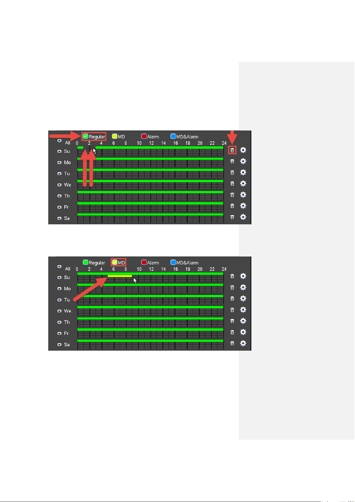
To change which hours you would like the NVR to record, make sure the Regular
checkbox is checked, then click the blocks in the grid. You can also click and drag to add
or remove multiple block at a time. Each block represents one hour:
Click the trash can icon to the right of any day to clear the entire row of all green blocks.
6. To add or remove motion detection blocks to the grid, mark the checkbox next to
MD, then click individual cells or click-and-drag for multiple blocks:
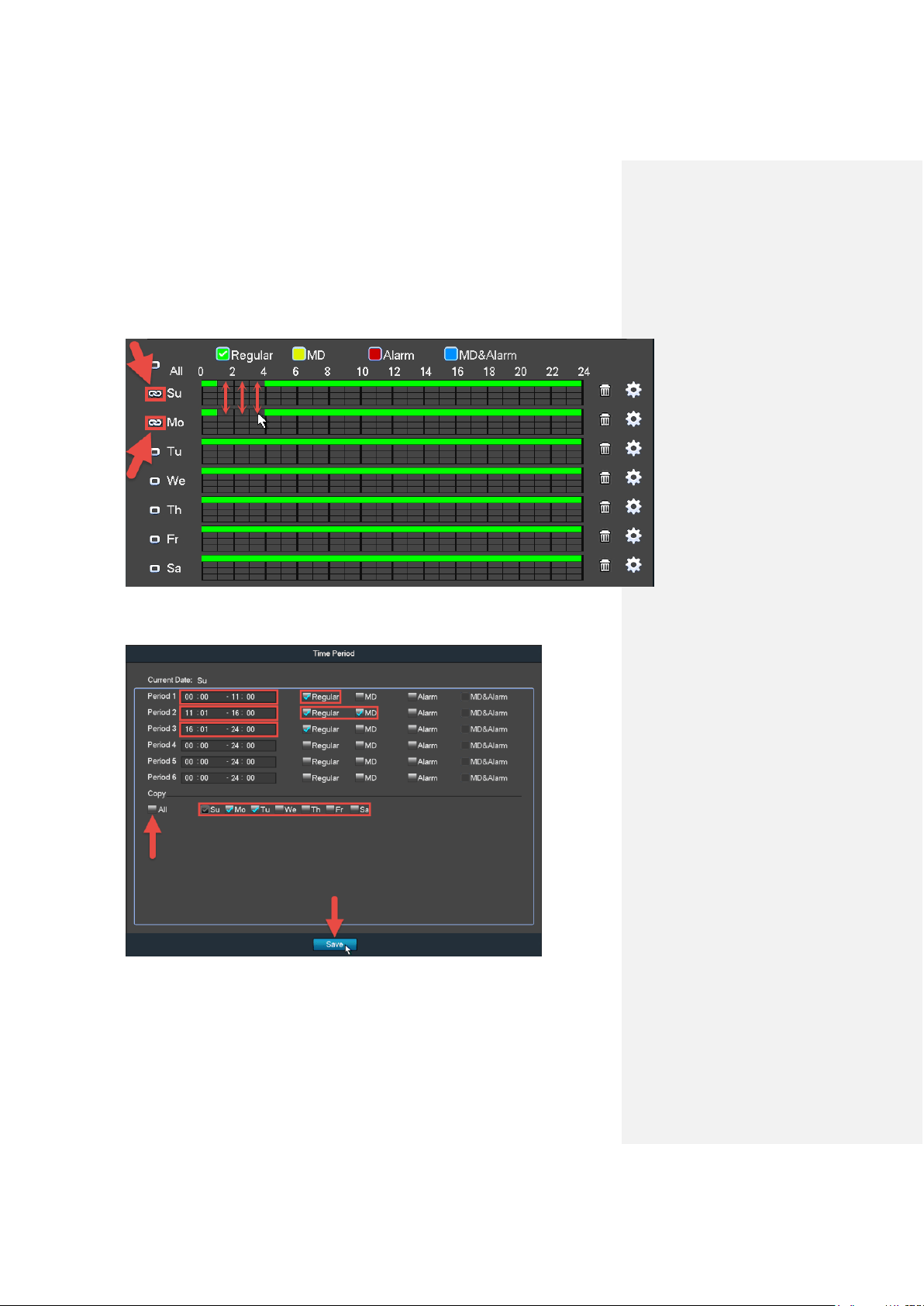
7. To the left of each day, there are small boxes which can be marked to “link”
different days together. This is useful if you want to save time by instantly making
changes to multiple days simultaneously.
Motion Detection & Recording Setup Setting up recording schedules
26
In the below example, Sunday and Monday are linked, so any blocks that are added or
removed for Sunday will automatically and immediately reflect the same for Monday and
vice versa:
8. Another way to configure recording schedules is by using setting the time
periods. Click the ‘gear’ icon to the far right of any day to open the Time Period page:
Here, the periods (Periods 1 - 6) must be in specified in chronological order. You can set
either Regular, MD, or both with the checkboxes to the right. You can also copy the time
period settings over to other days by checking them individually or checking All. Make
sure to click Save when finished.
Motion Detection & Recording Setup Setting up recording schedules
27
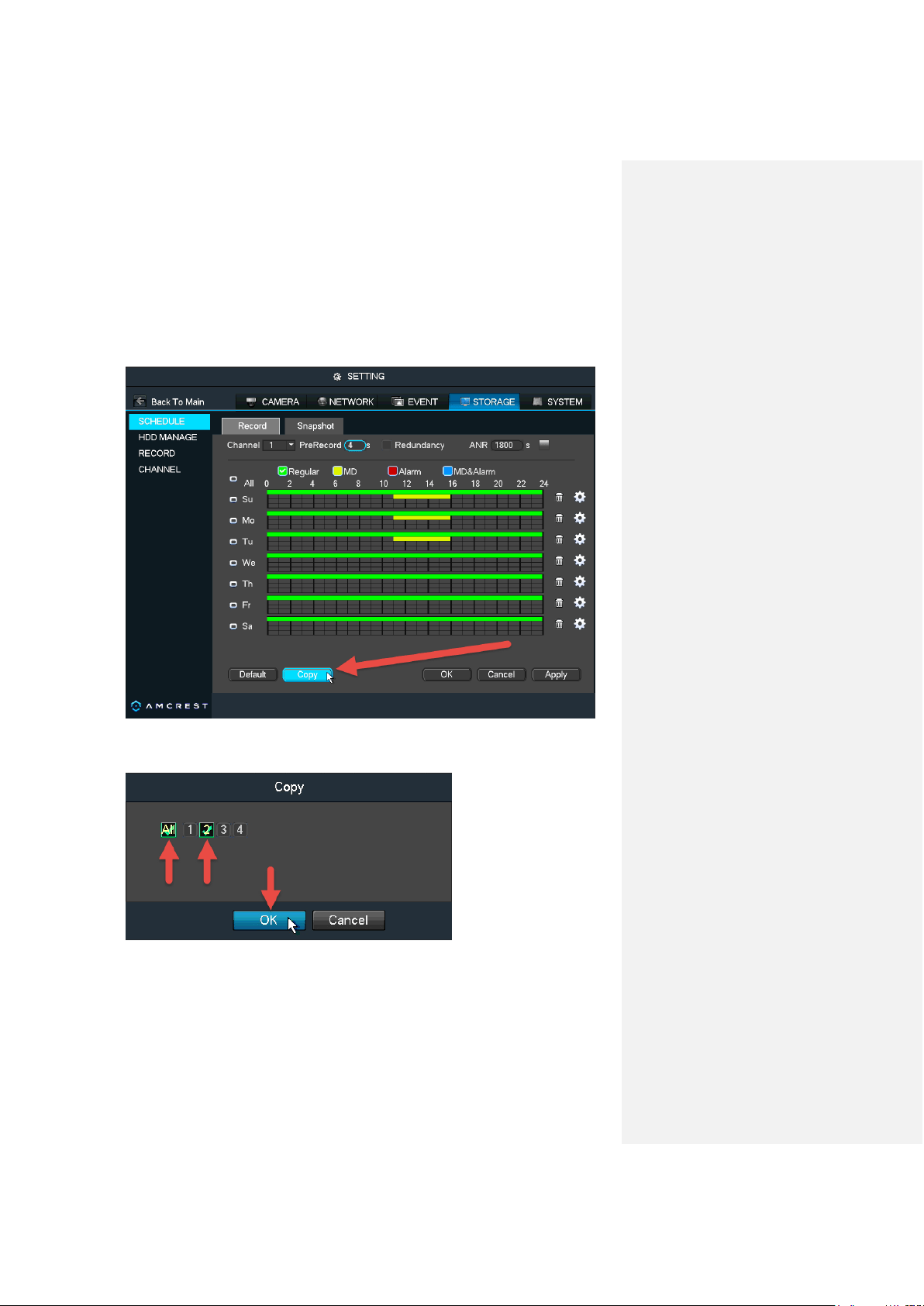
9. Now that you’ve finished configuring the recording schedules, you may need to
copy these settings over to another channel (or camera). By default, Channel 1 will be
selected when you visit this page. Unless you immediately selected All in the channel
window from step 4 above, note that you can copy these settings directly over to another
channel by clicking Copy down below:
In the Copy window, you can select individual channels for any cameras you have added
to the NVR or select All:
Click OK when finished.
10. When finished on this screen, click Apply to save your changes.
Motion Detection & Recording Setup Setting up motion detection and email alerts
28
Setting up motion detection and email alerts
Your NVR will only save motion detection recordings if you have a hard drive installed. However,
you can still receive email alerts with snapshots without a hard drive installed.
1. Log into your NVR with your username and password:
2. Open the MAIN MENU, then click EVENT in the SETTINGS row:
3. Make sure you are on the DETECT > MotionDetect page. This is the main
configuration page for motion detection:
Change your channel (or camera) by clicking Channel and selecting from any cameras
currently added to the NVR. You can also select All. Make sure the Enable checkbox is
checked. Then, click Setup next to Region to configure the motion detection areas.
Motion Detection & Recording Setup Setting up motion detection and email alerts
29
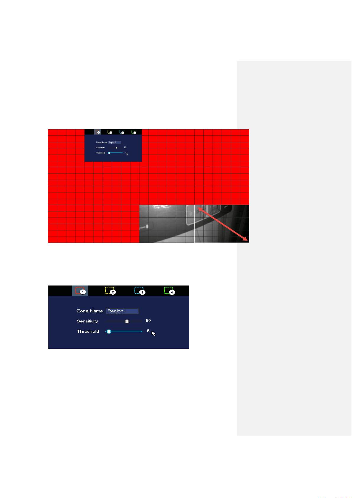
4. You can set up ‘regions’ for motion detection using the region grid on your NVR.
By default, the entire area of view for your cameras will be highlighted with red blocks.
This means that the entire field of view is active for motion detection:
Any red blocks that you click or click-and-drag to remove will not be active for motion
detection. Motion detection will not work for any portion of the screen that is clear.
If you hover your mouse pointer over the top-center edge of this window, another small
window will appear with options to configure sensitivity and threshold settings as well
as to choose from up to four regions.
Sensitivity - is the measure of how many pixels on the screen need to change before
being considered motion. 0 is the lowest value and 100 is the highest.
In plain English: Sensitivity is the difference between a squirrel running up a tree, versus
a big dog running up to and barking at that tree. A squirrel would trigger motion detection
at a higher sensitivity because it takes less change or movement to qualify as motion. But
the dog would trigger motion detection at a lower sensitivity because it takes more
change or movement to qualify as motion.

Motion Detection & Recording Setup Setting up motion detection and email alerts
30
Threshold - is the degree of movement that needs to occur before the motion is defined
as a motion event and is triggered. 0 is the lowest value and 100 is the highest.
In plain English: Threshold is the difference between a car driving quickly by on a street
and a car driving into the field of view, slowing down, and turning into a driveway. The car
driving past would not trigger motion detection based on a certain threshold setting, but
the parking car would trigger motion detection with that same threshold setting. The
higher the threshold, the more time motion needs to occur before motion detection is
triggered. The lower the threshold, the less time motion needs to occur before motion
detection is triggered.
If sensitivity is set to 100 and threshold to 0, motion detection will be triggered most
easily by almost any change in the field of view, large or small. But if sensitivity is set to 0
and threshold to 100, motion detection will be extremely difficult to trigger.
The four regions are all different colors so you can customize the field of view of any
camera to your highly specific preferences.
5. To choose another region, hover your mouse pointer near the top-center of the
region window, and a small window will appear. Keep your mouse pointer inside that
small window and select either region 2, 3, or 4:
You will be able to click individual blocks or click-and-drag an area with the new selected
color to highlight portions of the screen. Each new region (or color) has its own unique
sensitivity and threshold settings. The different regions/colors can also overlap one
another.
Motion Detection & Recording Setup Setting up motion detection and email alerts
31
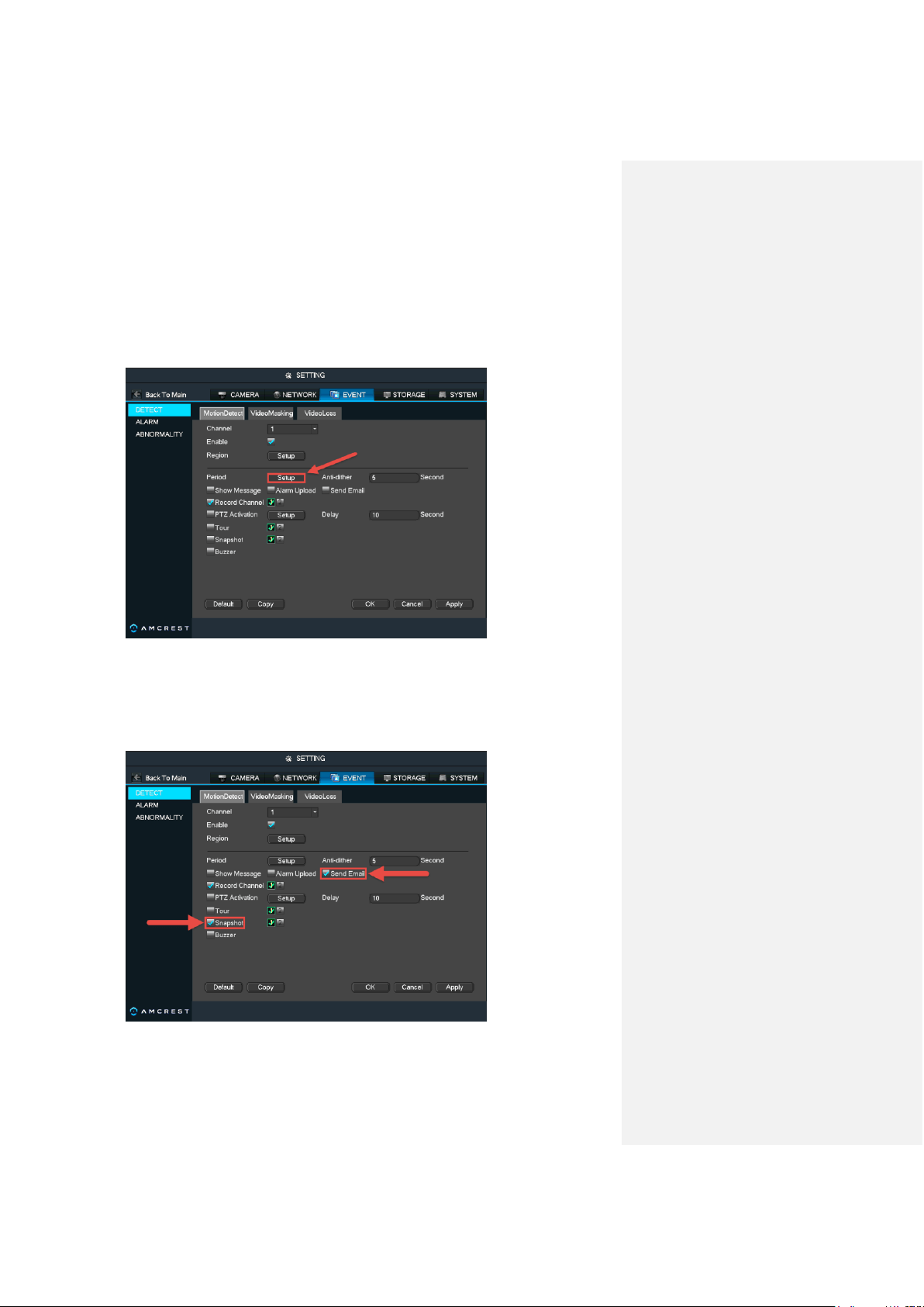
6. You can also adjust the motion detection schedules directly from this settings
page by clicking Setup next to Period:
The Period Setup page works very similarly to the recording schedule page featured in
the previous section in part 5 of this guide: Motion Detection & Recording Setup >
Setting up recording schedules.
7. Next, if you want to receive email alerts with snapshots from your motion
detection events, check the boxes for Send Email and Snapshot:
Motion Detection & Recording Setup Setting up motion detection and email alerts
32
8. Once you have set up your settings for one channel, you can copy them to
another channel. If you did not select All after clicking Channel as described in step 3,
click Copy, select channels to copy to, then click OK:
9. Click Apply to save all the settings made on this page.
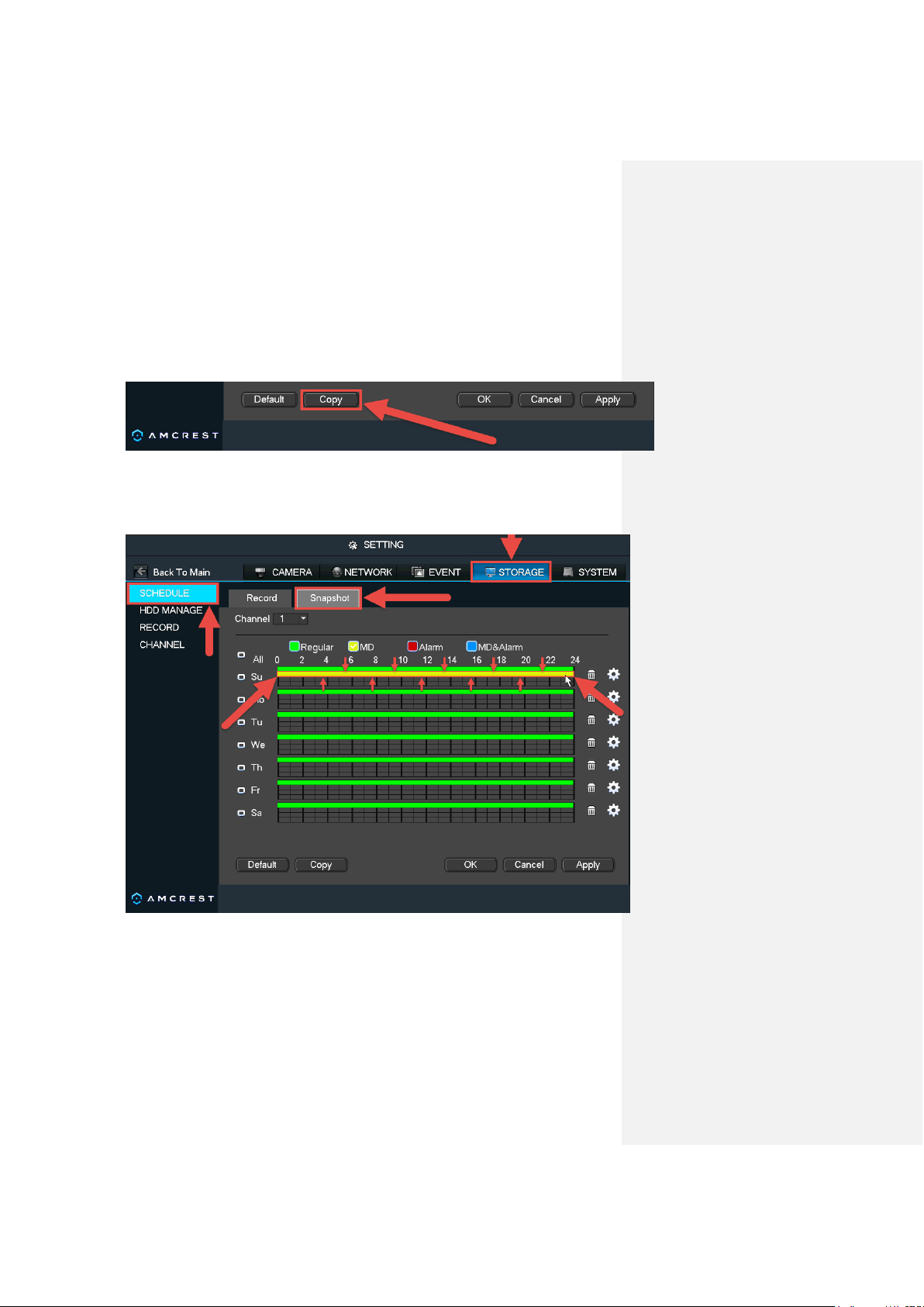
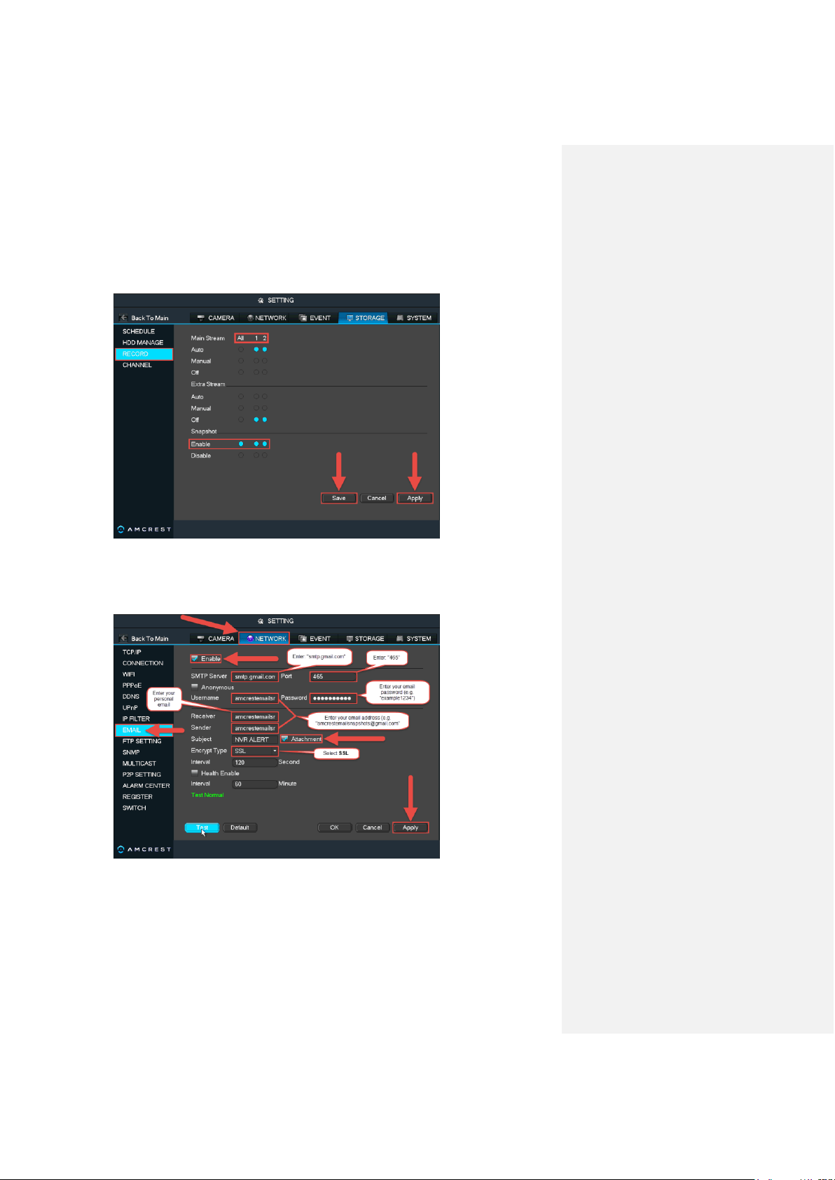
10. Click the STORAGE tab on the top row, then click SCHEDULE > Snapshot to get
to the snapshot schedule settings page:
Here, you can set up the snapshot schedule just like you set up the recording schedule.
Please refer to the earlier section of part 5 of this guide: Motion Detection & Recording
Setup > Setting up regular and motion detection recording schedules.
Motion Detection & Recording Setup Setting up motion detection and email alerts
33
11. Next, click RECORD from the left navigation panel, and click the radio buttons
under Snapshot to select the desired channels:
Make sure to click Apply, then Save before leaving this page.
12. Next, click the NETWORK tab on the top row, then click EMAIL from the left
navigation panel:
The recommended method for this step is to create a new Gmail account that is
dedicated to sending you email alert snapshots for motion detection. This is useful
because, then, you don’t have to change any of your own personal email’s settings.
Using a Gmail account is also the easiest way to set up email alerts which could
otherwise be somewhat technical and difficult.
Motion Detection & Recording Setup Setting up motion detection and email alerts
34
This does not mean that you now have to log into a second, separate email account just
to see your email alerts - because this email will forward all your email alerts to your
personal email. Regardless, it is still recommended to save your email and password
information for this new Gmail account.
Start by making sure the box is checked next to Enable. Then, enter the SMTP Server
which, for Gmail, is: “smtp.gmail.com”. The port number will be: “465”.
In the Username field, enter your new Gmail account’s address. For example:
“amcrestemailsnapshots@gmail.com”. Then, enter the password for this account in the
Password field.
In the Receiver field, enter your own personal email account’s address. For example:
“myemail@website.com”.
Note: In the above example, the Receiver and Sender fields have the same email
address. You can do this as well. However, it is recommended to enter your personal
email in the Receiver field.
Then, enter your new Gmail account address in the Sender field. For example:
“amcrestemailsnapshots@gmail.com”.
Make sure the box is checked next to Attachment. Then, make sure SSL is selected in
the Encrypt Type field.
Finally, click Apply in the bottom-right of this window to save all your settings.
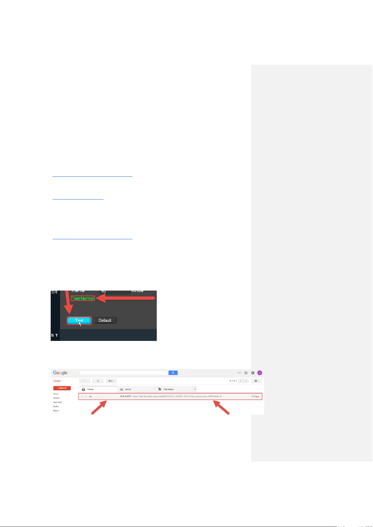
13. Now, we want to make sure the email setup is working properly. To do this, click
Test in the bottom-left:
If the setup was successful, you will get the Test Normal message after clicking Test.
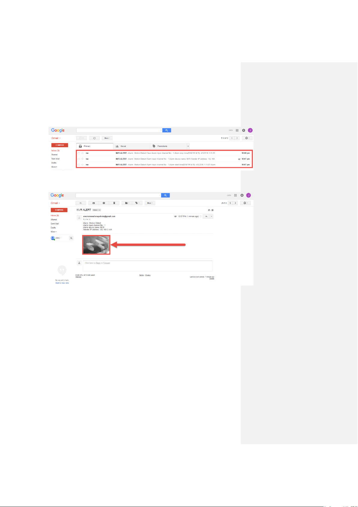
14. Next, check your new Gmail account to see if you received the email test:
Computer Access Setup
35
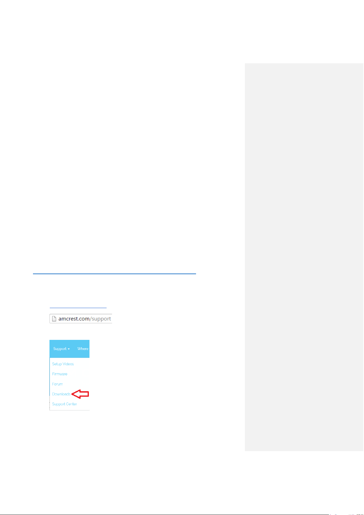
15. Now, whenever your camera detects motion, you will get email alerts sent to your
personal email from this new Gmail account:
This will include an email with a snapshot of what was seen when motion detection was
triggered:
5. Computer Access Setup
There are 2 ways to access your NVR from a computer (laptop or desktop) which are: locally or
remotely.
Local Access: Logging into your NVR’s web interface from a computer or laptop device
connected to the same network as your NVR (home, office, etc.).
Remote Access: Logging into your NVR’s web interface from a computer or laptop device
connected to a network outside of your home or business network (coffee shop, work computer,
etc.)
Local access is preferred by those who, for security reasons or personal preference, do not wish
to make their NVR accessible from outside their network. However, there are several options
available for remote access that use standardized and secure network protocols including SSL,
TLS, DDNS, etc. Most other users require remote network access by way of their smartphones,
tablets, laptops, or computers, wherever they are.
Computer Access Setup Amcrest IP Config Software method
36
The following section will cover both means of access (local and remote). Keep in mind that any
user can have both local and remote access simultaneously if they so choose.
Before accessing your NVR through a web browser, the following two steps must be
completed:
1. You must access the NVR’s web interface with its IP address.
2. You must install the Amcrest web browser plugin.
An IP address is just an identifier given to any devices that connect to a network. People use
names, but internet-connected devices use a set of numbers called an IP address to talk to each
other. Once you have the IP address, your computer will be able to find and communicate with
your NVR.
A browser plugin is just like a translator. Using your NVR by itself, without a computer (the built-
in interface featured in previous parts of this guide) is different than using it on your computer. By
using the NVR on your computer through a web browser, you need to introduce a new piece of
software that allows your computer to understand the language that the NVR speaks in a way
that a computer can understand. That’s what the browser plugin is for.
There are 2 ways to access the NVR’s web interface: (1) Amcrest IP Config Software method
and the built-in interface method.
Amcrest IP Config Software method
Amcrest IP Config Software can be installed for free onto your computer from Amcrest’s official
website. The IP Config Software is available for both Windows and Mac operating systems. To
get directly to the downloads page, use this link:
https://amcrest.zendesk.com/hc/en-us/categories/201939038-All-Downloads
Otherwise, the steps below will walk you through how to download, install, and use Amcrest IP
Config Software:
1. Log onto your computer, open your web browser of choice, and go to
www.amcrest.com/support:
2. Then, hover over the Support tab up top and choose Downloads from the dropdown.
Computer Access Setup Amcrest IP Config Software method
37
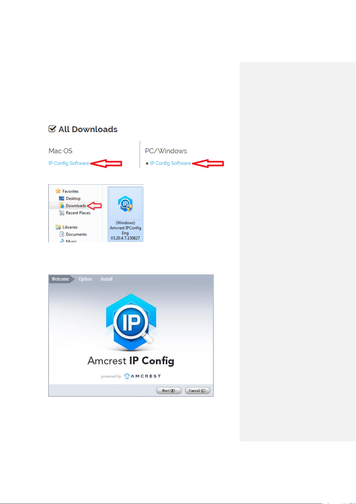
3. This brings you to the downloads page. Click the IP Config Software download link on
this page for either Windows or Mac.
4. Find the download in your Downloads folder, and click it to open the installer.
5. You will be asked to allow this program to make changes to your computer with a pop-up
window, click Yes.
6. Once you see the first page of the installer wizard, click Next to continue.
Computer Access Setup Amcrest IP Config Software method
38
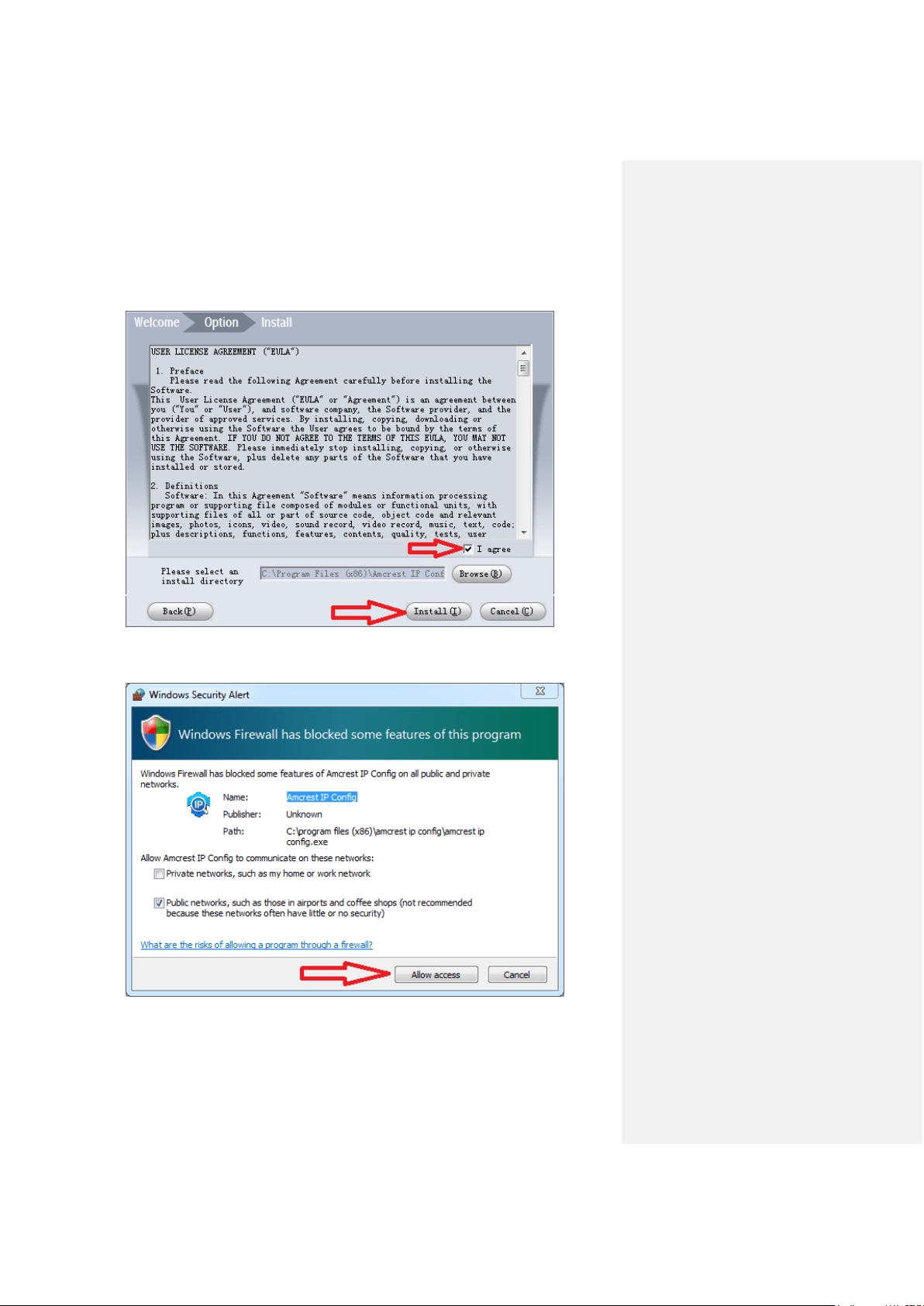
7. On the next page, check the box next to “I agree”, then click Install.
8. After the progress bar completes, if you see a Windows Security Alert popup, click Allow
access.
Computer Access Setup Amcrest IP Config Software method
39
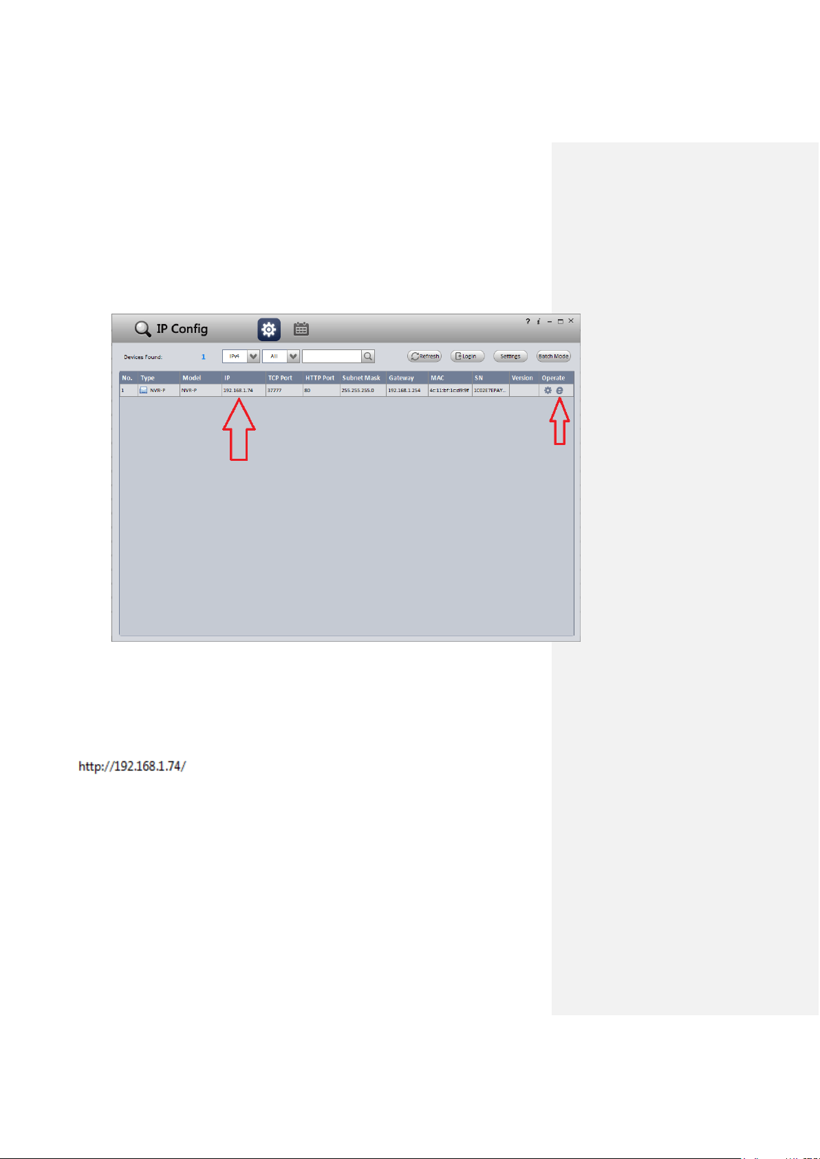
9. This brings you to the main screen of Amcrest IP Config Software. Your NVR will
automatically be found on your network and appear in the list (if properly connected with
an Ethernet cable to your router). You will also see the IP address associated with your
NVR.
The “e” icon to the right allows you to launch directly into your web browser from this
screen.
Note: This “e” icon will automatically take your NVR’s IP address and use your computer’s
“default” web browser to access and log into your NVR. If your default browser is not Internet
Explorer, you can write down the IP address from the Amcrest IP Config Software (IP address
located above), open up Internet Explorer yourself, and type that into the search bar to get to the
login screen. Typing your IP address directly into the search bar will look something like this:
Computer Access Setup Built-in interface method
40
Built-in interface method
1. Boot up and log into your NVR system (as explained in previous steps of this guide).
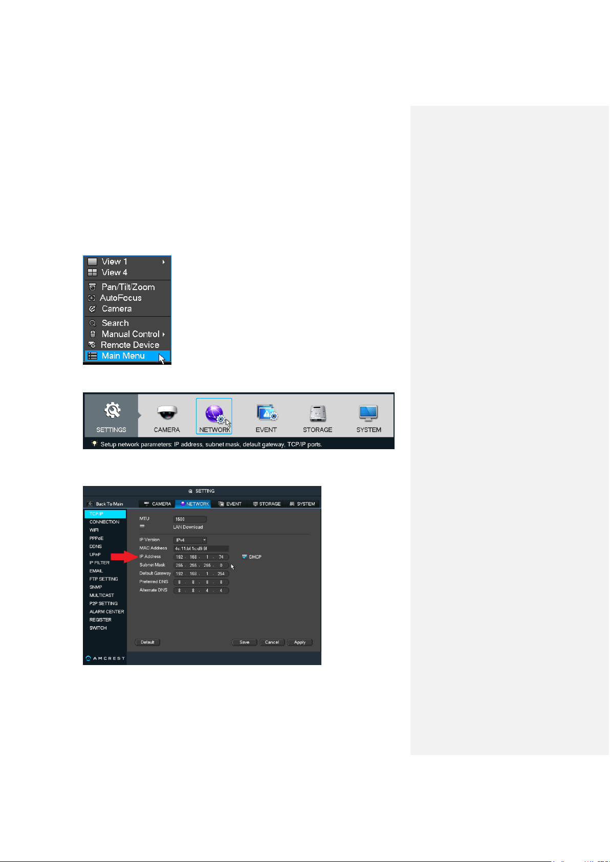
2. Left-click on the main 4-window screen to access the Main Menu, or right-click and
choose it from the list.
3. Click the Network icon, in the third bottom-most row, to the right of Settings.
4. On the NETWORK settings page, you will start on the TCP/IP tab on the left panel list of
options. Locate where it says IP Address on the main center page of the window.
Computer Access Setup Installing the Amcrest browser plugin
41
5. Write it down. It will look something like “192.168.1.74”, although it may vary depending
on your network, router, or service provider.
Note: It does not matter what your IP address looks like. As long as your NVR is connected to
your router with an Ethernet cable, and the DHCP checkbox is checked on the TCP/IP page, the
IP address you write down will be correct.
Installing the Amcrest browser plugin
Once you’ve followed one of the above methods to get to the login screen for the NVR, follow the
below steps to install the browser plugin on Internet Explorer:
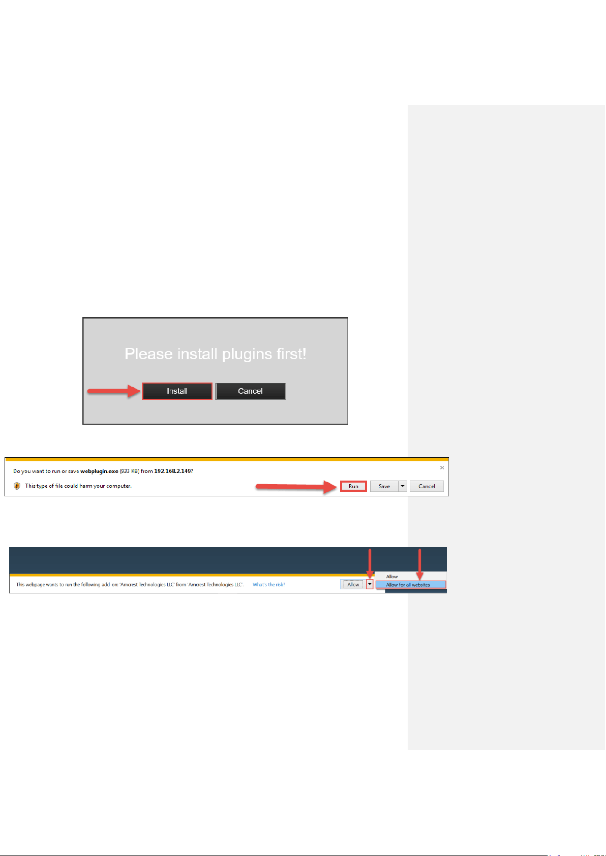
1. On the main login screen, you should see a popup in the center. Click Install.
2. An install button will appear on the bottom of the screen for the plugin: webplugin.exe.
Click Run, then go through the prompts of the install wizard.
3. Once you see the notification along the bottom row. Click the small arrow to the right of
the Allow button, and select Allow for all websites.
Computer Access Setup Setting up NVR Local Access (home or business)
42
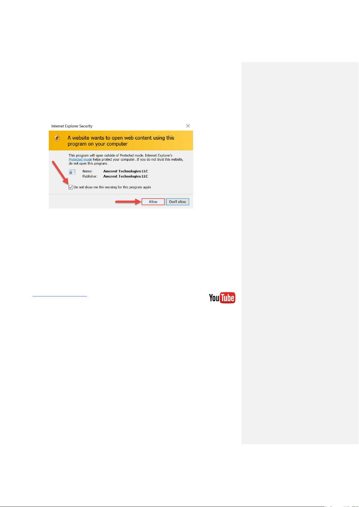
4. If you see a popup window asking you to allow the plugin, mark the checkbox next to “Do
not show me the warning for this program again”, then click Allow.
Setting up NVR Local Access (home or business)
The following procedure can be done one of many ways including: using the Amcrest web
interface (the most common method - that should be followed if this is your first time using this
system), using the RTSP protocol to pull the video feed into a web application (like a custom
website) or standalone program (like VLC media player), or using a CGI command through a
web browser for a direct stream (without the need for a website or program - the NVR’s CGI
commands can be found through the main website - a link to this will be provided in this guide).
For the purposes of this guide, we will cover how to access the NVR through the Amcrest web
interface (the most common method).
To view a video on how to setup the NVR for local access on a computer/laptop go to
http://amcrest.com/videos, click the Videos tab, then find the video titled
“HDCVI - Local Access Setup for PC”.
Note: This is not an HDCVI system, but the same setup process outlined in the
video applies.
Before performing the steps below to gain local access, you will need to make sure the following
items are true:
1. You have your login credentials (if using this local access method as your first, initial
choice to setup your NVR, only items 2 and 3 of this list need to be true)
2. You have located your NVR’s IP address
3. You have installed the Amcrest browser plugin
To find your login credentials, please refer to part 3 of this guide: Console Setup > Logging
in. Otherwise, if this is your first time logging into the NVR and you have skipped Step 3, you will
be able to login with the following username and password:
Username: admin
Password: admin
Computer Access Setup Setting up NVR Remote Access (away from home)
43
Note: After logging in for the first time, you will be prompted to change your password.
To find the NVR’s IP address, please refer to the Amcrest IP Config Software method and the
built-in interface method sections above.
To install the browser plugin for the NVR’s web interface, please refer to the above section:
Installing the Amcrest browser plugin.
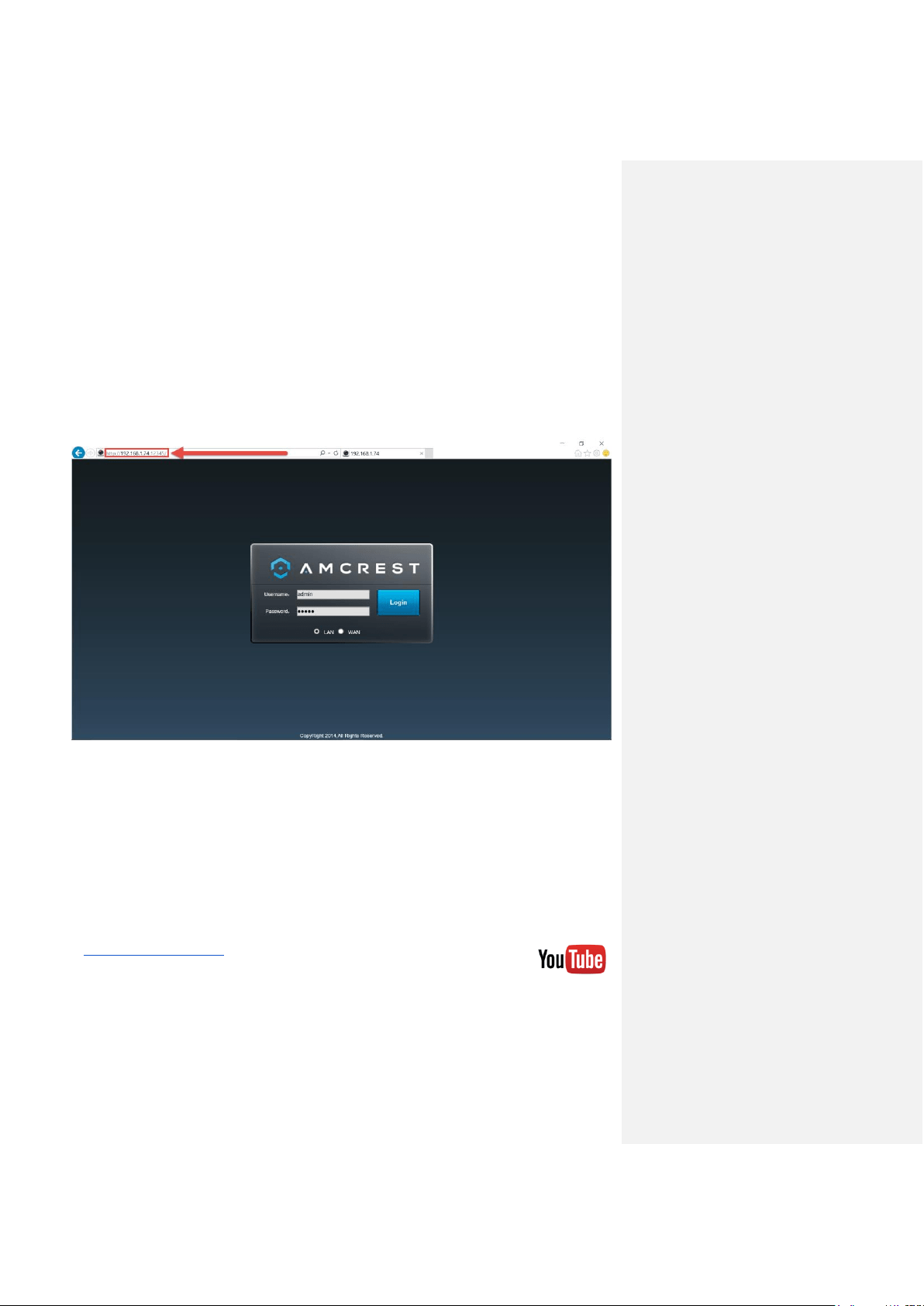
1. Take the IP address and type it into the Internet Explorer search bar, then hit ‘Enter’. It
should look something like “http://192.168.1.74:12345/”
2. Enter your login credentials. You may be prompted to change your password.
3. (Optional) Save this web page as a Favorite for easy access in the future.
Setting up NVR Remote Access (away from home)
For the purposes of this guide, we will outline the most common method for setting up web
access. Using Universal Plug and Play (UPnP) and Dynamic Domain Name Server (DDNS)
functionality is the easiest way to setup stable remote access. For this method, your router
should support the UPnP networking protocol and the protocol should be enabled. Please note
that most common routers will support this feature. Please refer to your router’s manufacturer
documentation to learn how to enable UPnP on your router.
To view a video on how to setup the NVR for UPnP/DDNS remote access go to
http://amcrest.com/videos, click the Videos tab, then find the video titled
“HDCVI - Remote Access Setup for PC (UPnP)”.
Note: This is not an HDCVI system, but the same setup process outlined in the video applies.
Computer Access Setup Setting up NVR Remote Access (away from home)
44
Before performing this setup process, it is recommended that you are familiar with or have
completed the steps in both part 3 ‘Console Setup’ and part 5 of this guide: Computer Access
Setup > Setting up NVR Local Access.
Below is a step-by-step walkthrough that details how to setup the NVR for
remote web access using UPnP and DDNS:
1. Log in to your NVR’s built-in (console) interface, open the Main Menu (by left-clicking
once, or right-clicking and choosing MAIN MENU from the dropdown, then click
NETWORK from the SETTINGS row:
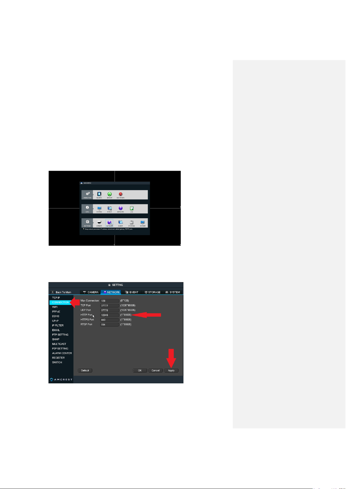
2. From the left hand navigation panel, click CONNECTION, then locate the HTTP port on
the right. It is recommended to ensure the port number is at least 5 digits long to prevent
any port conflicts. You can change the port to any 5 digit number that is less than 65535
(e.g. 12345) by clicking the number field, and entering a new port number. Write it down,
then click Apply.
Computer Access Setup Setting up NVR Remote Access (away from home)
45
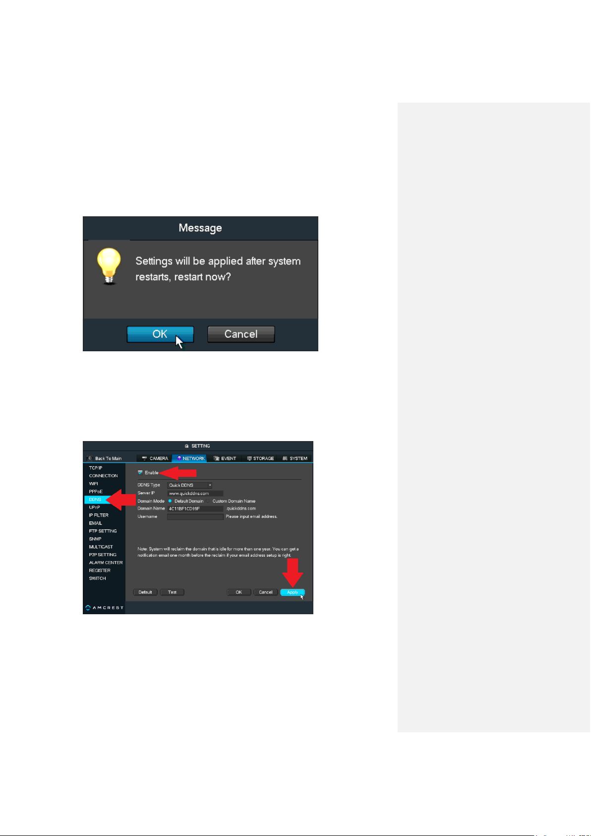
3. The system will need to reboot for this change to take effect. Click OK.
4. Once rebooted, login to your NVR again, open the MAIN MENU, then click NETWORK
under SETTINGS again.
5. Click CONNECTION from the left navigation panel again, and ensure that the HTTP port
has changed.
6. Next, click DDNS from the left navigation panel, check the Enable checkbox, then click
Apply on the bottom-right.
7. Write down the entire Domain Name field, including the white text that says:
.quickddns.com
Computer Access Setup Setting up NVR Remote Access (away from home)
46
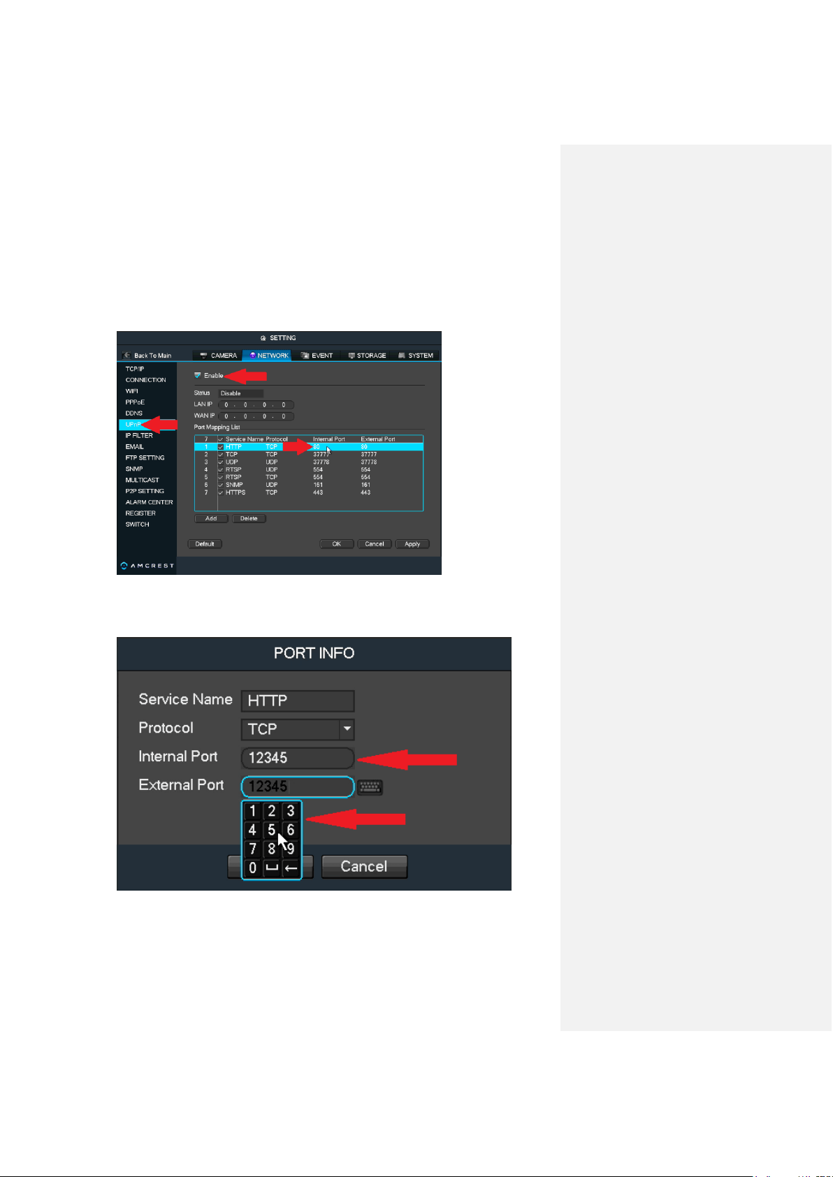
8. Click UPnP from the left navigation panel, and check the Enable checkbox at the top.
Then, locate row 1 in the Port Mapping List, where HTTP is written beneath Service
Name, and double-click the numbers in the field just below Internal Port to change the
HTTP port numbers.
9. In the PORT INFO window that appears, click into the number fields next to Internal Port
and External Port to change them to the same port number that was chosen in step 2
above (e.g. 12345). Then click OK.

Computer Access Setup Setting up NVR Remote Access (away from home)
47
10. Once back to the previous UPnP page, uncheck the last 4 checkboxes in the Port
Mapping List: row 4, row 5, row 6, and row 7.
11. Now, click Apply, and ensure it says ‘Searching now’ in the field next to Status.
12. Exit this menu to go back to the main menu, then re-enter the UPnP menu, and ensure
the UPnP status says ‘Success’.
Note: If this does not say ‘Success’, try resetting the NVR, then your router. If it still does
not work, it may be because your router does not support UPnP. In this case, you will
need to port forward to gain remote access. Please read step 5: Check for UPnP
below, in the troubleshooting steps that follow this guide for more information on what
to do next.
13. Open a web browser and enter in the DDNS domain name address from step 7, enter in
a colon “:” (without quotes), then type the port number from step 2 onto the end.
a. For example, if the DDNS domain name is http://abc123456789.quickddns.com
and your HTTP Port is 12345, the URL would be
http://abc123456789.quickddns.com:12345
14. The browser may prompt you to install a plugin. Click install to download the plugin, then
click on the plugin installation file to install the plugin. (For help installing the plugin, refer
to part 5 of this guide: Computer Access Setup > Installing the Amcrest browser
plugin.)
15. Enter your login credentials into the username and password fields.
16. Click the WAN option, and then click Login.
Computer Access Setup Remote access not working? (troubleshooting steps)
48
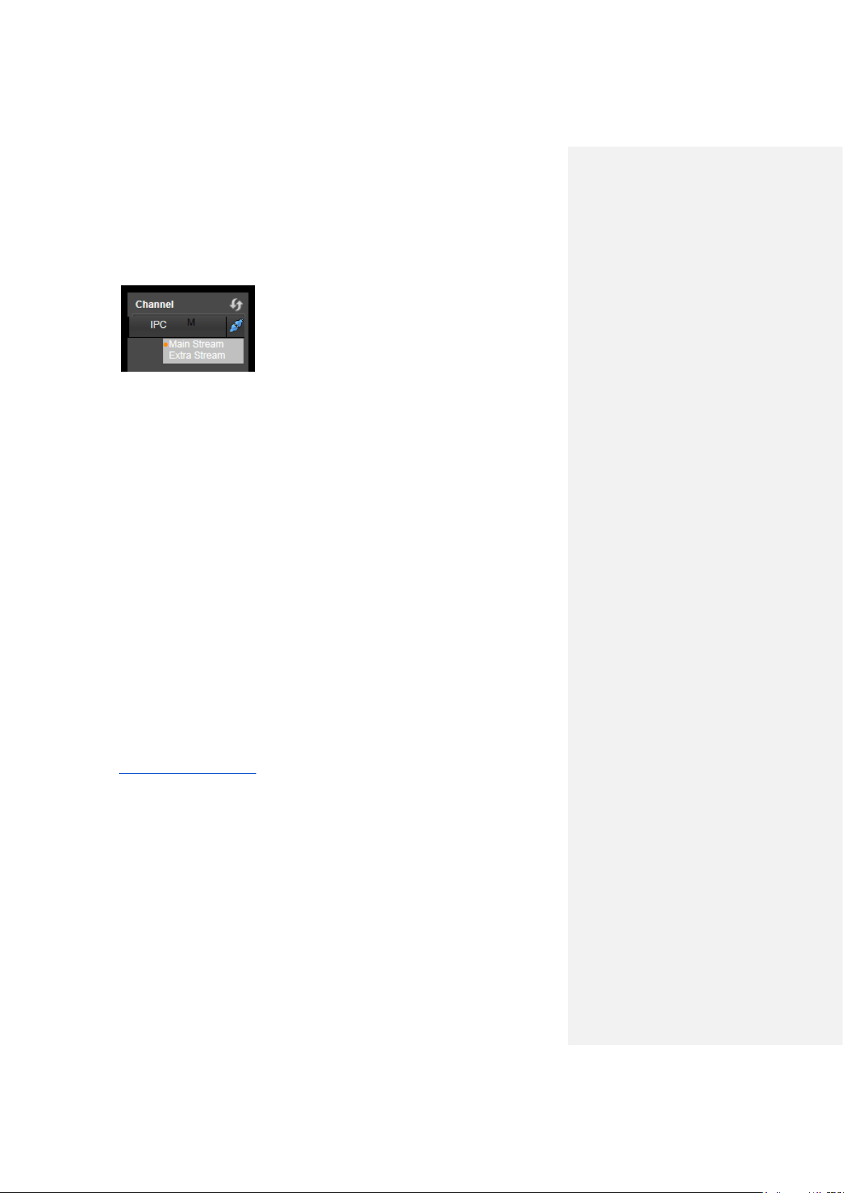
17. Once the main interface opens, click the plug icons next to each camera in the left panel.
After clicking the plug icon, you can choose between Main Stream and Extra Stream.
Main Stream is HD and takes more bandwidth (requires faster network speed).
Extra Stream is SD and requires less bandwidth (can work on slower internet
connections).
To get more detailed information on other methods to set up remote web access for the Amcrest
NVR, please refer to the user manual.
Remote access not working? (troubleshooting steps)
1. Re-enter login credentials: Confirm that your username and password for accessing
the NVR are correct. Please refer to part 3 of this guide: Console Setup > Logging in.
The same credentials you use to log in to the console in that section are what you will
enter into the login screen on the web interface.
2. Use the correct web browser: Make sure you are using Internet Explorer as your web
browser.
3. Confirm plugin is installed: If you still see any popup windows when trying to log in to
the web interface, please make sure you have correctly installed the Amcrest browser
plugin: webplugin.exe. Please refer to part 5 of this guide: Computer Access Setup>
Installing the Amcrest browser plugin.
4. Write the URL correctly: When using Internet Explorer, it is crucial to write the NVR’s
remote access URL correctly. Some versions of Internet Explorer will not automatically
include the “http://” prefix to the beginning of an IP address that is typed in. Check your
search bar and, if you do not see “http://” before your URL (e.g. 192.168.2.149:12345),
please add it. In addition to that, make sure that you are using a colon “:” and not a
semicolon “;”. Your final URL should look something like this:
“http://192.168.2.149:12345/” (without quotes). Keep in mind that the IP address and port
number will be different depending on your setup.
5. Select WAN button: The LAN radio button will be selected by default. You must click
and select WAN in order for this remote connection to work.
6. Connect to the internet: Confirm that your computer is properly connected to the
internet by loading another web page first, then trying the NVR’s remote access URL
again. Also, confirm that an Ethernet cable is connected from your router to the correct
port on the back of your NVR. If using a PoE NVR, it will NOT be one of the 4 or 8 PoE
ports bunched together. It will be a standalone internet port. Please refer to part 2 of this
guide: Front/Back Panel Diagrams & Descriptions.

Computer Access Setup Remote access not working? (troubleshooting steps)
49
7. Check for UPnP: In order for remote access to work, UPnP has to be enabled on your
NVR and it has to be enabled and supported on your router. Check your router’s
documentation to confirm whether UPnP is supported. Otherwise, an alternative to UPnP
is port forwarding which can be done by following a video tutorial for the HDCVI system.
To find this video, go to http://www.amcrest.com/videos/ and find the video by clicking
Playlists (tab) > Amcrest - 1080P & 720P HDCVI DVR > HDCVI - Remote Access
Setup for PC (Port Forwarding).
Note: This is NOT an ‘HDCVI’ system, it is an NVR. However, the same exact procedure
as shown in the video applies.
8. Still not working?
Please contact Amcrest Support via one of the following options:
● Visit http://amcrest.com/contacts and use the email form
● Call Amcrest Support using one of the following numbers
Toll Free: (888) 212-7538
International Callers (Outside of US): +1-713-893-8956
USA: 713-893-8956
Canada: 437-888-0177
UK: 203-769-2757
● Email Amcrest Customer Support support@amcrest.com
Computer Access Setup Web Interface Walkthrough
48
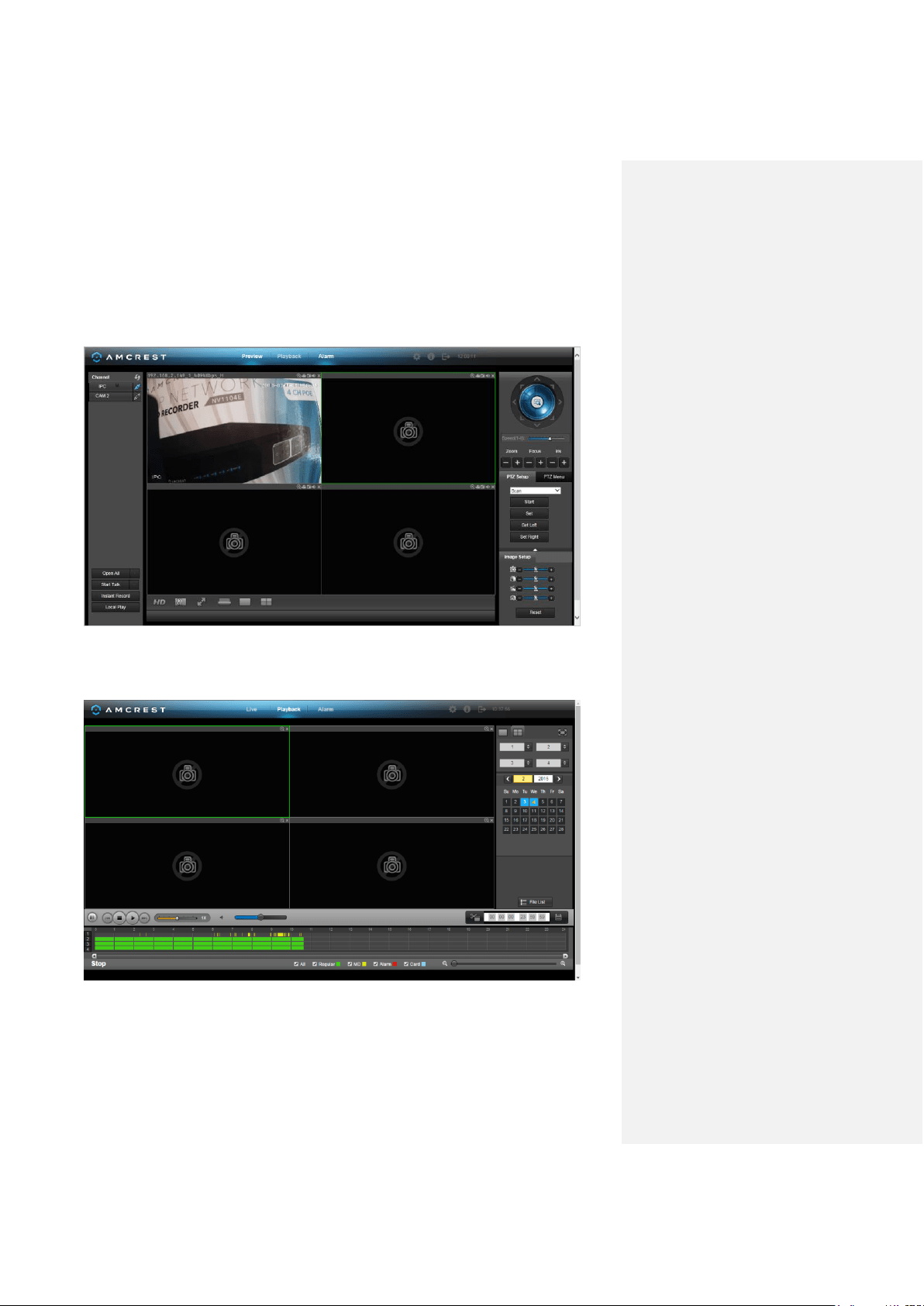
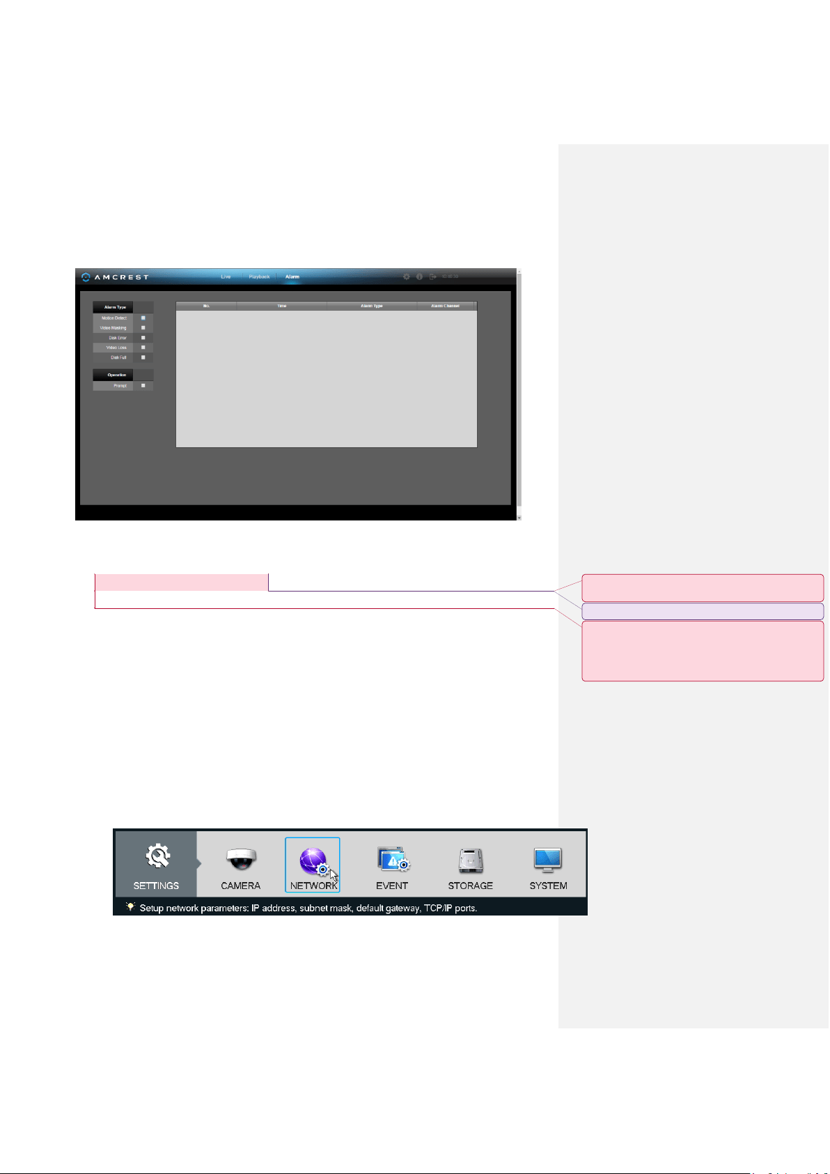
Web Interface Walkthrough
The web interface has 3 main tabs:
Live: This tab shows live playback of any connected cameras. Ensure that the small icon on the
right of each camera’s name on the left hand list is blue; otherwise the live video feed will not
show. You can also control PTZ and image settings here, as well as view cameras in full screen.
Playback: This tab allows for playback of recorded video. Select the date from the menu on the
right and then click on the timeline at the bottom of the screen to select a playback starting
location. Once the starting point has been selected, hit the play button to begin playback.
Amcrest View App Setup Enabling P2P on the NVR
49
Alarm: This tab shows a list of any alarms that have been triggered, either by motion detection,
video masking, disk error, video loss, or the disk becoming full.
6. Amcrest View App Setup
The Amcrest View app grants instant access to all live camera streams from any location. This is
the primary application most users prefer when using Amcrest systems. The app supports a
multitude of features and includes both a plug-and-play setup as well as a manual network setup.
For purposes of this guide, we will use Amcrest View Pro, which is free on both the App Store
and Play Store.
Before the NVR can be accessed through the app using the easy plug-and-play method (P2P
Setup), P2P must be enabled on the NVR.
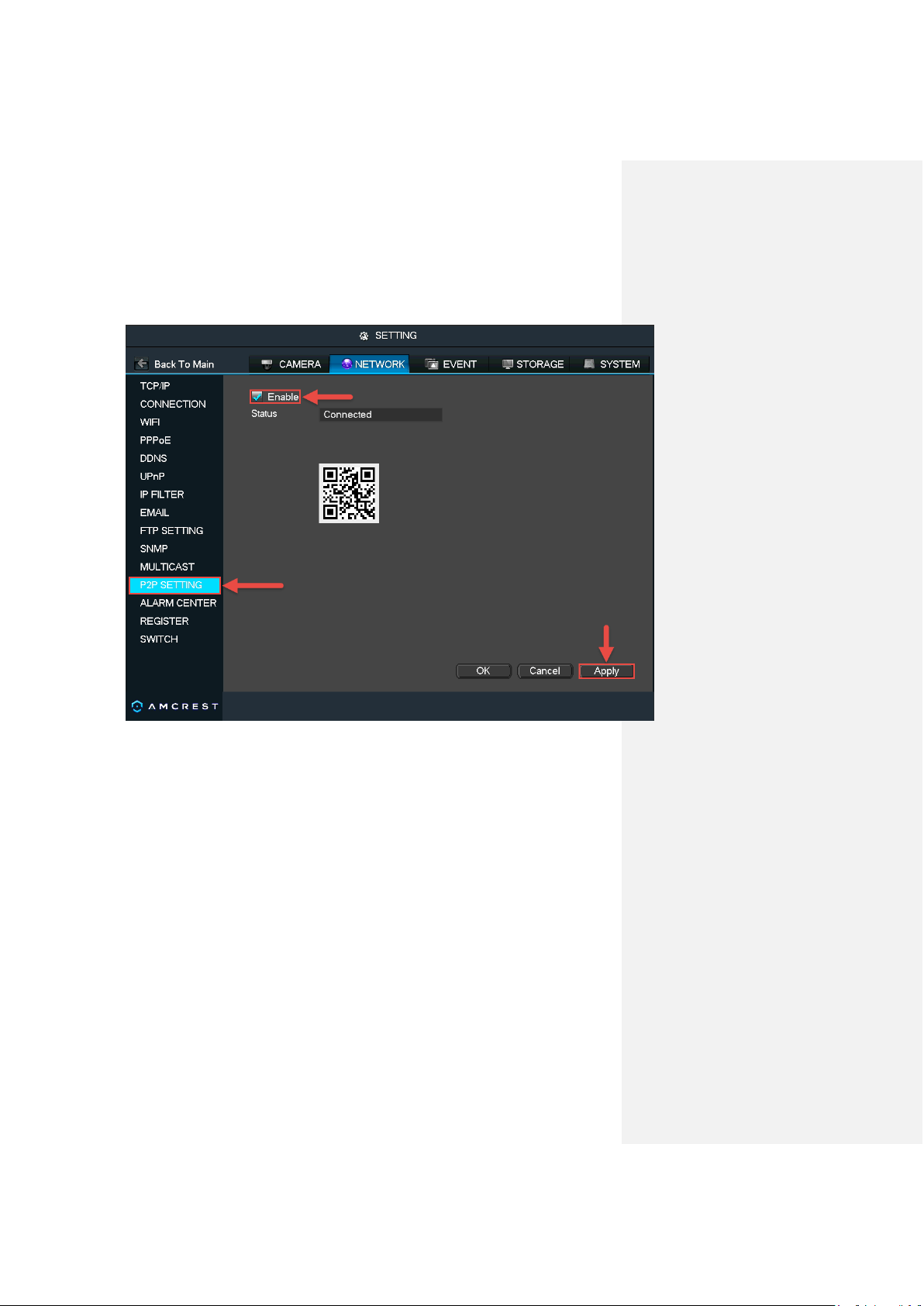
Enabling P2P on the NVR
1. Log into your NVR console’s built-in interface using the NVR login credentials. Please
refer to part 3 of this guide: Console Setup > Logging in.
2. Open the MAIN MENU by left-clicking the NVR’s home preview screen. Then, click
NETWORK in the bottom SETTINGS row:
Commented [1]: The app has changed majorly, so
please update this and the following section.
Commented [2]: _Marked as resolved_
Commented [3]: _Re-opened_
I can provide you the APK for the revised app so you
have an understanding of how it's gonna work, cause
the setup process is gonna change drastically. About to
email you mockup files as well.
Amcrest View App Setup Enabling P2P on the NVR
50
3. Select P2P SETTING from the left navigation panel’s list of pages. Mark the checkbox
next to Enable, then click Apply and OK.
4. Exit out of the main menu, then come back to the P2P SETTING page and confirm that the
Status is ‘Connected’.
Amcrest View App Setup Amcrest View Pro Setup
51
Amcrest View Pro Setup
The following steps will continue the app setup process for an Android phone and, though the
iPhone version of the app has slightly different steps, most of this process is identical and easy.
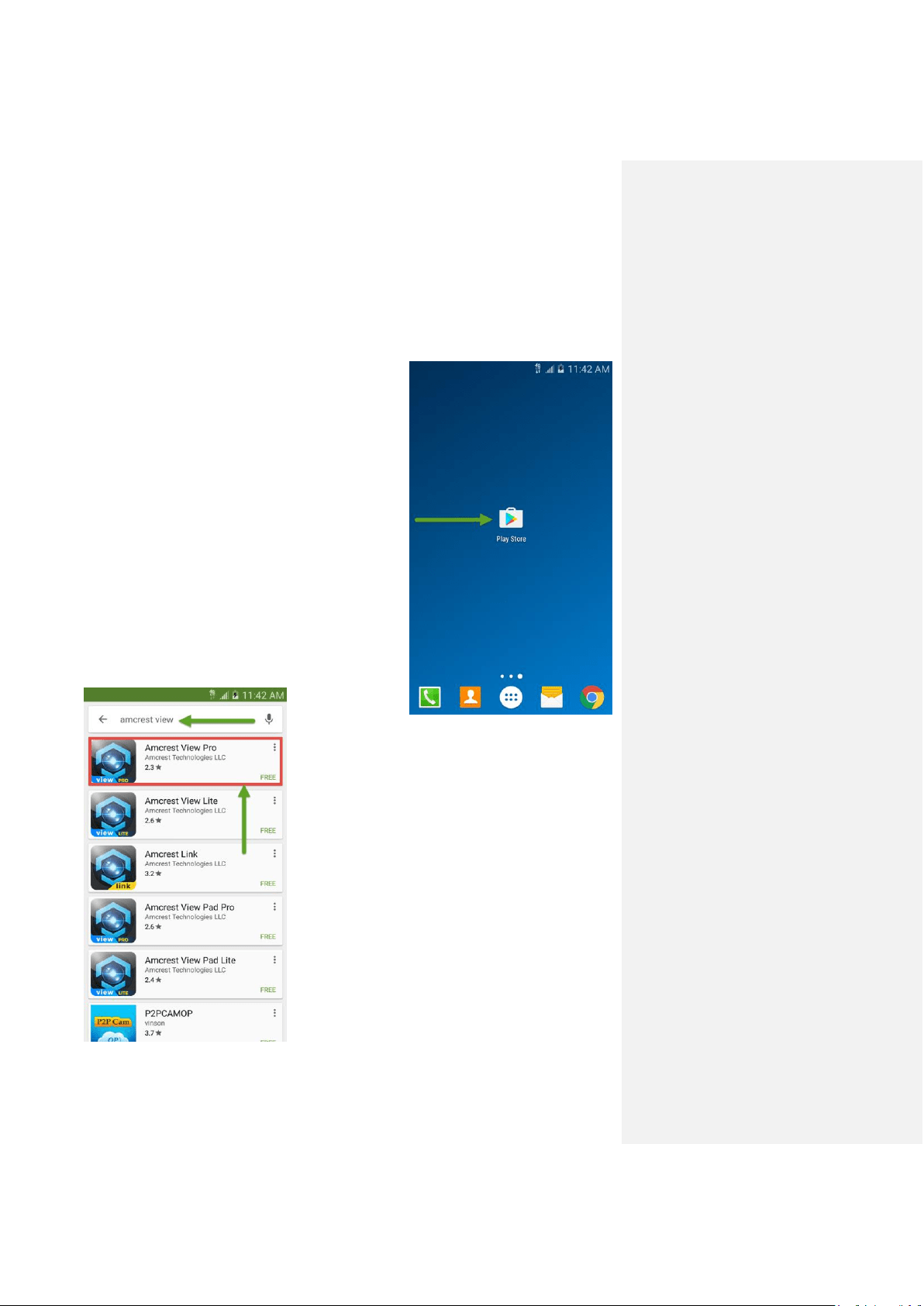
1. On your Android device,
locate and open the Play
Store.
2. Type “Amcrest View” in the search bar,
hit enter, then tap Amcrest View Pro.
Amcrest View App Setup Amcrest View Pro Setup
52
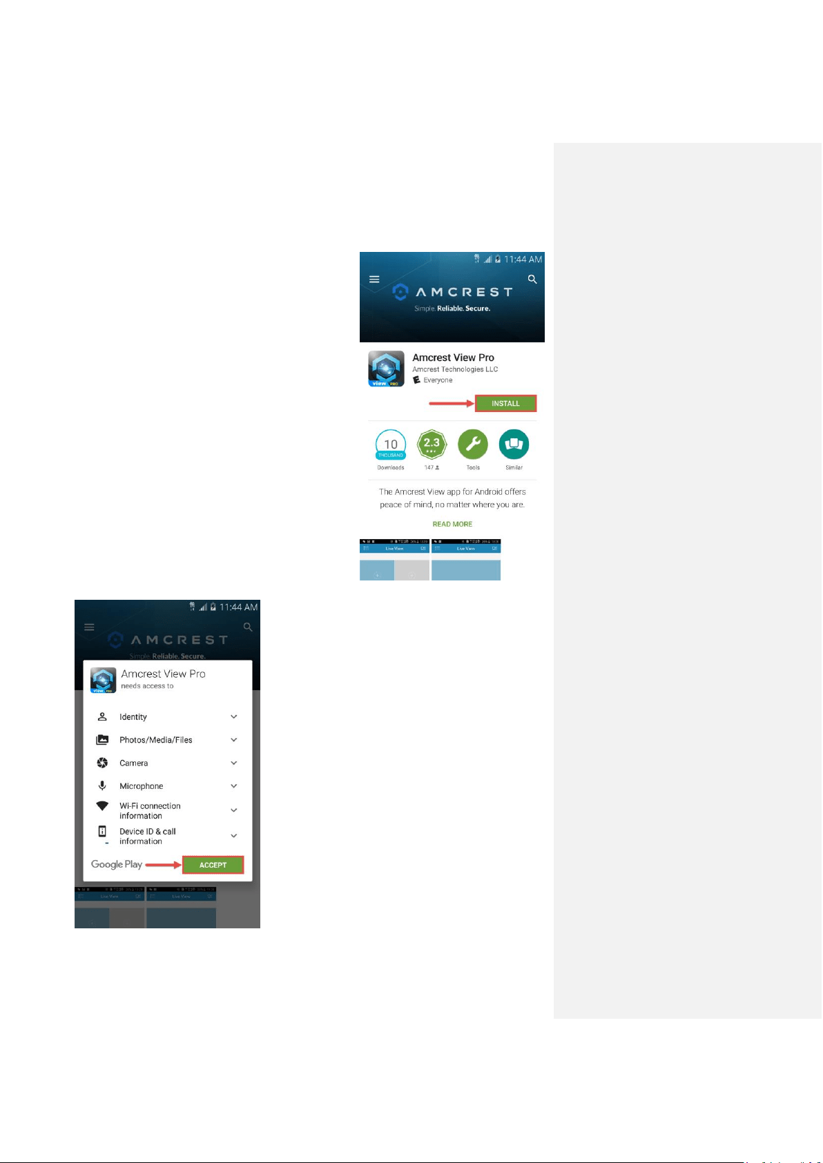
3. Tap Install to begin installation.
4. Tap Accept on the next screen.
Amcrest View App Setup Amcrest View Pro Setup
53
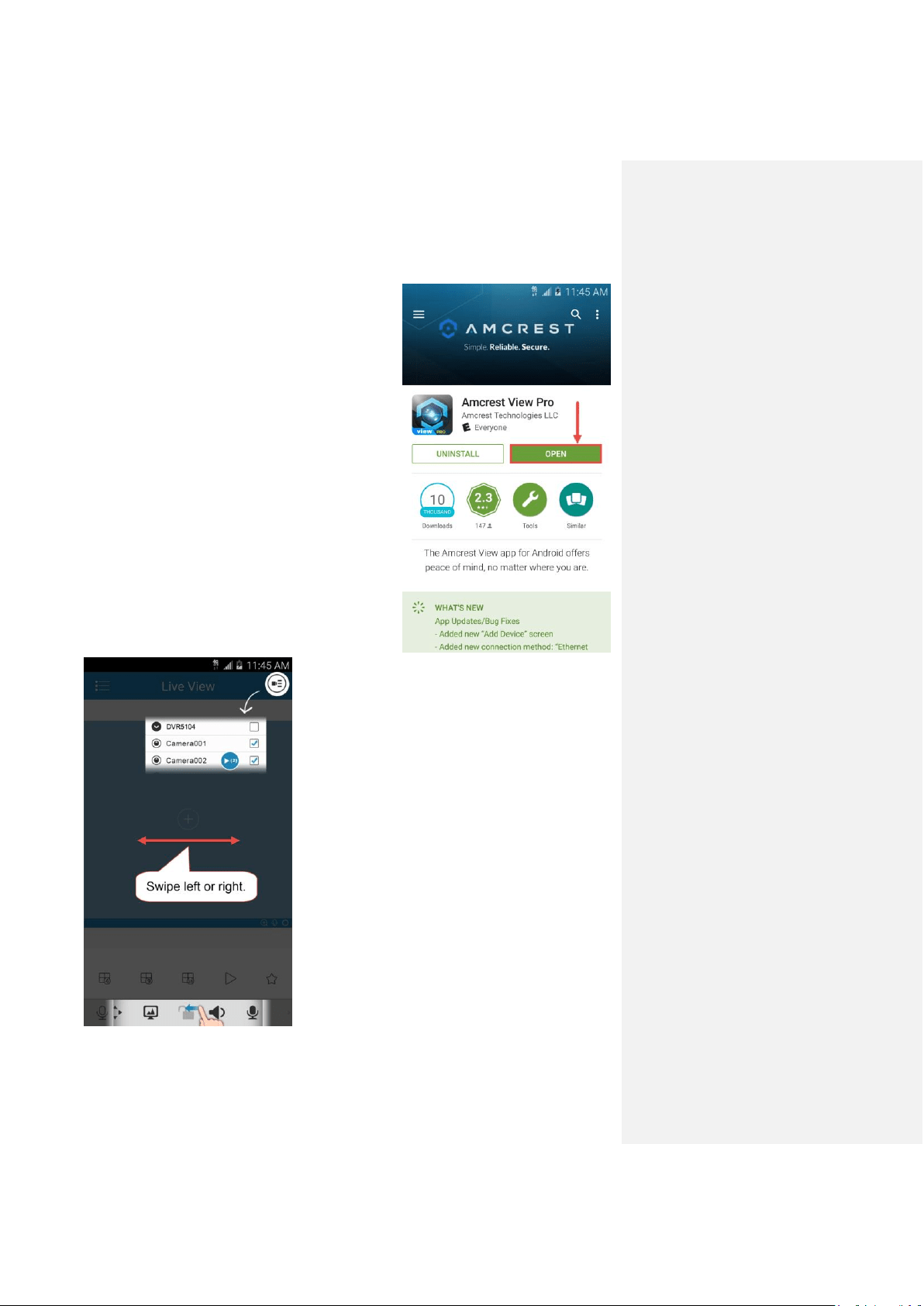
5. When finished installing, tap Open to launch the
app. You will see some screens appear.
6. When it shows the screens with arrows, you can
swipe them out of the way.
Amcrest View App Setup Amcrest View Pro Setup
54
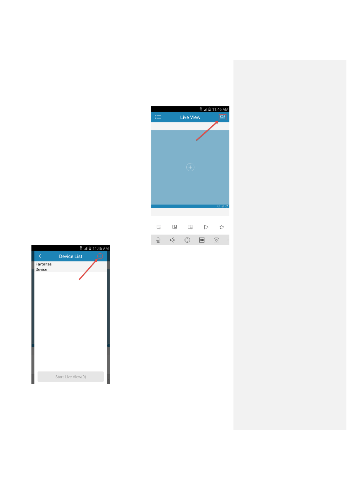
7. Now you should see the home screen of your
app. Tap the icon in the top-right to get to the
Device List.
8. Tap the + icon in the top right of this window to get
to the Connection Type screen.
Amcrest View App Setup Amcrest View Pro Setup
55
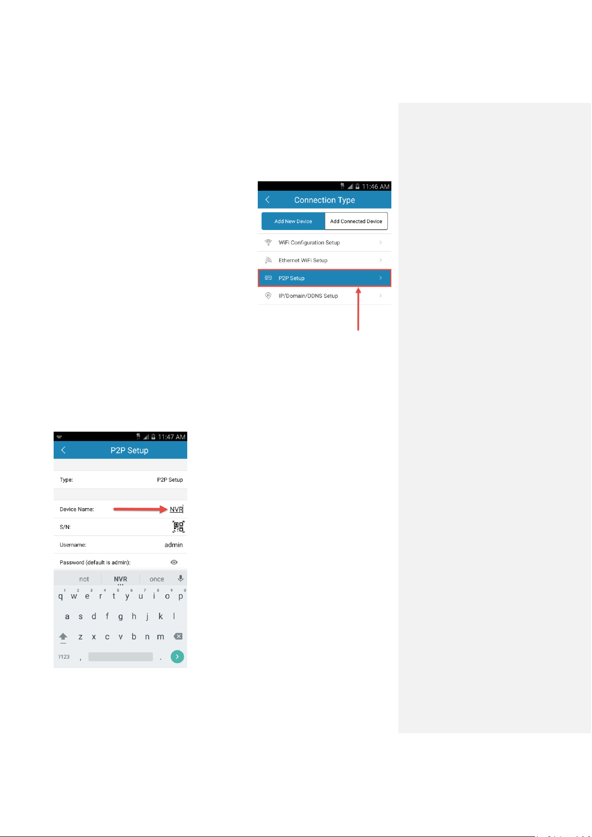
9. Select P2P Setup from the list to get to the P2P
Setup main page.
10. Name your device (this can be any name you
want).
Amcrest View App Setup Amcrest View Pro Setup
56
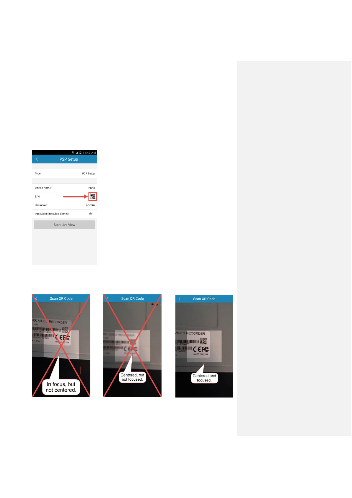
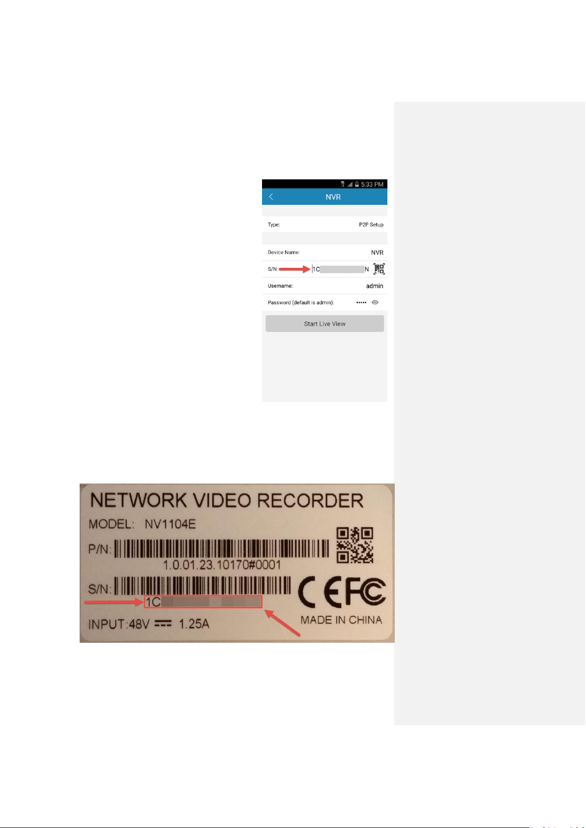
11. Next, we need to input the NVR's serial number. You can either scan the QR code or
enter the serial number manually.
QR scan (recommended method - easier):
Tap the QR code icon in the far right of the S/N field, and it will activate your
smartphone's camera:
Note: the QR code will only scan if positioned entirely inside the
clear square in the center of the screen. Once centered, if the
QR code still appears blurry, move your smartphone back and
forth slowly until the image comes into focus.
Try to center and focus the QR code as shown below, to the right.
Amcrest View App Setup Amcrest View Pro Setup
57
As soon as the QR code is read, your phone will
vibrate and the app will automatically take you
back to the P2P Setup page where you will notice
that the serial number has been automatically
populated in the S/N field:
Entering serial number manually (technical method - harder):
In order to locate your serial number, you must either have physical access to the NVR or
computer access to the web interface.
On the bottom of the NVR console, there is a sticker with the serial number printed on it.
It will begin with '1C'. Write this down.
Then enter this into the S/N field of the P2P Setup screen of your app.
Amcrest View App Setup Amcrest View Pro Setup
58
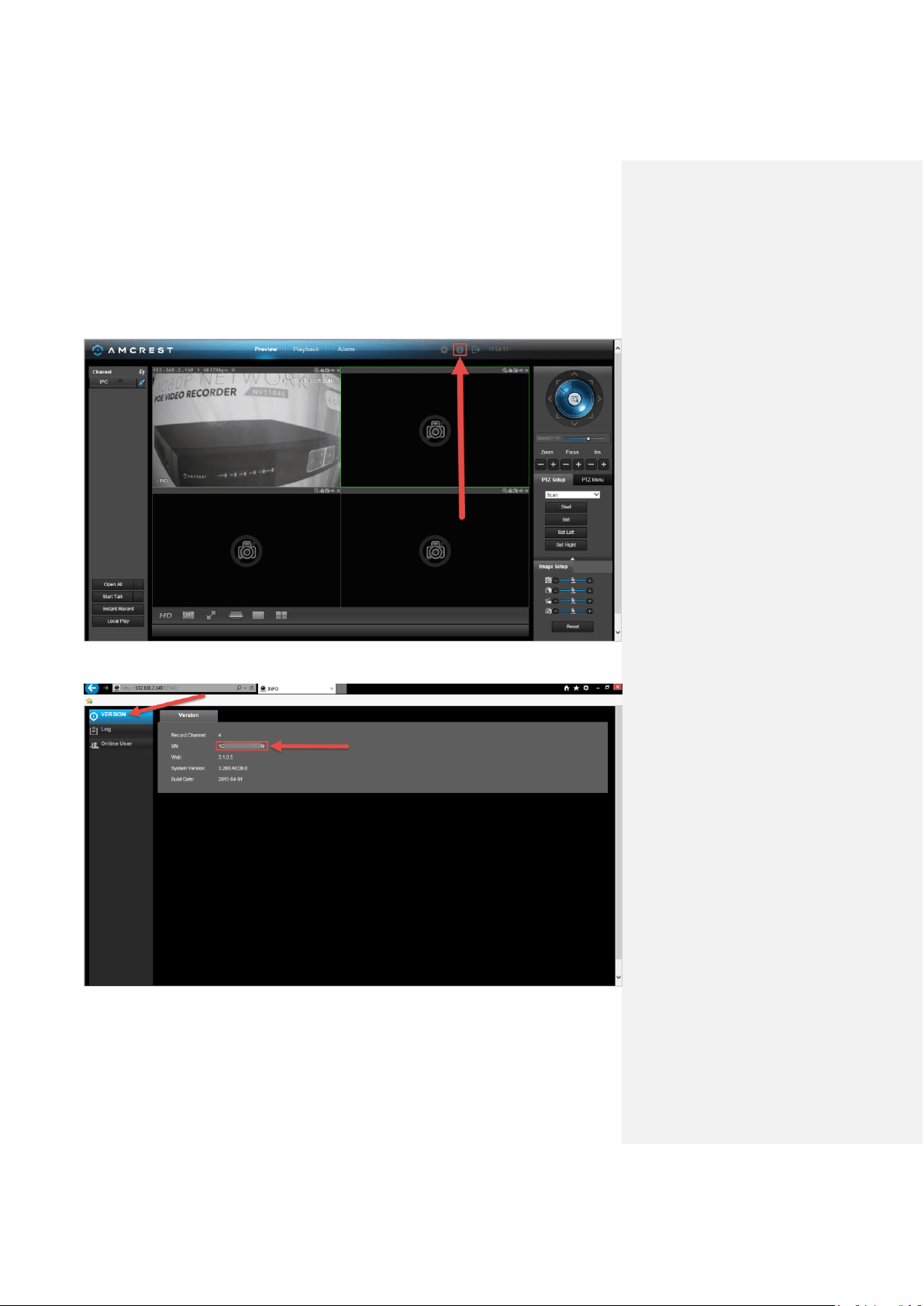
Otherwise, if you are setting up the app after gaining local access with a computer, log
into the web interface with your username and password. Then, click the 'i' button in the
top-right of the screen:
Make sure you are on the ‘VERSION’ tab, and you will see the serial number written there:
Write it down, then enter it into the S/N field of the P2P Setup Screen of your app.
Amcrest View App Setup Amcrest View Pro Setup
59
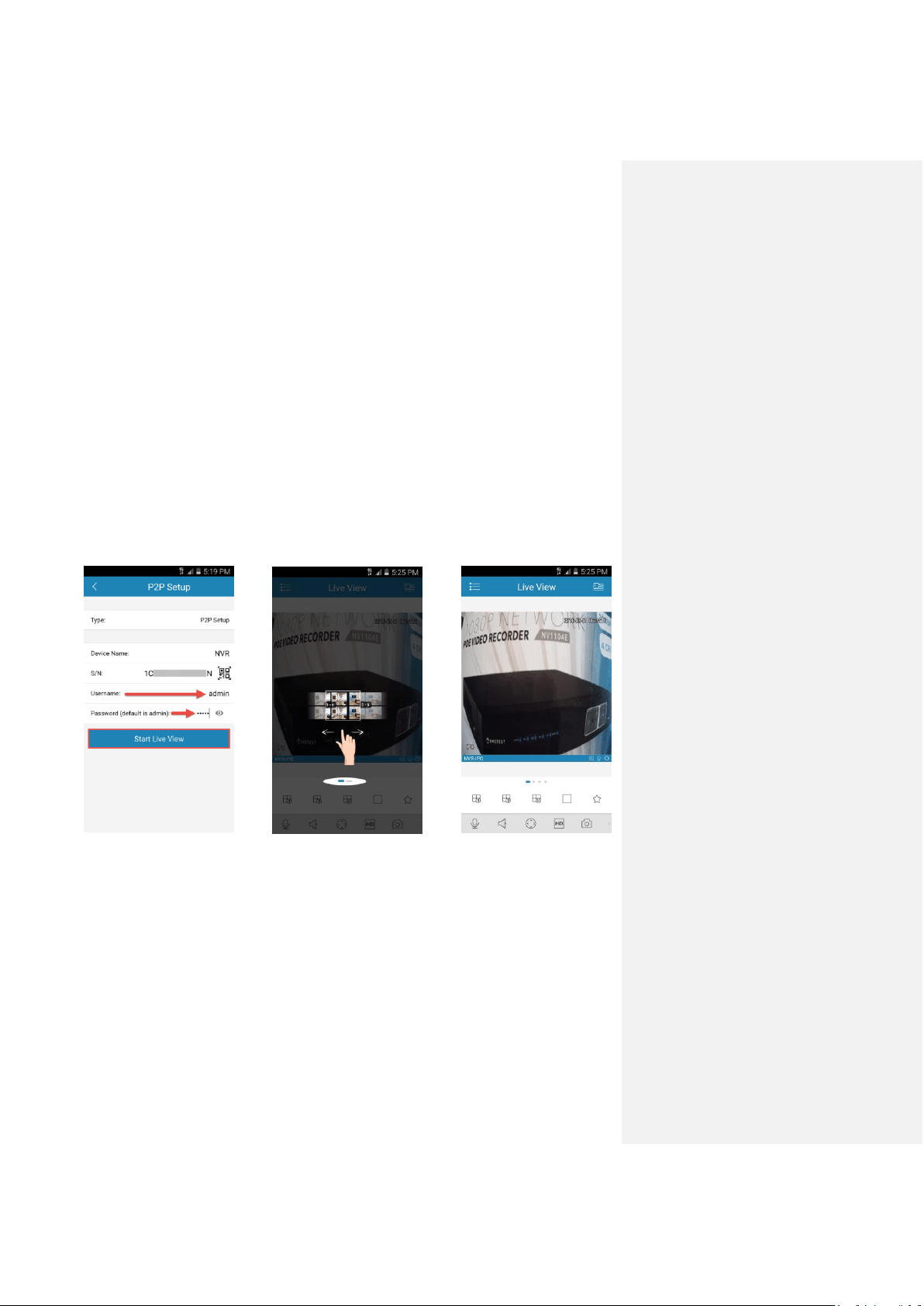
12. Return to your app’s P2P Setup page, and enter your username and password. These
are the same credentials used to access the console’s built-in interface directly. Refer to
part 3 of this guide: Console Setup > Logging in.
If you skipped that step, or this is your first time accessing the NVR, the default
username “admin” and password “admin” will work and you will be prompted to change
your password.
Note: You may not see any cameras if this is your first setup method, even though you
will have setup the NVR to the app successfully. Refer to part 3 of this guide: Console
Setup > Adding cameras.
After entering your Username and Password, tap Start Live View to connect to your
NVR.
There will be one instructional screen that appears, you can swipe this out of the way
before beginning to view the live streams from your connected cameras.

Amcrest View App Setup App setup not working? (troubleshooting steps)
60
App setup not working? (troubleshooting steps)
1. Re-enter login credentials: Are you getting a (quote ‘incorrect password’ error)
message? Try double checking your username and password. These will be the same
credentials used to log into the NVR console’s built-in interface.
2. Confirm your phone is online: Make sure that your phone is receiving a strong WiFi or
cellular data signal. Confirm the Internet connection is working by loading a webpage or
testing another internet enabled app.
3. Confirm the NVR is online: Make sure an Ethernet cable is connected from your router
to the Internet port on the back panel of your NVR console. (For help with this, refer to
part 2 of this guide: Hardware Setup > Setting up the cable connectons.)
4. Confirm P2P is enabled: In order to use the P2P Setup to gain plug-and-play instant
access, P2P needs to be enabled on the NVR. It will be enabled by default. To confirm
P2P is enabled, log into the main console built-in interface for your NVR and select
Network from the Main Menu (in the Settings row). Then, click P2P from the left
navigation panel (on the bottom). Make sure the checkbox is checked next to “Enabled”.
If it is not, check it, click Apply down below, then attempt the P2P App Setup again (tap
Start Live Preview).
5. Confirm the serial number: if you entered the serial number manually, double check
that it is correct and re-enter it. This does not apply if you used the QR code scan.
6. Still not working?
If you have tried all of the above troubleshooting steps, try rebooting your NVR. Then,
restart your phone and try the P2P Setup on your app again. Contact support if you are
still unable to gain access.
To view a video on how to setup the Amcrest NVR for remote access on a smartphone
or tablet, go to http://amcrest.com/videos and view the video titled
“How to Setup Amcrest HDCVI NVR for Remote Access on Smartphone/Tablet”.
Note: This is not an HDCVI system, but the same setup process outlined in the video applies.
Amcrest View App Setup Amcrest View Pro interface overview
61
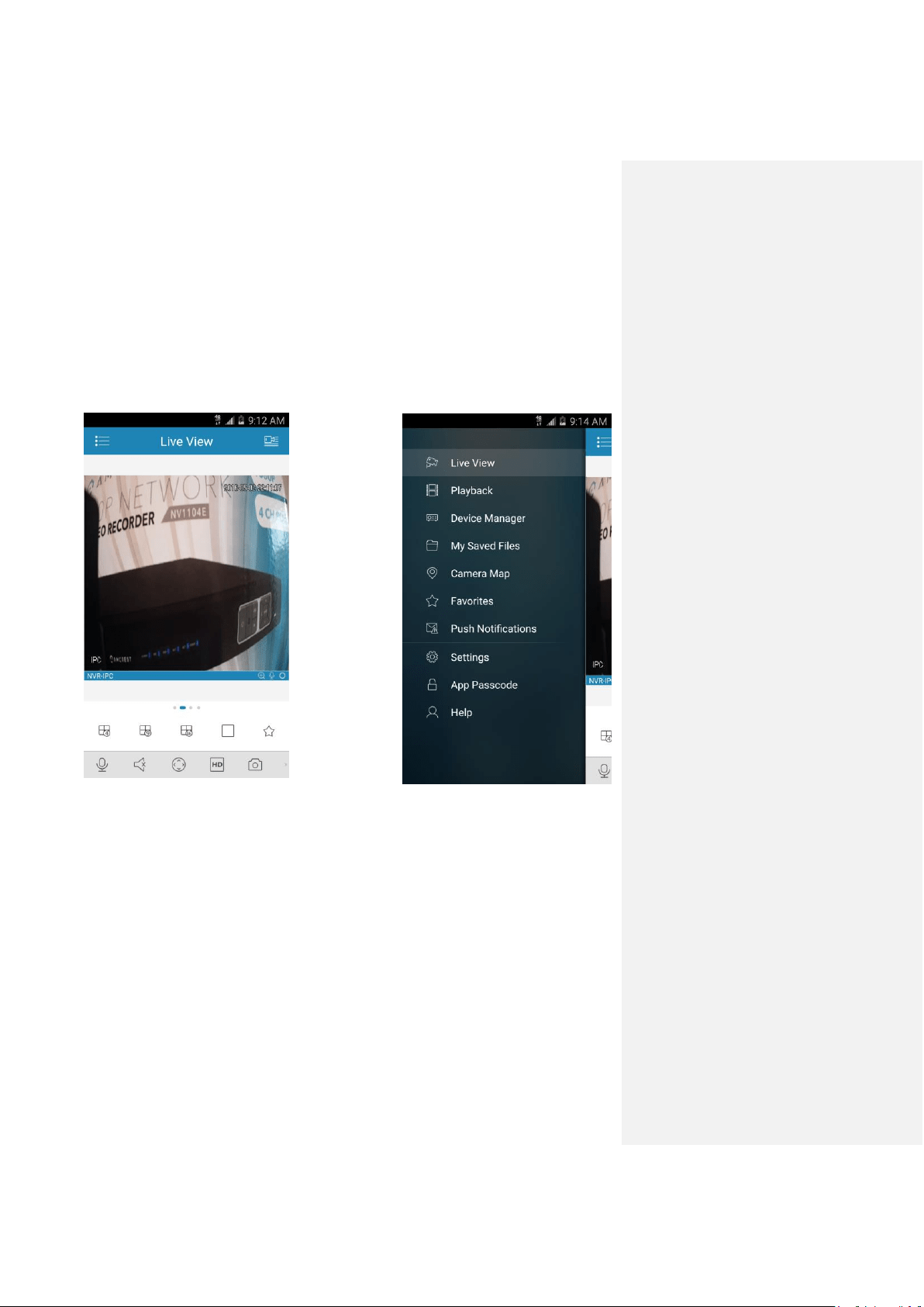
Amcrest View Pro interface overview
Once the app is setup to work with your NVR, it should look like the image below on the left.
Here, you will be able to access all crucial functions like taking snapshots, manual recordings,
etc.
Clicking the Menu Icon on the top left hand corner will open the menu for this app, and it should
look like the image below on the right.
Live Preview is the default screen that the app opens on, but from the menu, Playback, and
Device Manager can be opened, as well as other menu items for other features.
Note: For help identifying and understanding app features, either tap the icon to see a tooltip
description, or open the main menu, then tap Help to learn more.
Amcrest View Web Portal Setup Installing the AmcrestView.com browser plugin
62
7. Amcrest View Web Portal Setup
You can access your NVR through a computer using the P2P web portal AmcrestView.com for
quick plug-and-play access. It uses the same technology as the Amcrest View mobile app and is
an easy, non-technical setup method.
There are 2 methods of accessing your NVR using AmcrestView.com: the user method
(registering an account for login), and the device method (instant direct access using the serial
number).
Both of these methods require that the Amcrest browser plugin be installed for
AmcrestView.com.
Installing the AmcrestView.com browser plugin
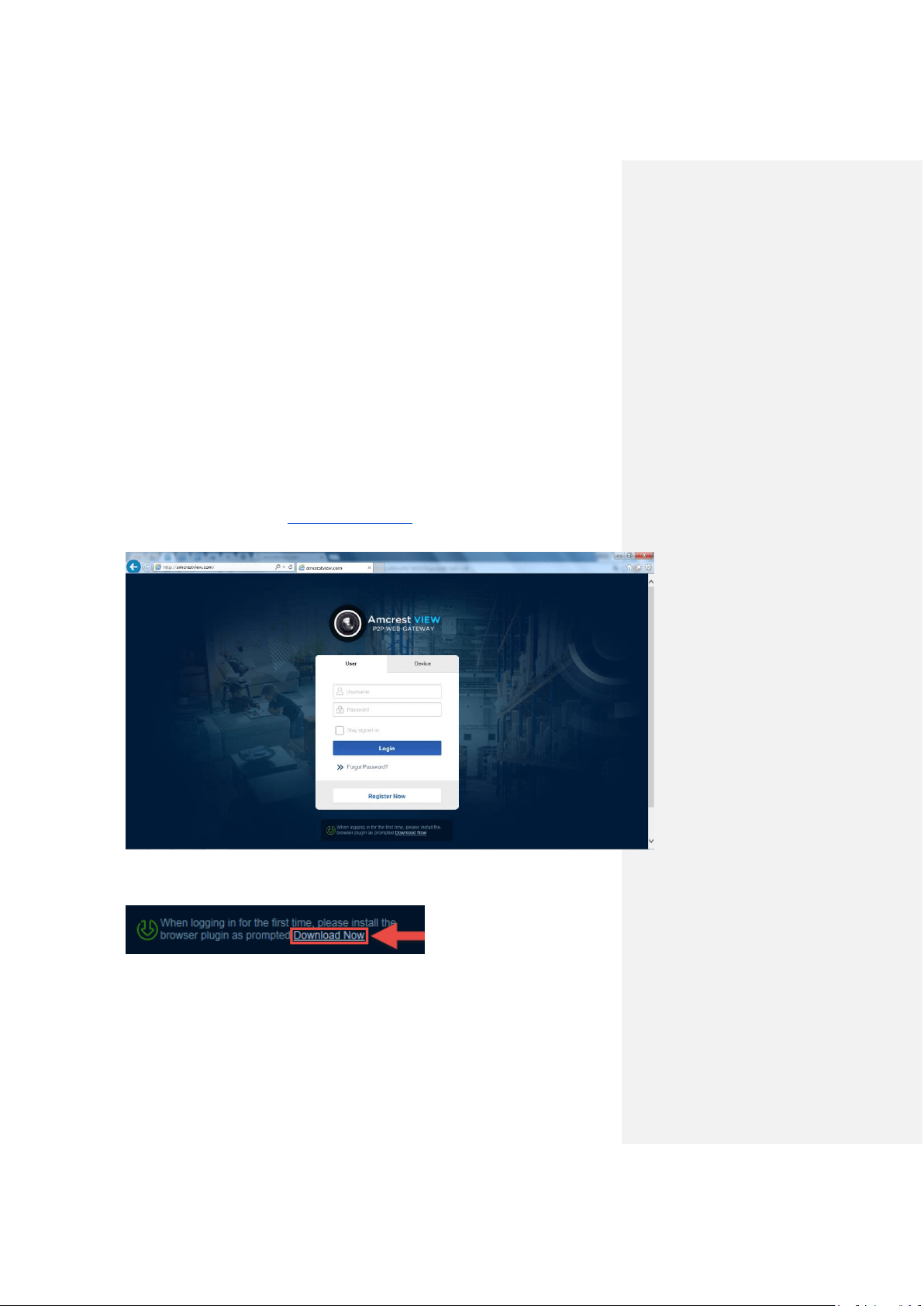
1. Open Internet Explorer, type ”www.amcrestview.com” into the search bar, and hit Enter.
This will take you to the login screen:
2. Once you’re on the login page, you will see a message about installing the plugin below
the login box. Click Download Now:
Amcrest View Web Portal Setup Installing the AmcrestView.com browser plugin
63
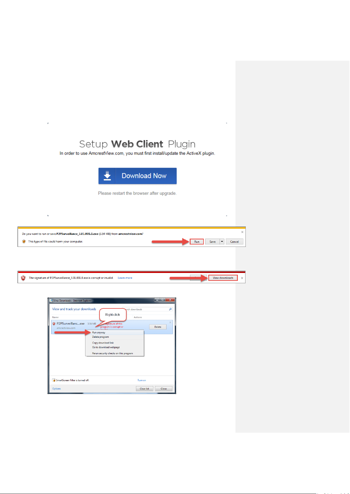
3. This will take you to another page where you will need to click the Download Now
button:
4. You will be prompted by the browser to install the plugin. Click Run:
5. You may be prompted to verify this download. This software is not harmful to your
computer and will not make any unwanted changes. To verify, start by clicking View
Downloads:
6. In the View Downloads page, right click the plugin, then click Run Anyway.
Amcrest View Web Portal Setup Installing the AmcrestView.com browser plugin
64
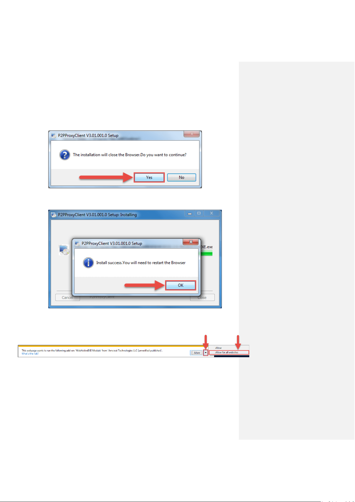
7. The plugin will close your browser sessions to install. Save any pages, then click Yes:
8. On the next prompt, it will say the install was successful and ask you to restart your
browser. Click OK:
9. You will be taken back to the login page and see another notification from your browser
asking you to allow this plugin on this web page. Click the small arrow next to Allow,
then click Allow for all websites:
Amcrest View Web Portal Setup User method
65
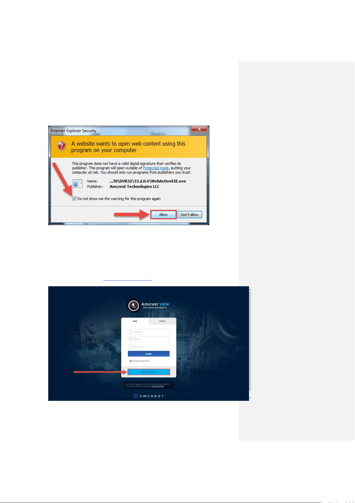
10. Another popup will appear asking you to allow this plugin. Mark the checkbox next to Do
not show me the warning for this program again, then click Allow:
Now the plugin has been installed successfully and you can continue on to register for an
account for NVR access through AmcrestView.com
User method
The user method requires that you first install the Amcrest browser plugin for AmcrestView.com.
Then, you can register for an account to set up your NVR.
1. On the main login screen, www.amcrestview.com, click the Register Now button:
Amcrest View Web Portal Setup User method
66
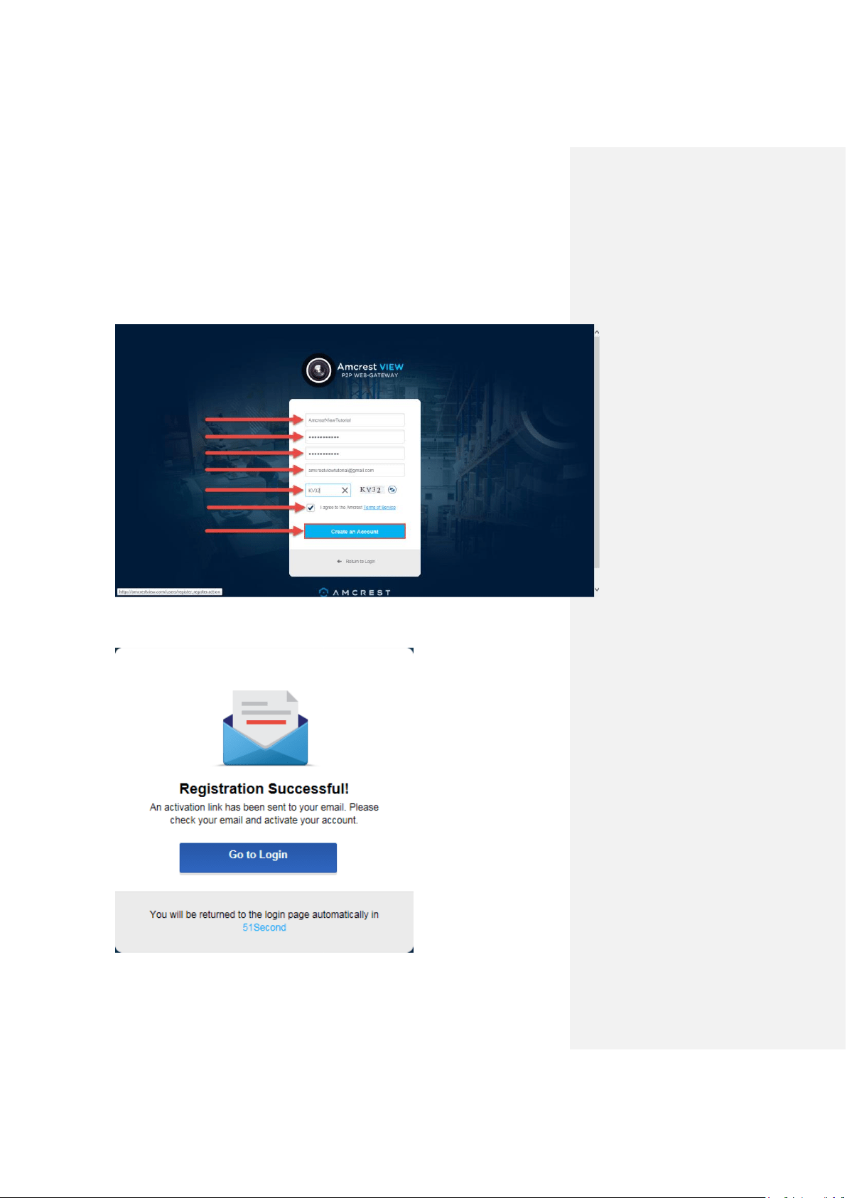
2. You will be taken to the registration form. Enter your Username, Password, then
Confirm Password, type your Email, enter the Verification Code, make sure the box is
checked confirming you’ve read the ‘Amcrest Terms of Service’, then click Create an
Account:
3. You will see the Registration Successful message and a confirmation email will be sent
to you:
Amcrest View Web Portal Setup User method
67
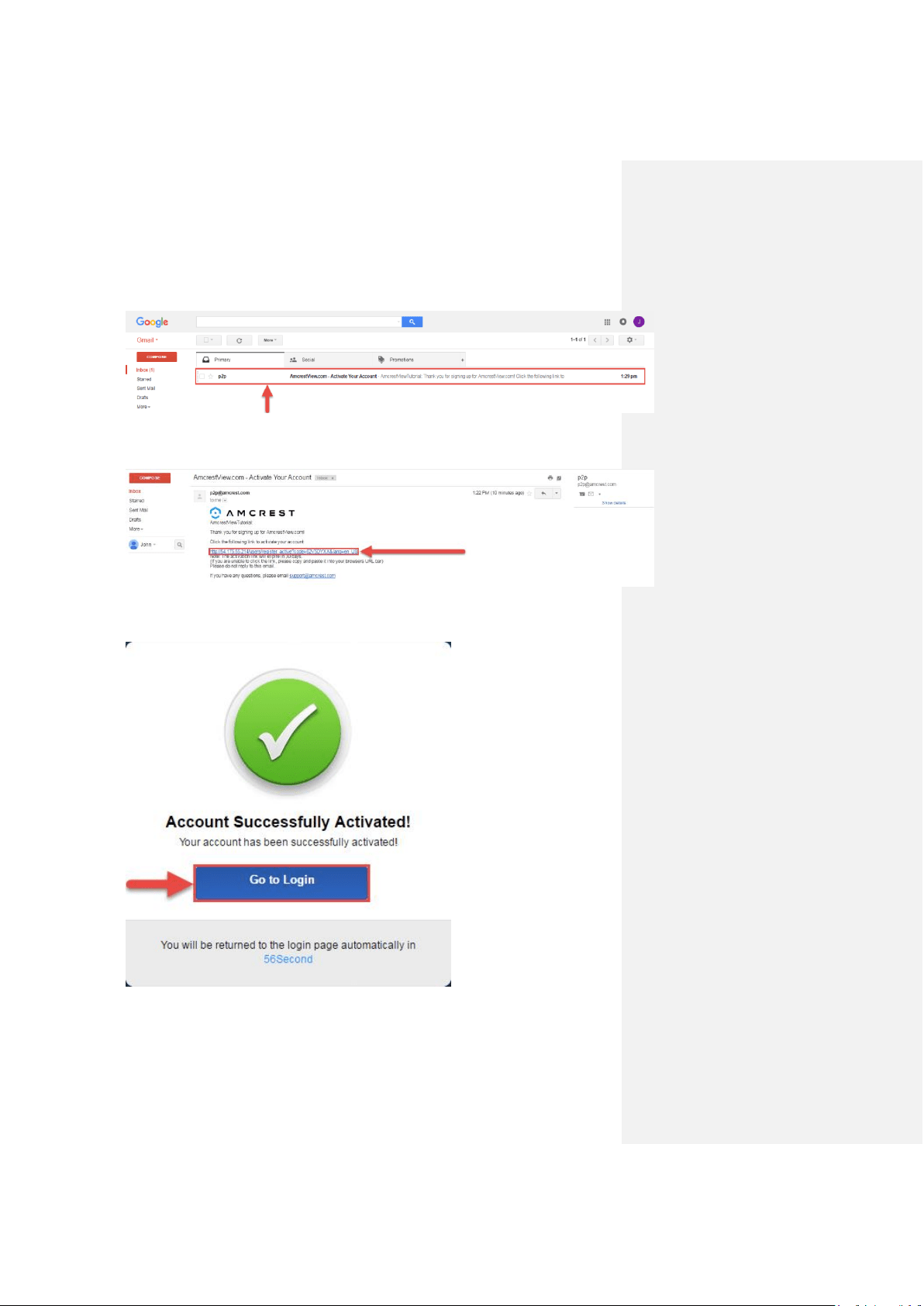
Check your email, and click the confirmation email from AmcrestView.com:
4. Once you’ve opened the email, click the confirmation link inside to complete your
registration:
5. You will be taken back to AmcrestView.com and shown confirmation that your account
has been activated. Click Go to Login:
Amcrest View Web Portal Setup User method
68
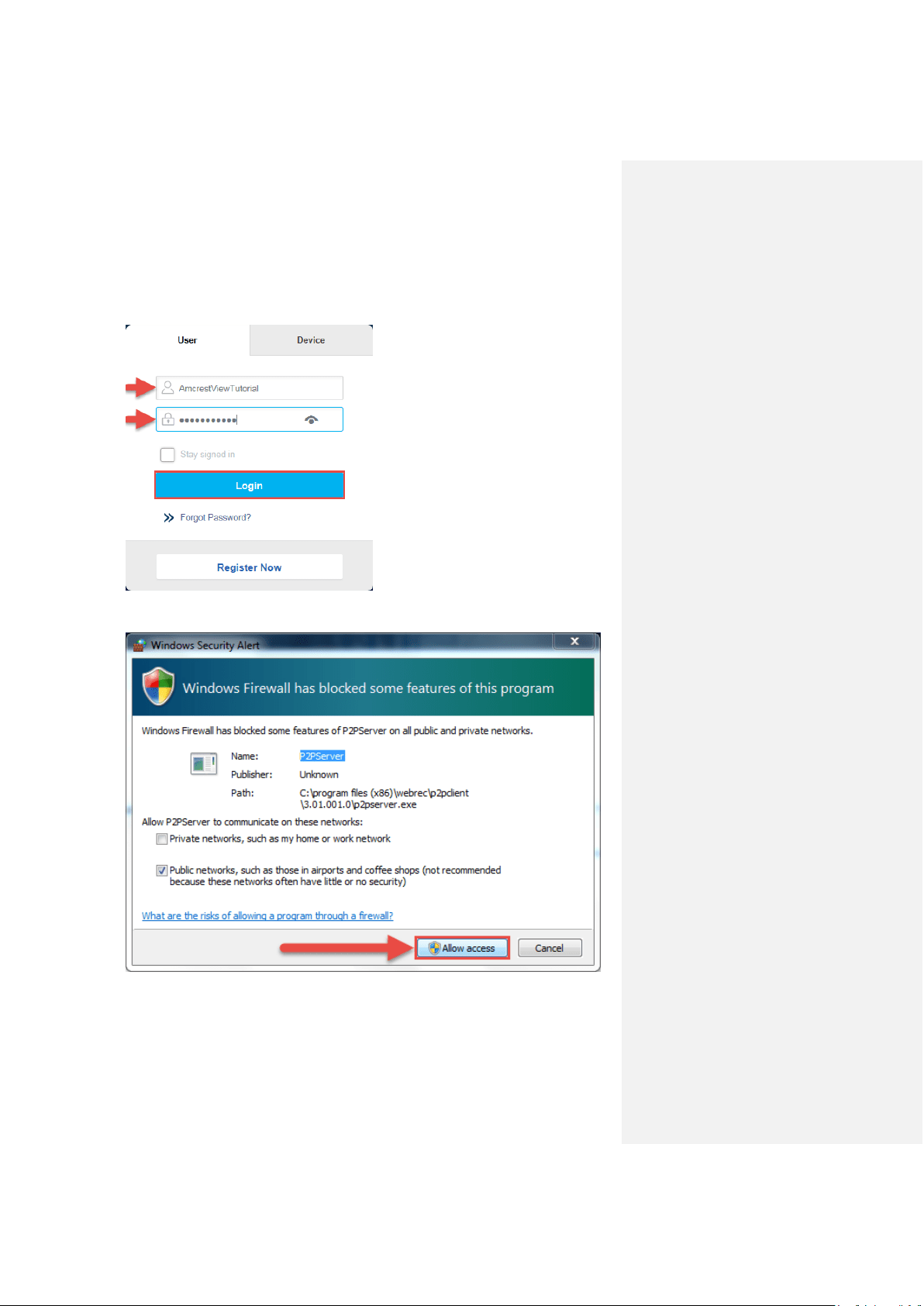
6. You will be taken back to the login screen. Enter your new AmcrestView.com username
and password, then click Login:
7. A popup will appear from your Windows Firewall. Click Allow access:
Amcrest View Web Portal Setup User method
69
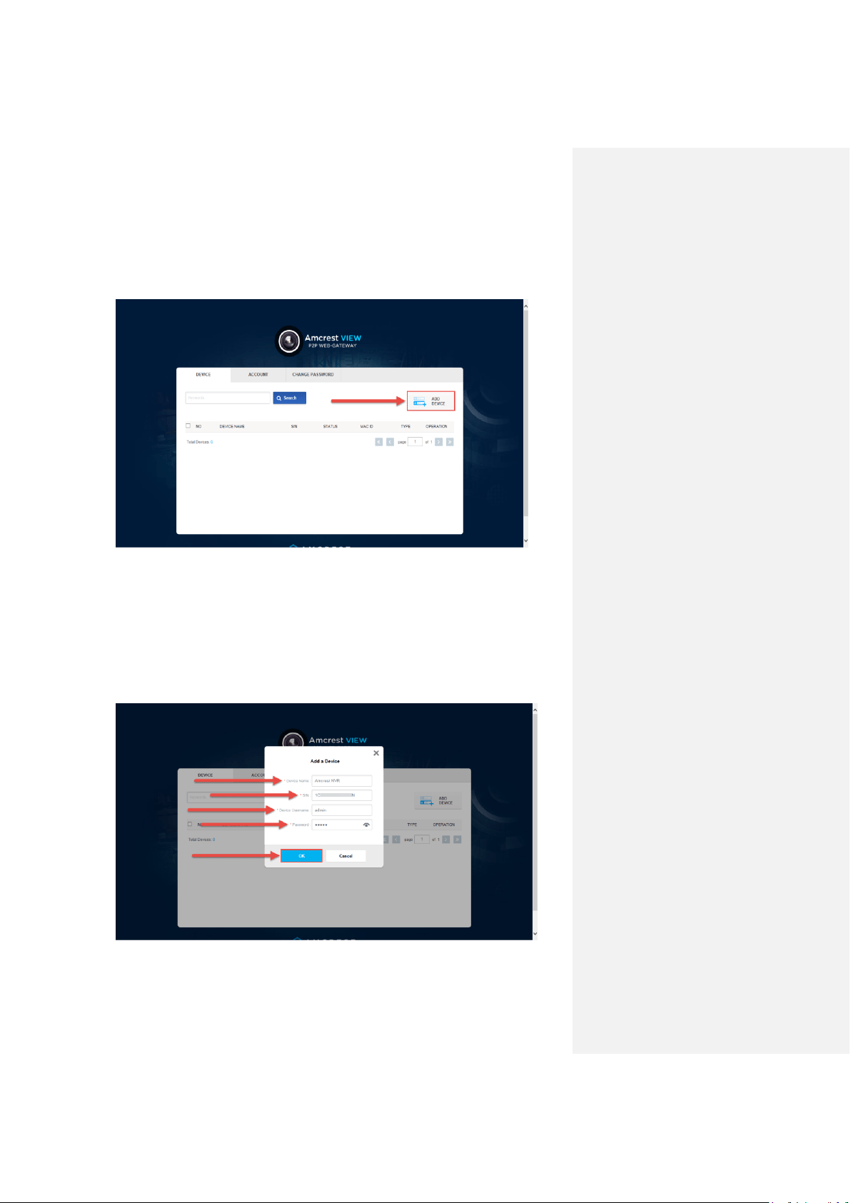
8. You will be taken to the main screen of your account. From here, click the Add Device
button:
9. Now you can enter your NVR’s information. Enter a Device Name (this can be anything).
Then, fill in the S/N (serial number) this can be found on the sticker attached to the
bottom of your NVR or through the web interface. Please refer to part 6 of this guide:
Amcrest View App Setup > Entering serial number manually(technical method -
harder).
Enter your username and password for the NVR, not the username and password you
just created for AmcrestView.com. To find your NVR login credentials, please refer to
part 4 of this guide: Console Setup (Login & Startup Wizard) > Logging in.
Finally, click OK:
Amcrest View Web Portal Setup User method
70
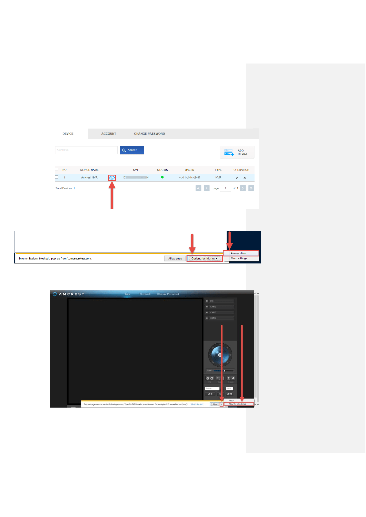
10. You will then see your NVR added to the device list on the main screen. Click the ‘eye’
icon to view the live feed:
11. Your browser will give you a notification asking you to allow popups from
AmcrestView.com. Click Options for this site, then click Always allow:
12. You will be taken to the live view page and given a notification to allow the plugin to pull
the video feed through here. Click the small arrow to the right of Allow, then click Allow
for all websites:
Amcrest View Web Portal Setup User method
71
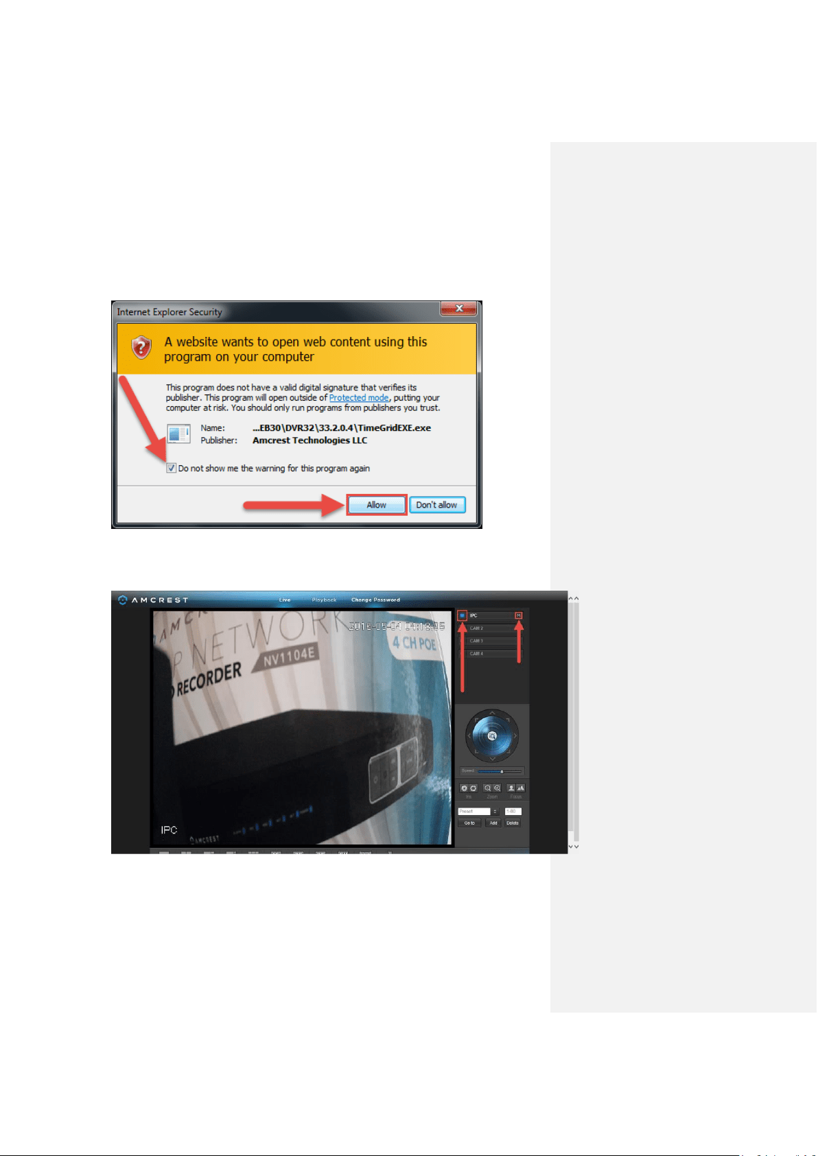
13. A final popup will appear asking you to confirm that you allow this plugin on your browser.
Mark the checkbox next to Do not show me the warning for this program again, then
click Allow:
14. Now you can enable any of your added cameras to see their live feeds. In the top-right
panel, there is a channel list. Click the small square icon to enable your feed for an
added camera to see the video feed:
Click the “S” to change it to an “M” which stands for “Main Stream” and will give you a full
HD quality video stream. To go back to “Sub Stream”, for lower quality video (that works
better on slower internet connections), click the “M” and change it to an “S” again.
Amcrest View Web Portal Setup Device method
72
Device method
To login to your NVR quickly, without having to register, you can use the device method. This
method still requires that you install a plugin, which is covered above, but can be done with only
the NVR’s login credentials and the serial number.
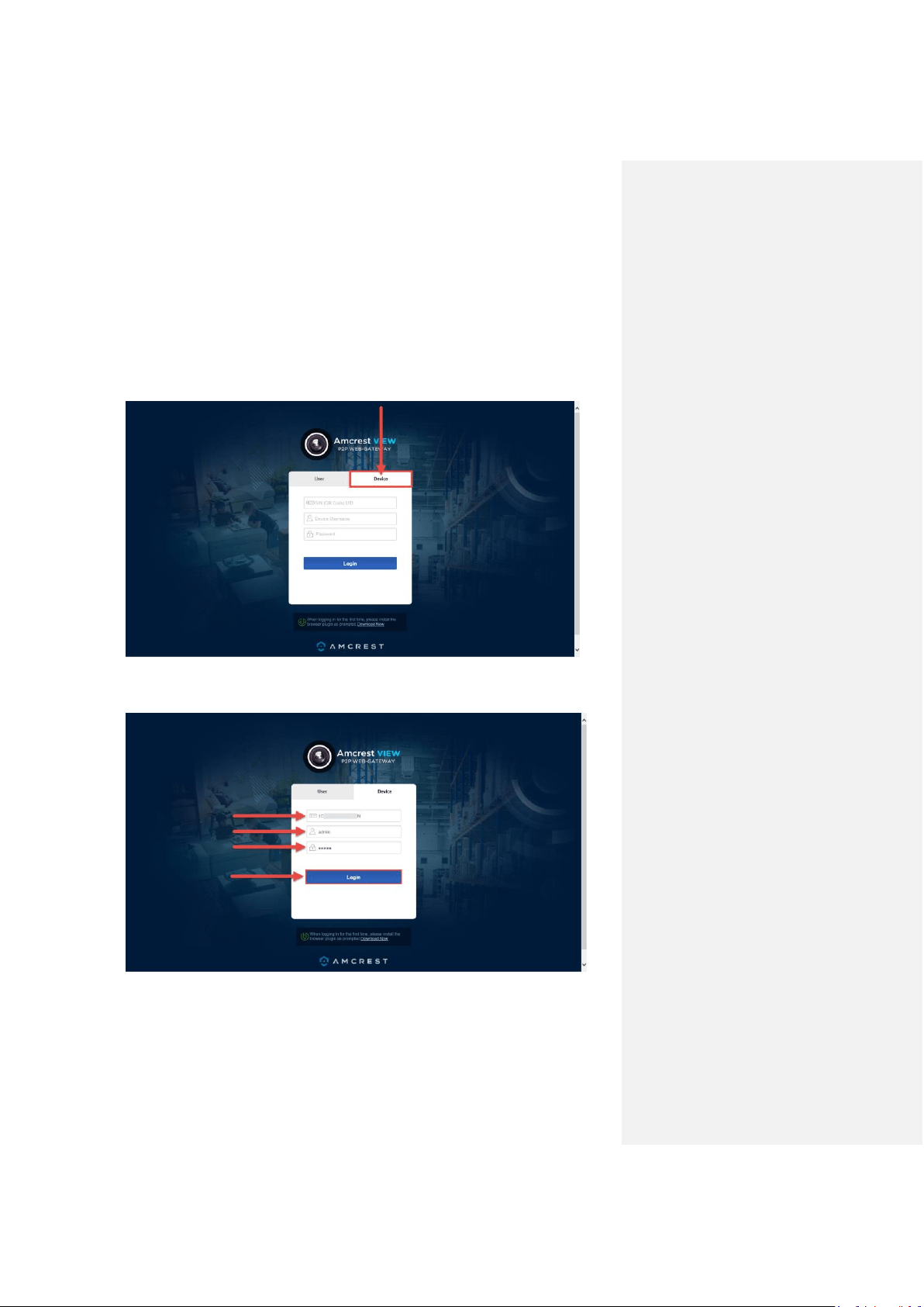
1. On the main login screen for AmcrestView.com, click the Device tab:
2. Enter your NVR’s S/N(serial number) into the top field, enter your NVR’s username and
password, then click Login.
To find your NVR’s login credentials, please refer to part 4 of this guide: Console Setup
(Login & Startup Wizard) > Logging in.
AmcrestView Web Interface Overview Live view section
73
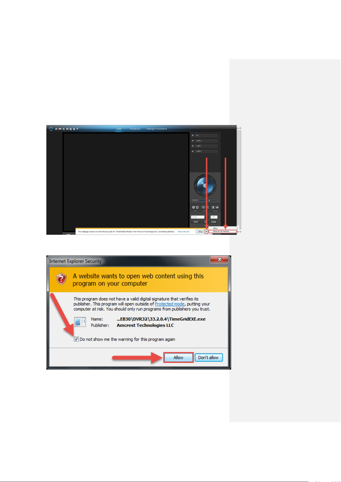
3. This will take you straight to the live view screen. You will see a notification from your
browser asking you to allow the plugin. Click the small arrow to the right of Allow, then
click Allow for all websites:
4. You will see a popup asking you to confirm that you allow this plugin. Check the box next
to Do not show me the warning for the program again, then click Allow:
AmcrestView Web Interface Overview Live view section
74
5. Now you can enable any of your added cameras to see their live feeds. In the top-right
panel, there is a channel list. Click the small square icon to enable your feed for an
added camera to see the video feed:
Click the “S” to change it to an “M” which stands for “Main Stream” and will give you a full
HD quality video stream. To go back to “Sub Stream”, for lower quality video (that works
better on slower internet connections), click the “M” and change it to an “S” again.
AmcrestView Web Interface Overview Device list section
75
AmcrestView Web Interface Overview
There are two main sections inside of the AmcrestView web interface: the main device list
section (for anyone logged in with a registered account) and the live view section (can be
accessed by both registered users and those accessing their NVRs using the device method
covered above.
Device list section
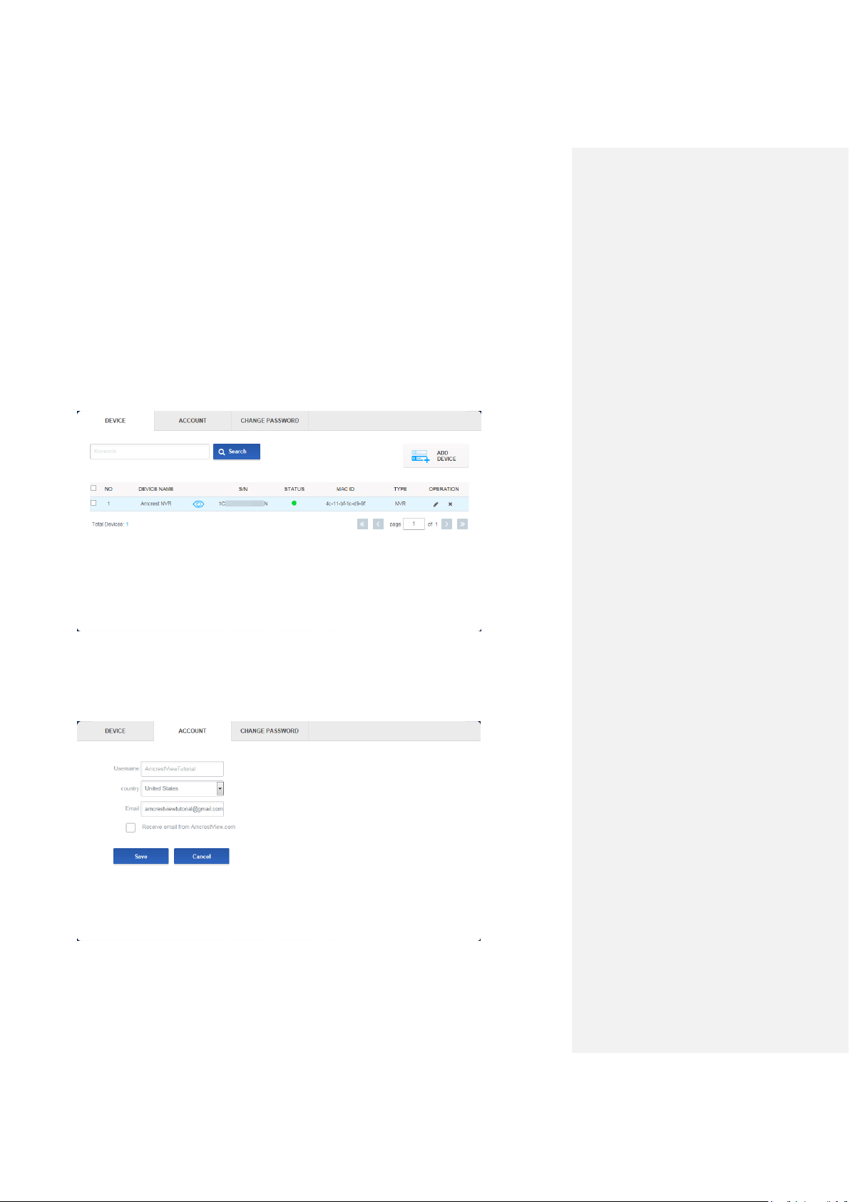
The device list section has 3 main tabs. The first is the DEVICE tab:
This page shows you a list of any added devices and is where you can click the ‘eye’ icon to view
your NVR’s live camera feeds. This is where you can ADD DEVICE, Search, edit, or delete your
added devices.
The next tab is the ACCOUNT tab:
AmcrestView Web Interface Overview Live view section
76
This is where you can see your Username, change your Country, see your Email, and enable
email notifications from AmcrestView.com.
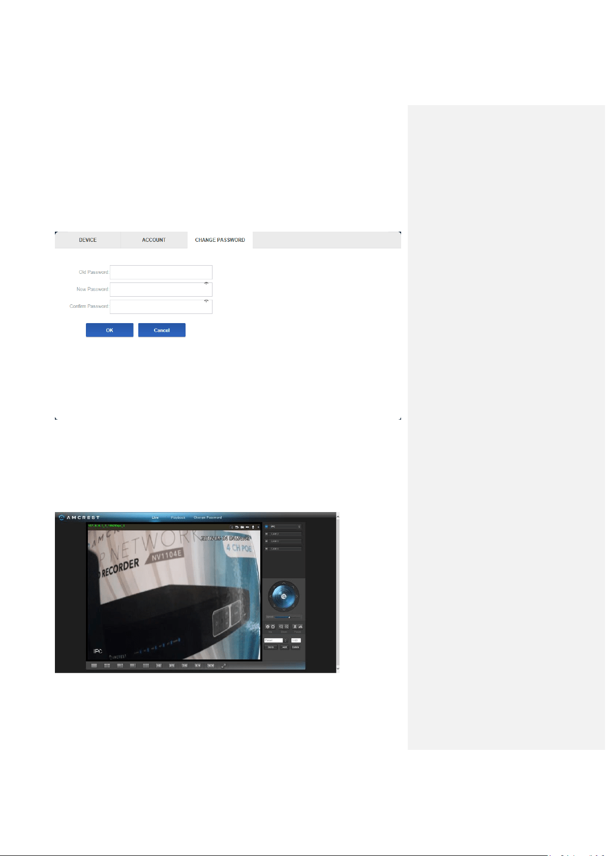
The last tab for the device list section is the CHANGE PASSWORD tab:
Here, you can change your password.
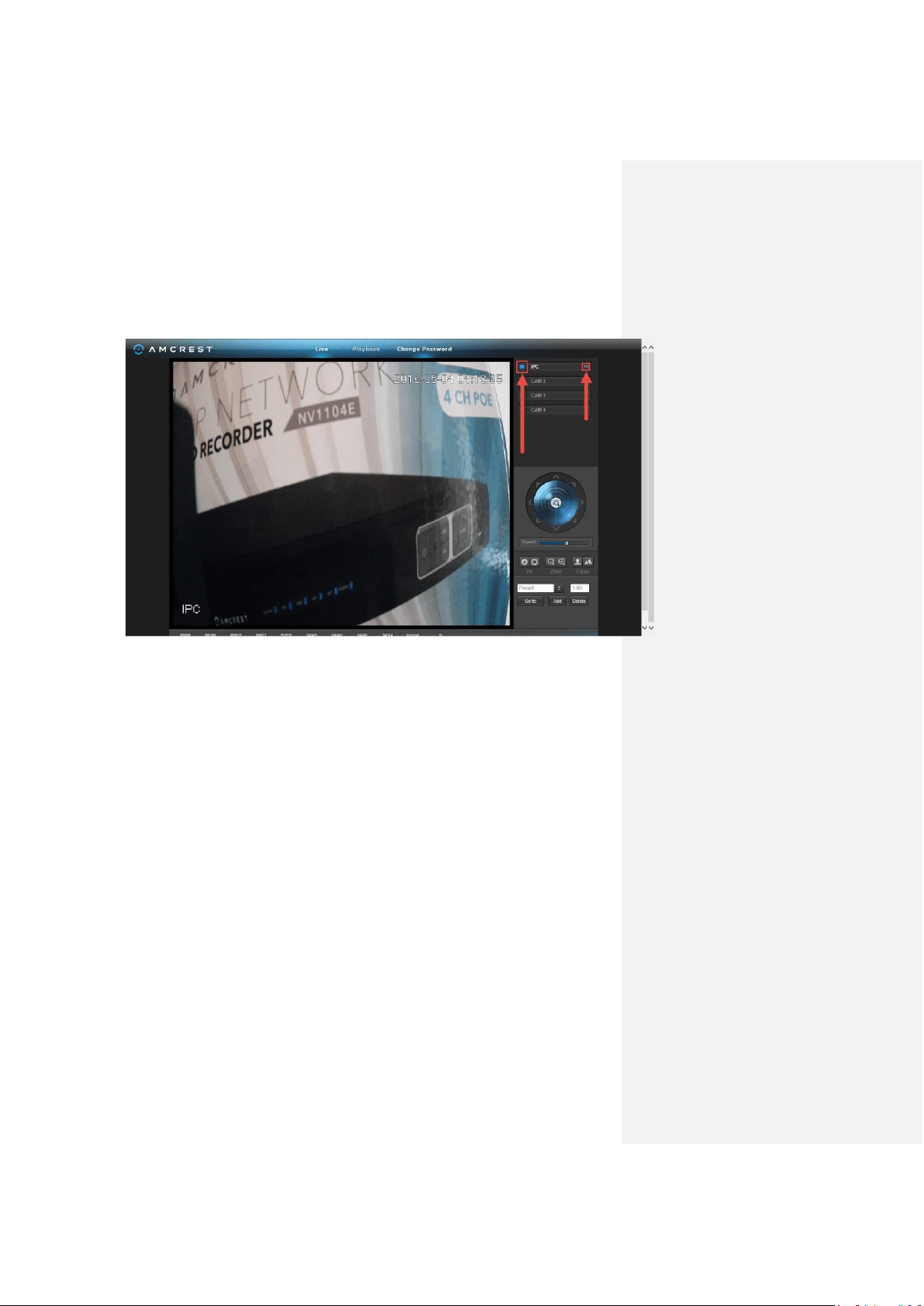
Live view section
The live view section is where you can see the live camera feeds and playback footage for any
cameras added to your NVR.
The first tab is the Live tab:
References & Contact Information
72
Here, you can enable the live feeds for any connected cameras, take snapshots, record
manually, view them in full screen, and more.
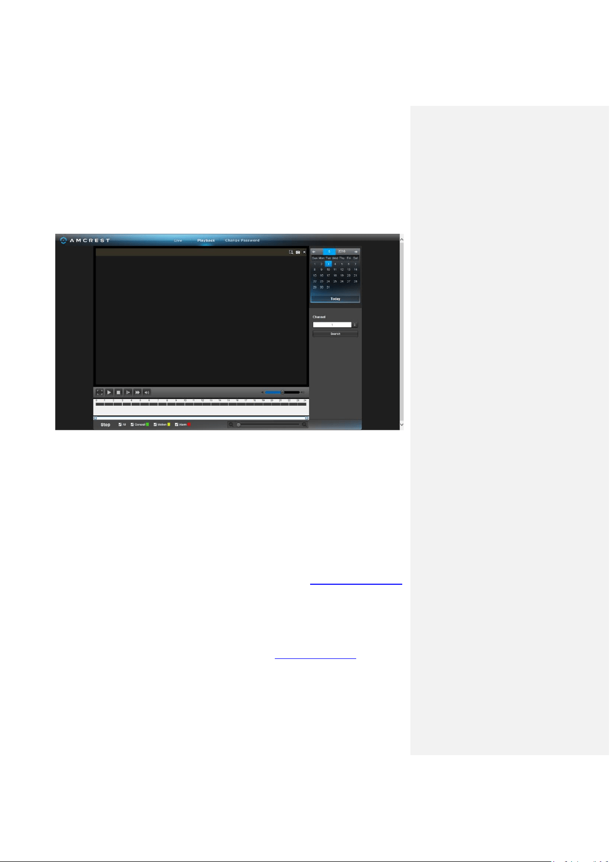
The next tab is the Playback tab:
Here, on the right panel, there is a calendar for you to choose which day you’d like to see footage
from, and you can choose a channel to select which camera you want to see footage from. The
timeline on the bottom allows you to play, stop, forward, etc.
Note: Keep in mind that you can see the live feeds from your cameras whether or not a hard
drive is installed in your NVR. However, you will need to have a hard drive installed and
recordings properly configured in order to view the playback.
8. References & Contact Information
For a detailed operational introduction, please refer to our CD included in your package for the
electronic version of the User Manual.
To view setup videos for many of the steps outlined in this guide, go to http://amcrest.com/videos
This quick start guide is for reference only. Slight differences may be found in the user interface.
All the designs and software here are subject to change without prior written notice.
All trademarks and registered trademarks mentioned are the properties of their respective owners.
If you have any questions or concerns, please contact us at su[email protected], or call us at
888-212-7538.