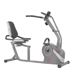
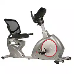
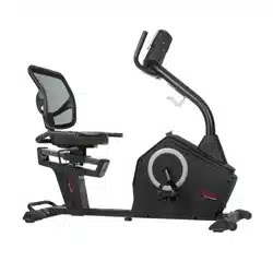
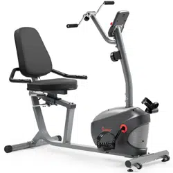
USER MANUAL CROSS TRAINER MAGNETIC RECUMBENT BIKE WITH ARM EXERCISERS
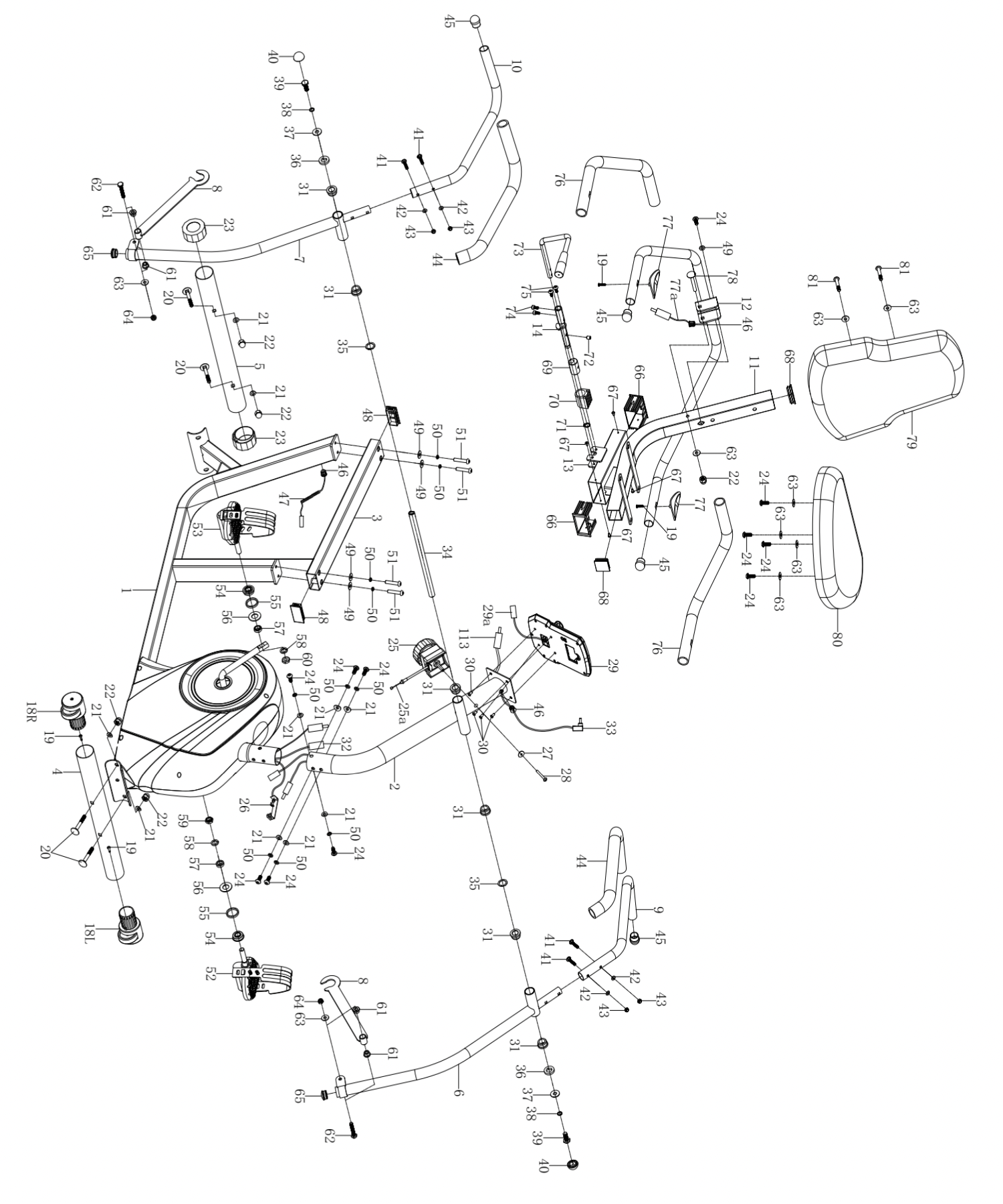
EXPLODED DIAGRAM 1
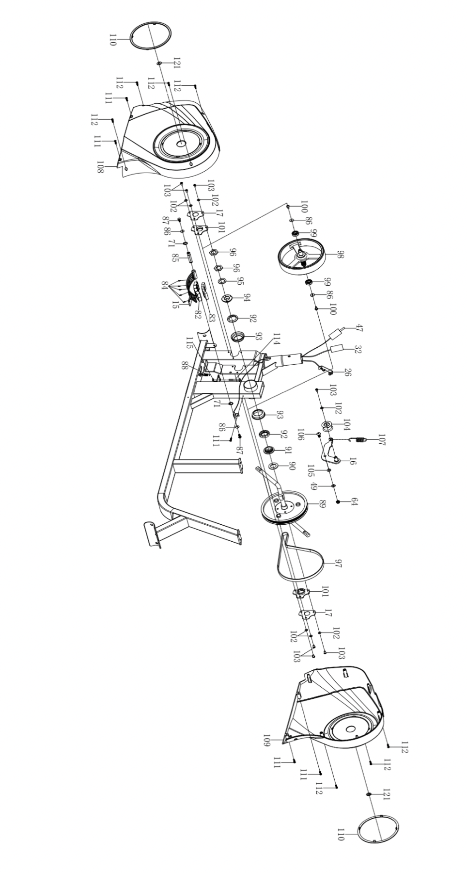
EXPLODED DIAGRAM 2
ASSEMBLY INSTRUCTIONS
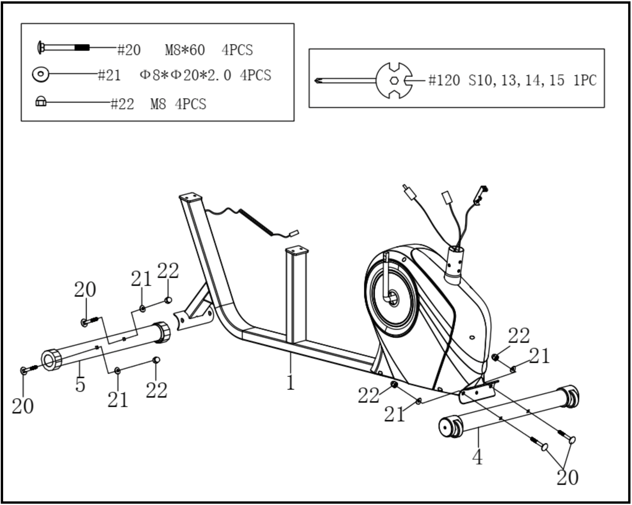
STEP 1: Attach the Front Stabilizer (No. 4) and Rear Stabilizer (No. 5) to the Main Frame (No. 1) with 4 Bolts (No. 20), 4 Nuts (No. 22), and 4 Arc Washers (No. 21). Tighten and secure with the Spanner (No. 120).
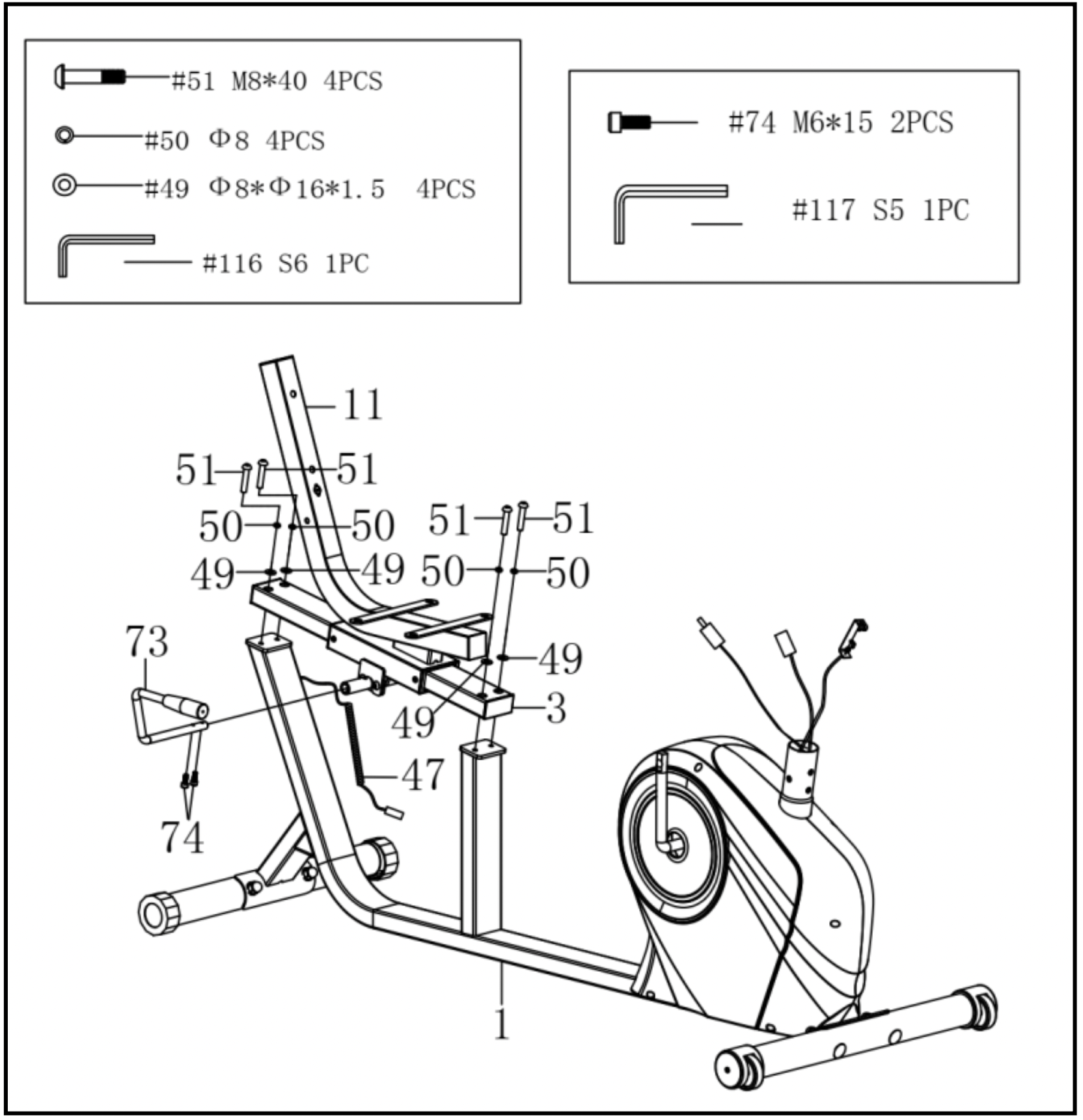
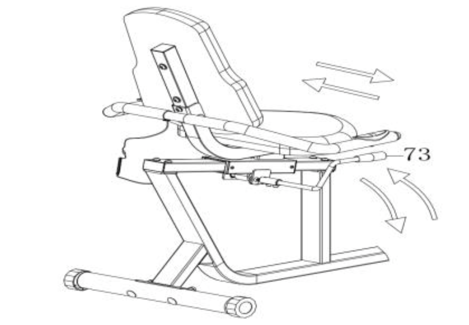
STEP 2: Attach the Brake Handle (No. 73) to the Seat Adjusting Tube (No. 3) with 2 Screws (No. 74). Tighten and secure with Allen Wrench (No. 117).
CAUTION: Please move Seat Support Bracket (No. 11) forward before assembling the Seat Adjusting Tube (No. 3). To adjust the seat forward or backward, press down Brake Handle (No. 73), then slide the seat to the desired position, lift the Brake Handle (No. 73) to tighten.
Attach the Seat Adjusting Tube (No. 3) to the Main Frame (No. 1) with 4 Washers (No. 49), 4 Spring Washers (No. 50) and 4 Bolts (No. 51). Tighten and secure with Allen Wrench (No. 116).
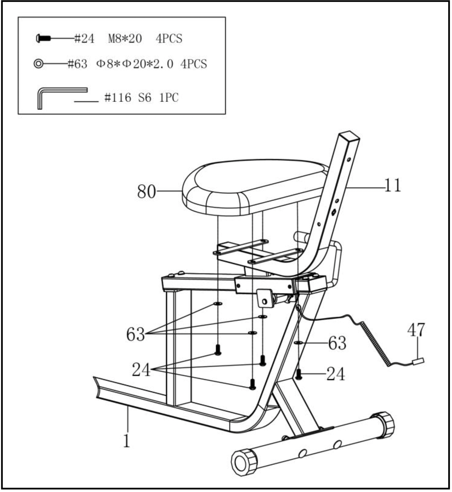
STEP 3: Remove 4 Screws (No. 24) and 4 Washers (No. 63) from Seat (No. 80) using the Allen Wrench (No. 116).
Attach the Seat (No. 80) to the Seat Support Bracket (No. 11) with 4 Screws (No. 24) and 4 Washers (No. 63) that were removed. Tighten and secure with Allen Wrench (No. 116).
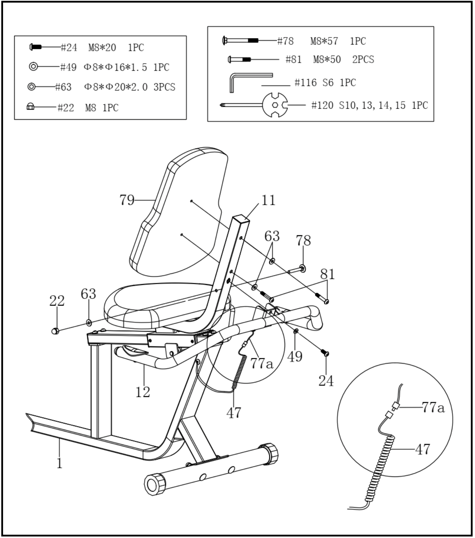
STEP 4: Attach the Handlebar (No. 12) onto the Seat Support Bracket (No. 11) with 1 Bolt (No. 78), 1 Washer (No. 63), 1 Nut (No. 22), 1 Screw (No. 24) and 1 Washer (No. 49). Tighten and secure with Spanner (No. 120) and Allen Wrench (No. 116).
Connect the Flexible Wire (No. 47) to the Handle Pulse Wire (No. 77a).
Attach the Backrest Cushion (No. 79) to the Seat Support Bracket (No. 11) with 2 Bolts (No. 81) and 2 Washers (No. 63). Tighten and secure with Allen Wrench (No. 116).
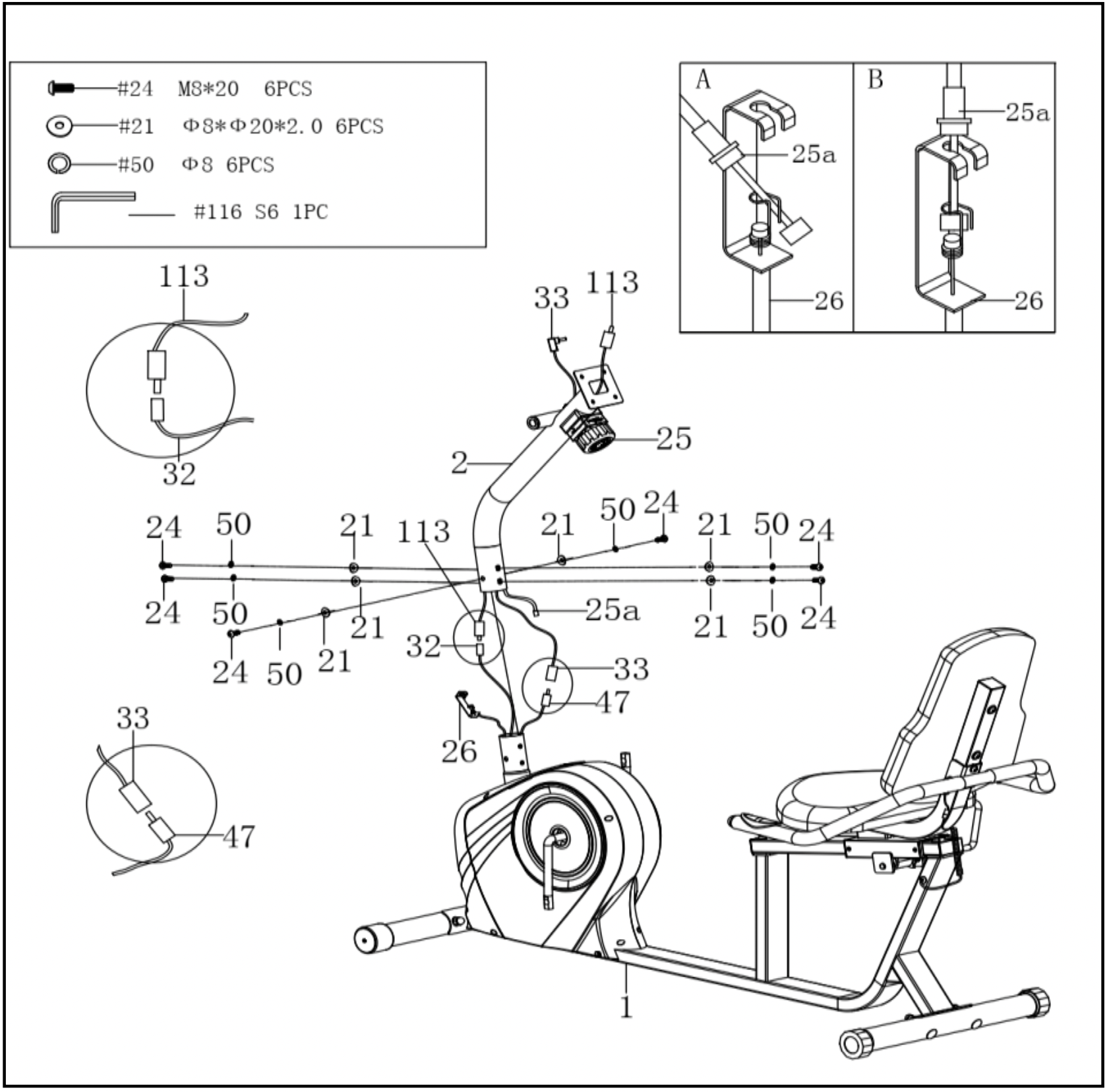
STEP 5: Remove 6 Screws (No. 24), 6 Arc Washers (No. 21) and 6 Spring Washers (No. 50) from the Main Frame (No. 1) with Allen Wrench (No. 116).
CAUTION: Please make sure the Tension Control Knob (No. 25) is at the lowest resistance level (level 1, all the way to the left) before you connect any wires together.
Attach the Tension Control Wire (No. 25a) into the metal bracket of Tension Wire (No. 26) as shown in drawing A. Then, pull Tension Control Wire (No. 25a) upward and insert it into the slot of metal bracket of Tension Wire (No. 26) as shown in drawing B. Make sure the metal fitting on Tension Control Wire (No. 25a) is secured in the metal bracket.
Connect the Handle Pulse Wire (No. 33) to Flexible Wire (No. 47); and connect Sensor Wire (No. 32) to the Extension Sensor Wire (No. 113). Insert the connecting wires into Front Post (No. 2).
Attach the Front Post (No. 2) to the Main Frame (No. 1) with 6 Screws (No. 24), 6 Arc Washers (No. 21) and 6 Spring Washer (No. 50) that were removed. Tighten and secure with Allen Wrench (No. 116).
NOTE: Be careful not to pinch any wires when attaching Front Post (No. 2) to Main Frame (No. 1)
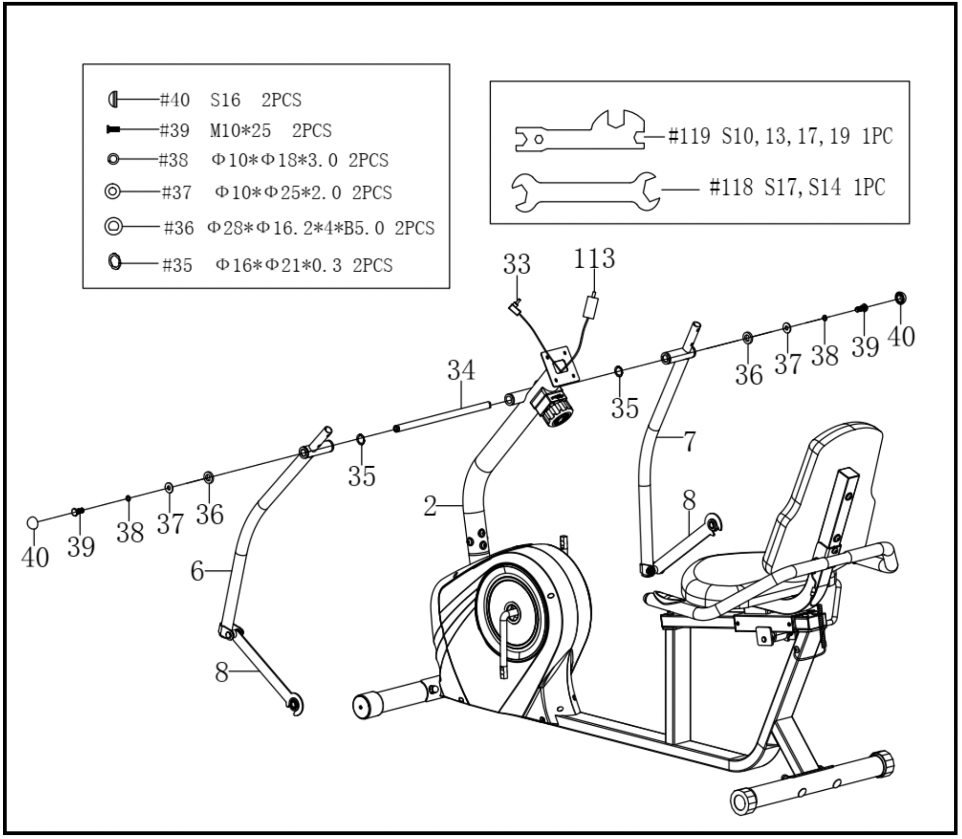
STEP 6: Remove 2 Screws (No. 39), 2 Spring Washers (No. 38), 2 D Washers (No. 36), 2 Washers (No. 37) and 2 Wave Washers (No. 35) from the Rotation Rod (No. 34) with Spanner (No. 118) and Spanner (No. 119).
Insert the Rotation Rod (No. 34) into the tube on the Front Post (No. 2). Then attach 2 Wave Washers (No. 35) to each side of the Rotation Rod (No. 34).
Attach the Left & Right Swing Tubes (No. 6 & No. 7) to Rotation Rod (No. 34) with 2 Screws (No. 39), 2 Spring Washers (No. 38), 2 Washers (No. 37), and 2 D Washers (No. 36) that were removed. Ensure that the notch in D Washer (No. 36) is aligned with the divot of the Rotation Rod (No. 34). Tighten and secure with Spanner (No. 118) and Spanner (No. 119). Then cover with 2 End Caps (No. 40).
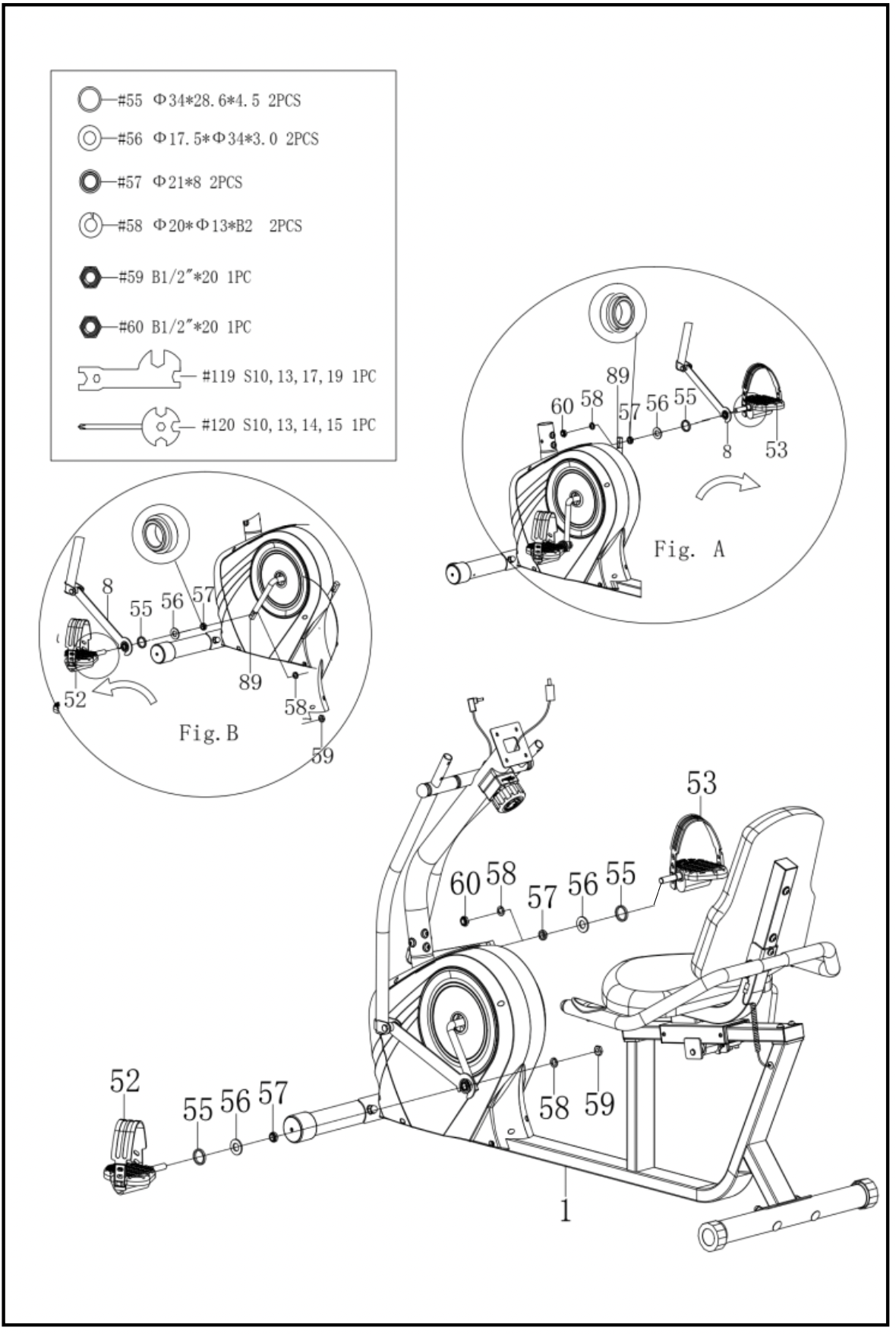
STEP 7: Remove the 2 Washers (No. 56), 2 Spacers (No. 55), 2 Sleeves (No. 57), 2 Spring Washers (No. 58), 1 Left Nylon Nut (No. 59), and 1 Right Nylon Nut (No. 60) from the Left & Right Pedals (No. 52 & No. 53).
Insert Left Pedal (No. 52) into Connecting Rod (No. 8), then attach 1 Spacer (No. 55), 1 Washer (No. 56), and 1 Sleeve (No. 57). Connect those parts to the left side of Belt Pulley with Crank (No. 89). Turn the Left Pedal (No. 52) counter-clockwise as tightly as you can with your hand, then use Spanner (No. 119) and Spanner (No. 120) to screw the Left Nylon Nut (No. 59) and the Spring Washer (No. 58) clockwise onto the thread end of Left Pedal (No. 52). (See Fig. B)
Insert Right Pedal (No. 53) into Connecting Rod (No. 8), then attach 1 Spacer (No. 55), 1 Washer (No. 56), and 1 Sleeve (No. 57). Connect those parts to the right side of Belt Pulley with Crank (No. 89). Turn the Right Pedal (No. 53) clockwise as tightly as you can with your hand, then use Spanner (No. 119) and Spanner (No. 120) to screw the Right Nylon Nut (No. 60) and the Spring Washer (No. 58) counter-clockwise onto the thread end of Right Pedal (No. 53). (See Fig. A)
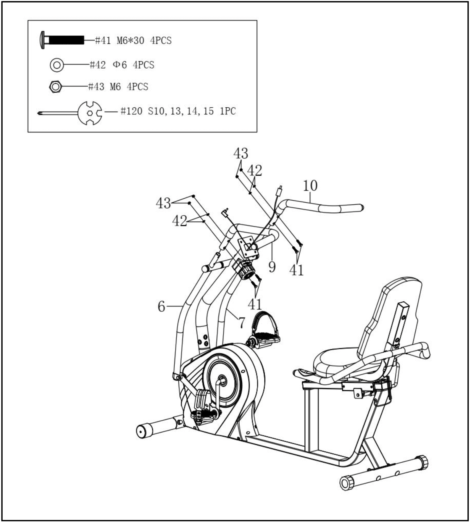
STEP 8: Attach the Left & Right Handlebars (No. 9 & No. 10) to the Left & Right Swing Tubes (No. 6 & No. 7) with 4 Bolts (No. 41), 4 Arc Washers (No. 42), and 4 Nuts (No. 43). Tighten and secure with the Spanner (No. 120).
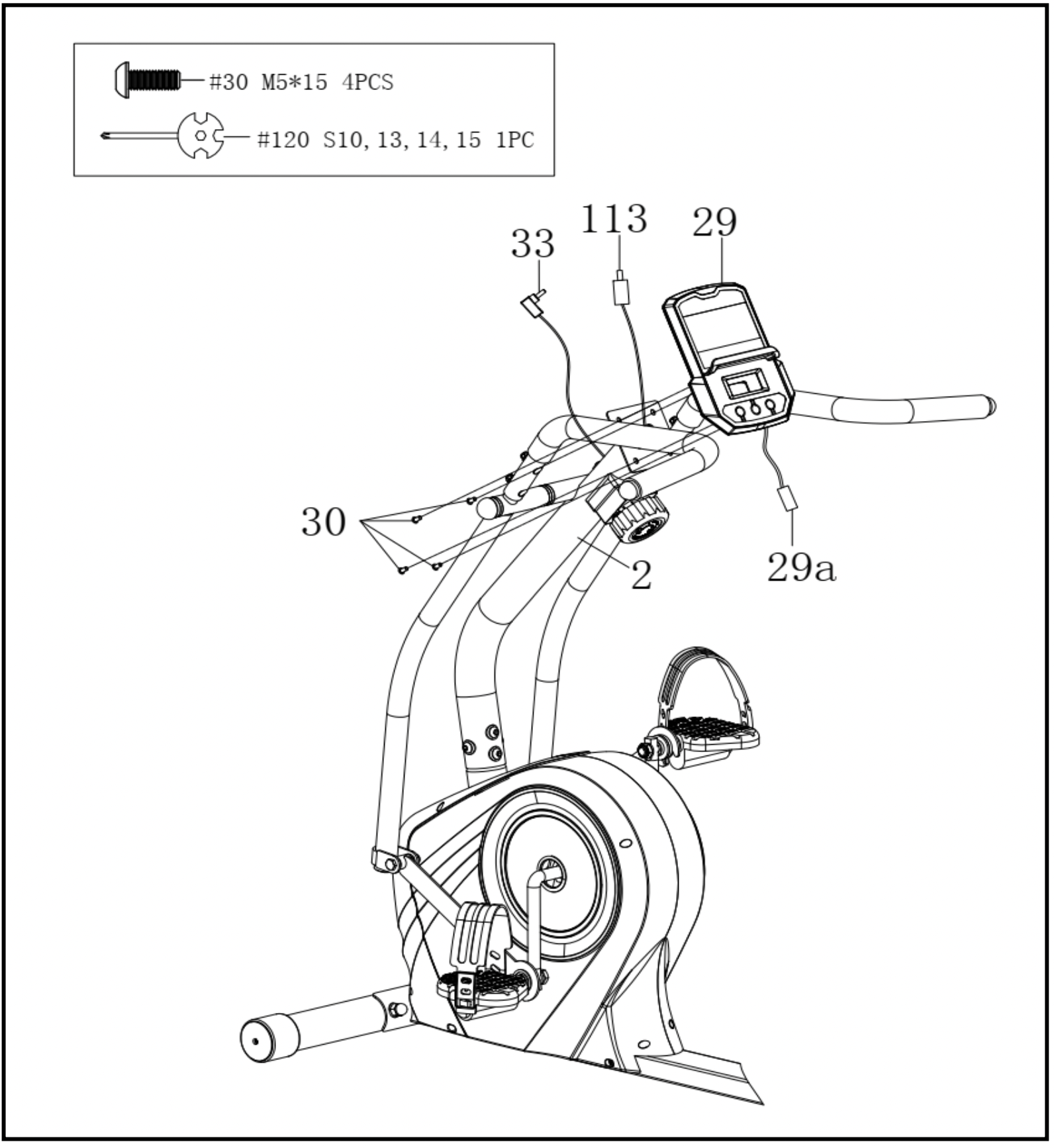
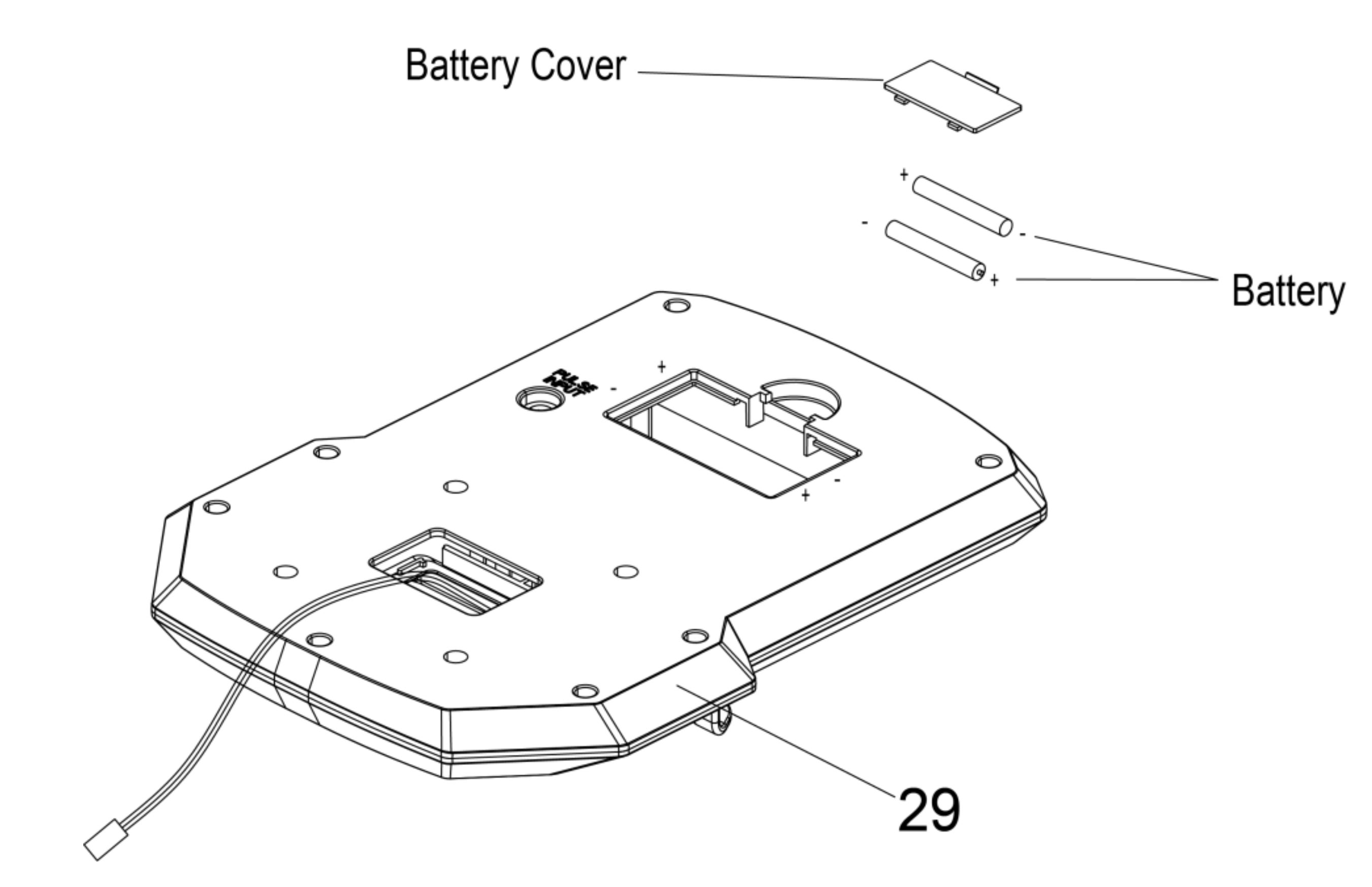
STEP 9: Remove 4 Screws (No. 30) from the back of the Computer (No. 29) with the Spanner (No. 120).
Connect the Extension Sensor Wire (No. 113) to the Computer Wire (No. 29a). Then insert them into the Front Post (No. 2).
Plug the Handle Pulse Wire (No. 33) into the Pulse Input jack on the back of Computer (No. 29).
Attach Computer (No. 29) to the top end of the Front Post (No. 2) with 4 Screws (No. 30) that were removed. Tighten and secure with Spanner (No. 120).
The assembly is complete!
BATTERY INSTALLATION & REPLACEMENT
BATTERY INSTALLATION
- Take out 2 AAA batteries from computer box.
- Press the buckle of battery cover on the Computer (No. 29), then remove battery cover.
- Install 2 AAA batteries into the battery case on the back of the Computer (No. 29). Pay attention to the battery + and – poles before installing.
- Press the buckle of battery cover, then put the battery cover back to the back of the Computer (No. 29).
The installation is complete!
BATTERY REPLACEMENT
- Press the buckle of battery cover on the back of the Computer (No. 29), then remove battery cover.
- Remove the 2 old AAA batteries in the battery case and install 2 new AAA batteries into the battery case on the back of the Computer (No. 29). Pay attention to the battery + and –poles before installing.
- Press the buckle of battery cover, then put the battery cover back to the back of the Computer (No. 29).
The replacement is complete!
BATTERY DISPOSAL
Dispose the batteries according to the laws and regulations of your local region. Some batteries may be recycled. When disposing or recycling, do not mix battery types.
ADJUSTMENTS GUIDE
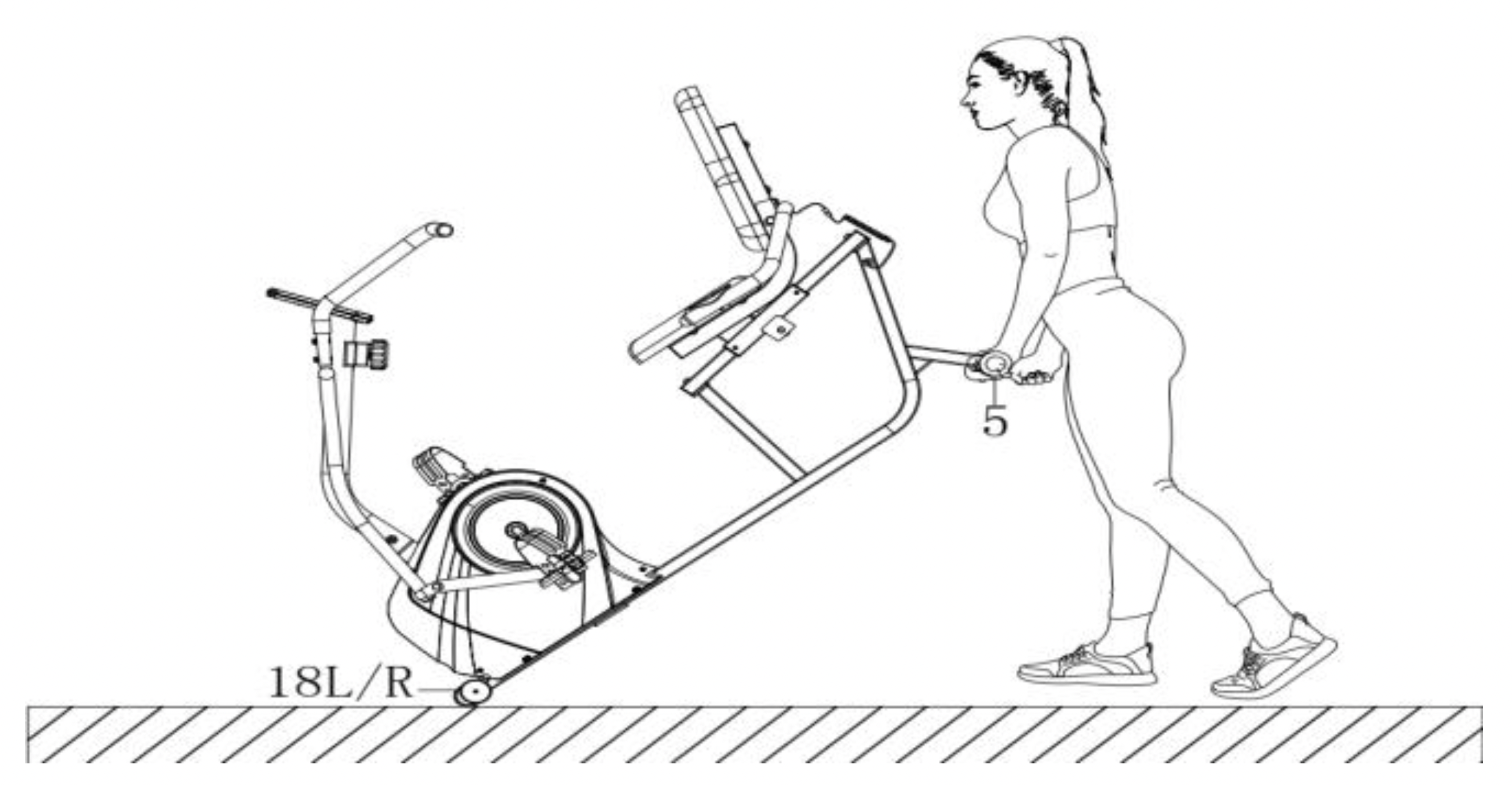
MOVING THE RECUMBENT BIKE
Lift the Rear Stabilizer (No. 5) and tilt the recumbent bike until the transportation wheels on the Left & Right End Caps (No. 18L/R) touch the ground. Now you can transport the recumbent bike to the desired location with ease.
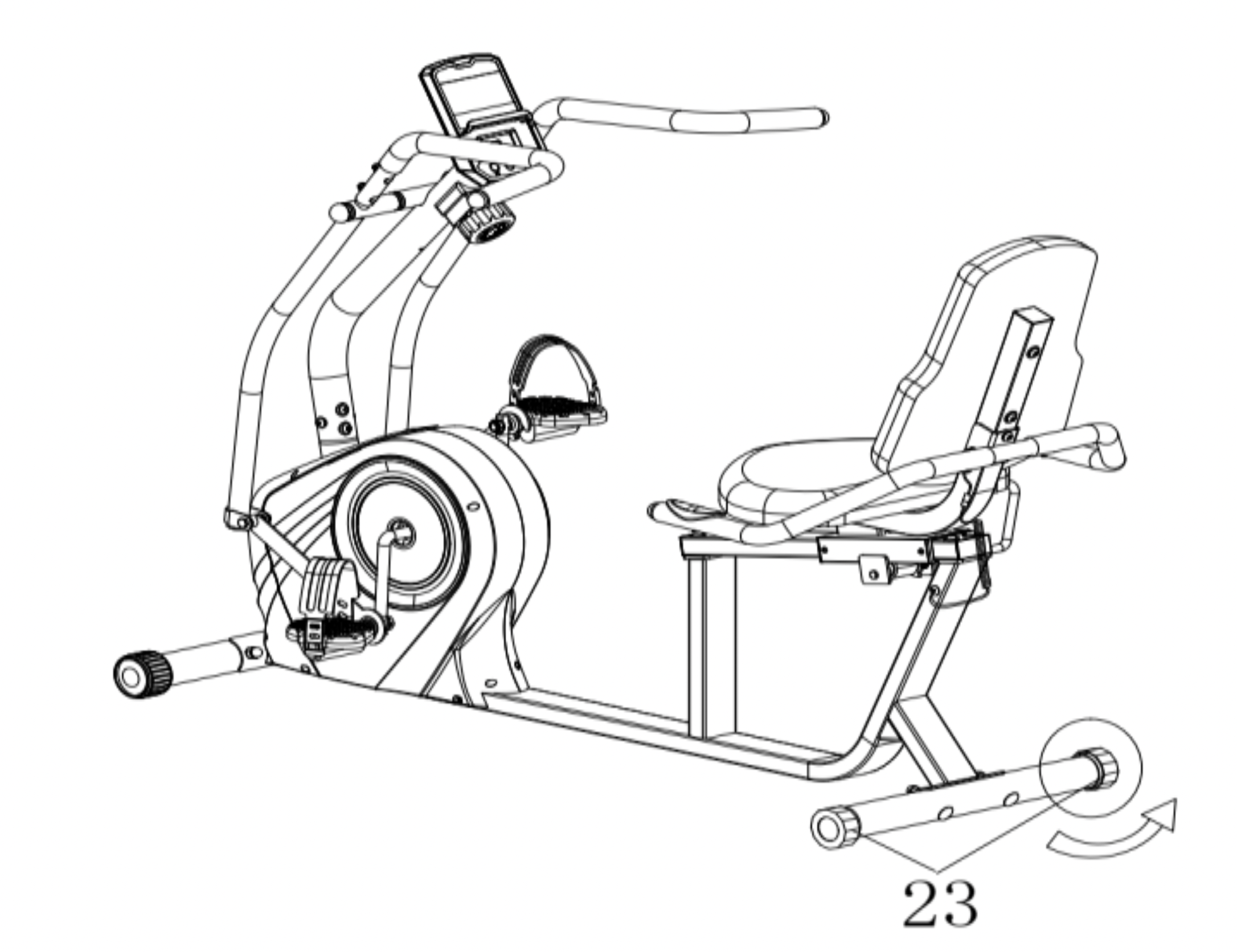
ADJUSTING THE BALANCE
In order to achieve a smooth and comfortable ride, you must ensure that the recumbent bike is stabled and secured. If you notice that the recumbent bike is unbalanced during use, you should adjust the End Caps (No. 23) located on the rear stabilizer until the recumbent bike becomes levelled with the floor surface.
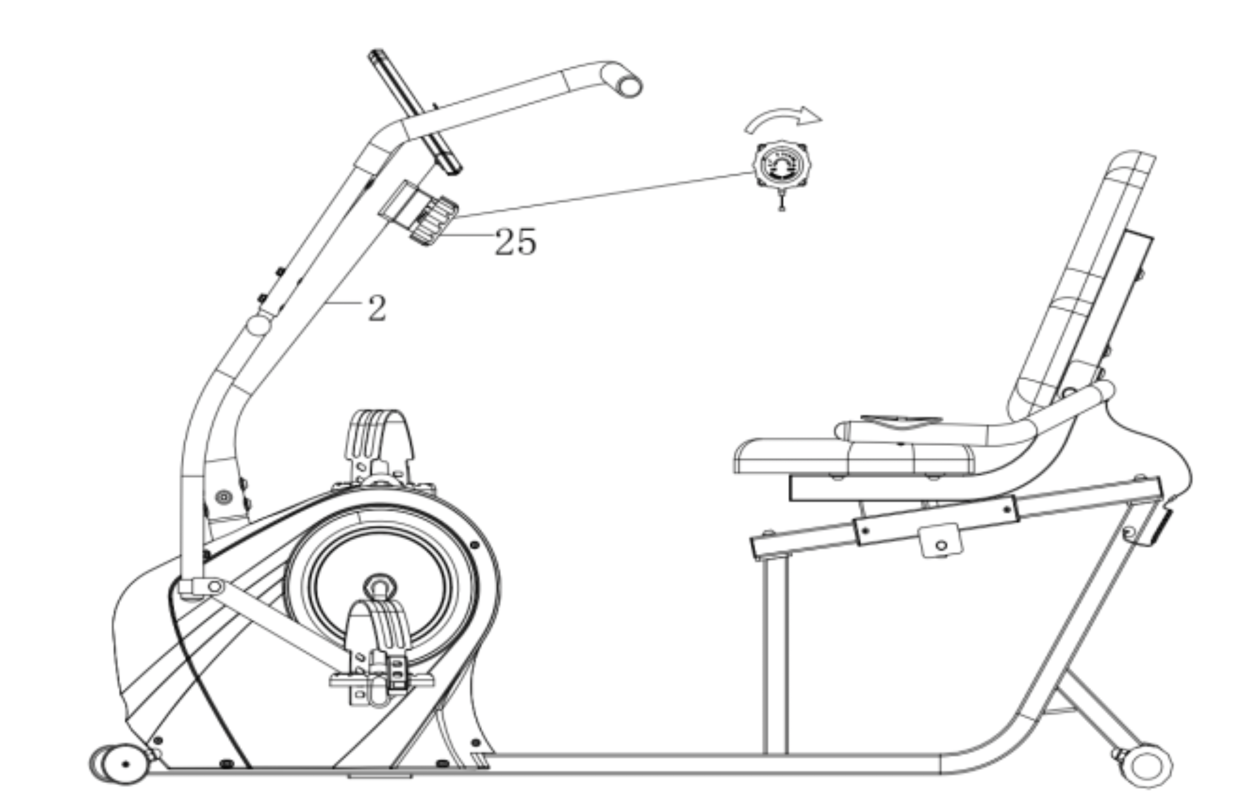
ADJUSTING THE TENSION
Adjust the tension by rotating the Tension Control Knob (No. 25) clockwise to increase the level of resistance. Rotate the Tension Control Knob (No. 25) counter-clockwise to decrease the level of resistance.
Tension levels are set at Level 1 being the lowest and Level 8 being the highest.
ADJUSTING THE SEAT
To adjust the seat forward or backward, press down Brake Handle (No. 73), then slide the seat to the desired position, lift the Brake Handle (No. 73) to tighten.
CLEANING
The recumbent bike can be cleaned with a soft, clean, damp cloth. Do not use abrasives or solvents on plastic parts. Please wipe your perspiration off the recumbent bike after each use. Be careful not to get excessive moisture on the computer display panel as thi s might cause electrical hazard or electronics to fail. Please keep the recumbent bike, especially the computer, out of direct sunlight to prevent screen damage. Please inspect all assembly bolts and pedals on the recumbent bike for proper tightness every week.
STORAGE
Store the recumbent bike in a clean and dry environment, away from children.
EXERCISE COMPUTER
FUNCTION BUTTONS:
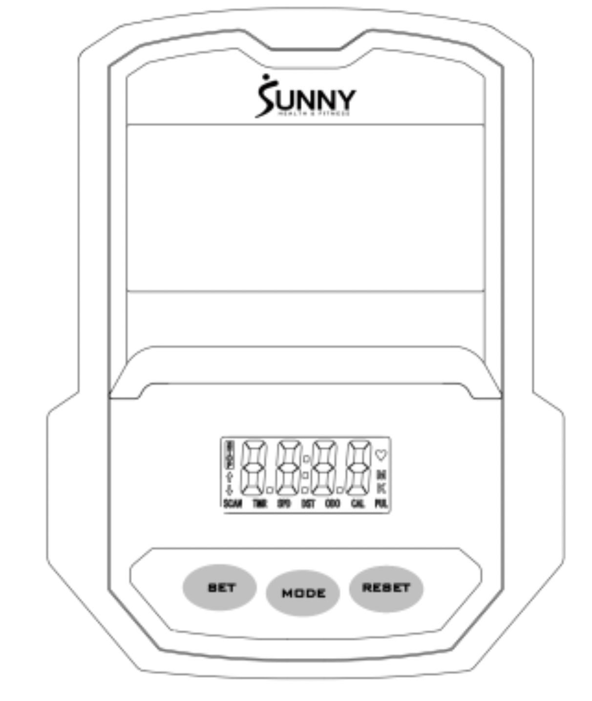
MODE:
- Press the button to select TIME, DISTANCE, and CAL to preset.
- Press the button for selection function display value on LCD or enter after setting.
- Press the button and hold for 3 seconds to reset all values except odometer to zero.
(When user replaces the batteries, all the values will reset to ZERO automatically).
SET: To set up the target value of TIME, DISTANCE, and CAL. Press the button and hold for 2 seconds to speed up the increment.
RESET: Press the button to reset function value when setting.
Press the button and hold for 3 seconds to reset all values except odometer to zero (When the user replaces batteries, all the values will reset to ZERO automatically).
FUNCTIONS & OPERATIONS:
- BATTERY INSTALLATION:
Please install 2 AAA 1.5V batteries in the battery case on the back of computer. (Whenever batteries are removed, all the function values will be reset to zero.)
- AUTO ON/OFF:
Once the user begins to exercise, the computer will show the workout value automatically. After about 4 minutes of inactivity, the computer will turn off. Odometer value does not reset to 0 when the computer turns off. When the user starts to exercise again, the workout value of odometer will accumulate continuously.
- AUTO SCAN:
After the computer is powered on, press MODE button, the LCD will display all functions values from TIME-SPEED-DISTANCE-CALORIES-ODOMETER-PULSE. Each value will be held for 6 seconds.
- SPEED:
Displays the current training speed from 0.0 to 99.9 MPH (Miles per hour).
- DISTANCE:
Accumulates total distance from 0.0 up to 9999 M (Miles). The user may preset target distance by pressing the SET & MODE buttons. Each increment is 0.1 M (Miles).
Automatically counts down from targeting value during exercise.
- TIME:
Accumulates total time from 00:00 up to 99:59. The user may preset target time by pressing SET & MODE buttons. Each increment is 1 minute.
Automatically counts down from targeting value during exercise.
- CALORIES:
Accumulates calories burned during training from 0 to 9999 Cal. The user may also preset the target calories before training by pressing the SET & MODE buttons. Each setting increase is 1 Cal. Automatically counts down from targeting value during exercise.
Note: This data is a rough guide which cannot be used in medical treatment.
- ODOMETER:
Displays the total accumulated distance from 0 to 9999 M (Miles). User can also press MODE button to display the odometer value.
- PULSE:
The computer will display the user's heart rate in beats per minute during training.
Note: This data is a rough guide which cannot be used in medical treatment.
- RESET:
Press the button and hold for 3 seconds to reset all values except odometer to zero.
NOTE:
- If the computer display is abnormal, please re-install the new batteries and try again. Always change both batteries at the same time. Do not mix battery types and do not mix old and new batteries.
- Battery Spec: 1.5V UM-4 or AAA (2PCS).
- Dispose the batteries safely, according to your state and regional guidelines.
TROUBLESHOOTING
| PROBLEM |
SOLUTION |
|
There is no display on the computer.
|
- Remove the computer and verify that the wire from the computer is properly connected to the wire that comes from the front post.
- Check if the batteries are correctly positioned and battery springs are inproper contact with batteries.
- The batteries in the computer may be unresponsive. Change to new batteries.
|
|
The recumbent bike wobbles when in use.
|
Turn the rear end caps on the rear stabilizer as needed to level the recumbent bike.
|
|
The recumbent bike makes squeaking noise when in use.
|
Some bolts on the recumbent bike might have become loose. Please inspect all the bolts and tighten any loosened bolts.
|
We thank you for choosing our product. To ensure your safety and health, please use this equipment correctly. It is important to read this entire manual before assembling and using the equipment. Safe and effective use can only be achieved if the equipment is assembled, maintained, and used properly. It is your responsibility to ensure that all users of the equipment are informed of all warnings and precautions.
- Before starting any exercise program, you should consult your physician to determine if you have any medical or physical conditions that could put your health and safety at risk or prevent you from using the equipment properly. Your physician’s advice is essential if you are taking medication that affects your heart rate, blood pressure, or cholesterol level.
- Be aware of your body’s signals. Incorrect or excessive exercise can damage your health. Stop exercising if you experience any of the following symptoms: pain, tightness in your chest, irregular heartbeat, shortness of breath, lightheadedness, dizziness, or feelings of nausea. If you do experience any of these conditions, you should consult your physician before continuing with your exercise program.
- Keep children and pets away from the equipment. The equipment is designed for adult use only.
- Use the equipment on a solid, flat level surface with a protective cover for your floor or carpet.
To ensure safety, the equipment should have at least 2 feet (60 CM) of free space all around it.
- Ensure that all nuts and bolts are securely tightened before using the equipment. The safety of the equipment can only be maintained if it is regularly examined for damage and/or wear and tear.
- Always use the equipment as indicated. If you find any defective components while assembling or checking the equipment, or if you hear any unusual noises coming from the equipment during exercise, discontinue use of the equipment immediately and do not use until the problem has been rectified.
- Wear suitable clothing while using the equipment. Avoid wearing loose clothing that may become entangled in the equipment.
- Do not place fingers or objects into the moving parts of the equipment.
- The maximum weight capacity of this unit is 265 pounds (120 KG).
- The equipment is not suitable for therapeutic use.
- To avoid bodily injury and/or damage to the product or property, proper lifting and moving are required.
- Your product is intended for use in cool, dry conditions. You should avoid storage in extreme cold, hot, or damp areas as this may lead to corrosion and other related problems.
- This equipment is designed for indoor and home use only; it is not intended for commercial use.