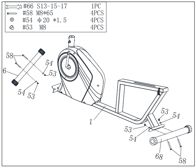
STEP 1: Attach the Front & Rear Stabilizers (No. 6 & No. 68) onto the Main Frame (No. 1) with 4 Cross Head Bolts (No. 58), 4 Arc Washers (No. 54), and 4 Cap Nuts (No. 53). Tighten with the Spanner (No. 66).
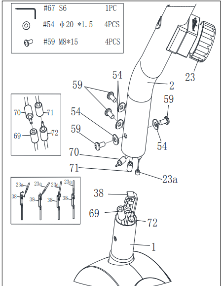
STEP 2: Connect the Sensor Wire 2 (No. 70) with Sensor Wire 1 (No. 69), connect the Sensor Wire 3 (No. 71) with the Sensor Wire 4 (No. 72).
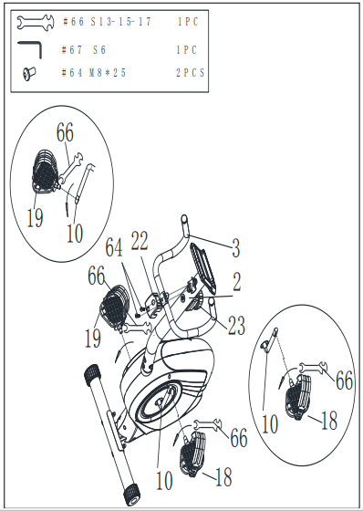
CAUTION: Please make sure the Tension Control Knob (No. 23) is at the highest resistance level (level 8, all the way to the right) before you connect the Tension Wire (No. 38).
Connect Tension Control Wire (No. 23a) and Tension Wire (No. 38). Then, pull Tension Control Wire (No. 23a) upward and insert it into the slot of metal bracket on Tension Wire (No. 38). Make sure the metal fitting on Tension Control Wire (No. 23a) is secured in the metal bracket.
Attach the Front Post (No. 2) onto the Main Frame (No. 1) using with 4 Hexagon Bolts (No. 59) and 4 Arc Washers (No. 54). Tighten and secure with the Allen Wrench (No. 67).
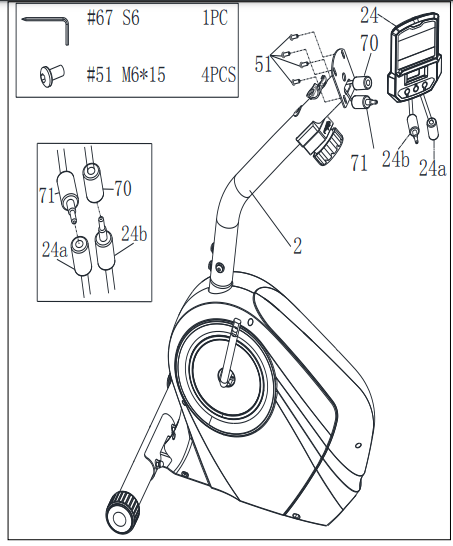
STEP 3: Remove 4 Cross Head Screws (No. 51) from the back of the Computer (No. 24) using Allen Wrench (No. 67).
Connect the Sensor Wire 2 (No. 70) and the Computer Wire B (No. 24b), connect the Sensor Wire 3 (No. 71) and the Computer Wire A (No. 24a).
Attach the Computer (No. 24) onto the Front Post (No. 2) with 4 Cross Head Screws (No. 51) that were removed. Tighten with Allen Wrench (No. 67)
STEP 4: WARNING! Read instructions carefully as improper assembly may cause permanent damage to your bike.
CAUTION: Please make sure the Tension Control Knob (No. 23) is at the highest resistance level (level 8, all the way to the right) before you assemble the Left & Right Pedals (No. 18 & No. 19).
Align the Left Pedal (No. 18) with the left side of the Crank (No. 10) at 90°. Turn the pedal bolt on Left Pedal (No. 18) counterclockwise as tightly as you can with your hand. Then, use Spanner (No. 66) to tighten and secure.
Align the Right Pedal (No. 19) with the right side of the Crank (No. 10) at 90°. Turn the pedal bolt on Right Pedal (No. 19) clockwise as tightly as you can with your hand. Then, use Spanner (No. 66) to tighten and secure.
Attach the Front Handlebar (No. 3) onto the Front Post (No. 2) with 2 Hexagon Bolts (No. 64). Tighten with Allen Wrench (No. 67). Then attach the Handlebar Cover (No. 22) onto Front Handlebar (No. 3)
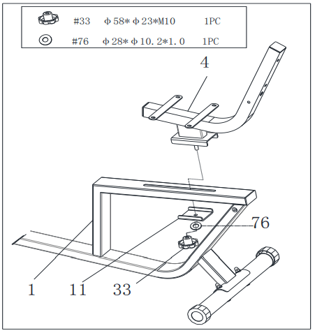
STEP 5: Loosen and remove the Adjustment Knob (No. 33), the Flat Washer (No. 76) and the Regulator (No. 11) from the Seat Post (No. 4).
Attach the Seat Post (No. 4) onto the Main Frame (No. 1) with 1 Regulator (No. 11), 1 Adjustment Knob (No. 33) and 1 Flat Washer (No. 76) that were removed.
Adjust the Seat Post (No. 4) to the desired position, then secure it in place by tightening the Adjustment Knob (No. 33).
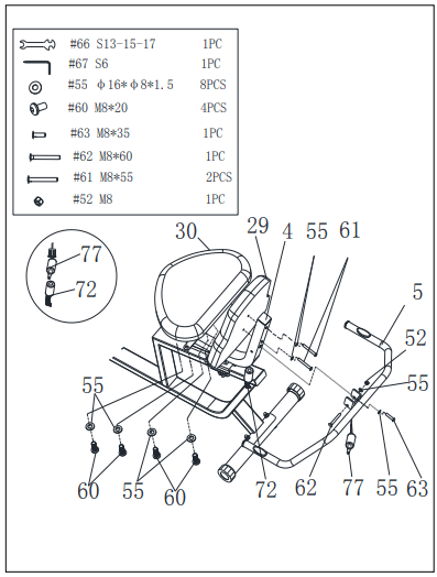
STEP 6: Attach the Seat (No. 30) onto the Seat Post (No. 4) with 4 Hexagon Bolts (No. 60) and 4 Flat Washers (No. 55). Tighten with Allen Wrench (No. 67).
Attach the Rear Handlebar (No. 5) onto the Seat Post (No. 4) with 2 Flat Washers (No. 55), 1 Hexagon Bolt (No. 63), 1 Cross Head Bolt (No. 62) and 1 Lock Nut (No. 52). Tighten with the Spanner (No. 66) and the Allen Wrench (No. 67).
Attach the Back Cushion (No. 29) onto the Seat Post (No. 4) with 2 Flat Washers (No. 55) and 2 Hexagon Bolts (No. 61). Tighten with the Allen Wrench (No. 67).
Lastly, connect the Sensor Wire 4 (No. 72) to the Sensor Wire 5 (No. 77).
MAINTENANCE & ADJUSTMENT GUIDE
ADJUSTING THE SEAT
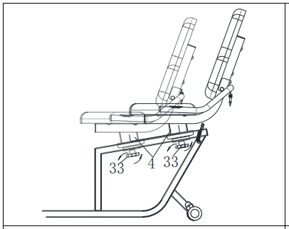
Turn the Adjustment Knob (No. 33) counter-clockwise to release Seat Post (No. 4) and then slide the Seat Post (No. 4) forward or backward to the desired position. Secure the Seat Post (No. 4) in place by turning the Adjustment Knob (No. 33) clockwise until tightened.
MOVING THE RECUMBENT BIKE
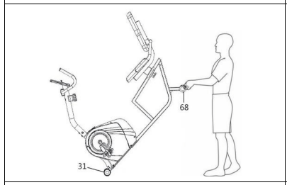
To move the recumbent bike, hold the Rear Stabilizer (No. 68) and tilt the recumbent bike until the End Caps (No. 31) located on the front stabilizer touch the ground. With the End Caps (No. 31) on the ground, you can transport the recumbent bike to the desired location with ease.
ADJUSTING THE BALANCE
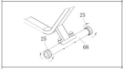
To achieve a smooth and comfortable ride, you must ensure that the recumbent bike is stabled and secured. If you notice the recumbent bike is unbalanced during use, adjust the End Caps (No. 25) located on the Rear Stabilizer (No. 68) until the recumbent bike becomes levelled with the floor surface.
ADJUSTING THE TENSION
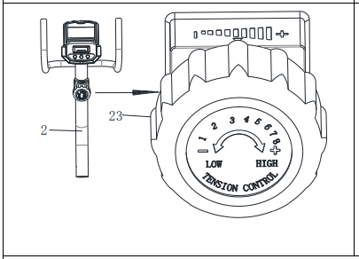
Adjust the tension by rotating the Tension Control Knob (No. 23) clockwise to increase the level of resistance. Rotate the Tension Control Knob (No. 23) counter-clockwise to decrease the level of resistance.
Tension levels are set at Level 1 being the lowest and Level 8 being the highest.
CLEANING
The recumbent bike can be cleaned with a soft, clean, damp cloth. Do not use abrasives or solvents on plastic parts. Please wipe your perspiration off the recumbent bike after each use. Be careful not get excessive moisture on the computer display panel as this might cause electrical hazards or electronics to fail.
Please keep the recumbent bike, especially the computer, out of direct sunlight to prevent screen damage.
Please inspect all assembly bolts and pedals on the recumbent bike for proper tightness every week.
STORAGE
Store the recumbent bike in a clean and dry environment, away from children.
BATTERY INSTALLATION AND REPLACEMENT
BATTERY INSTALLATION:
1. Take out 2 AAA batteries from computer box.
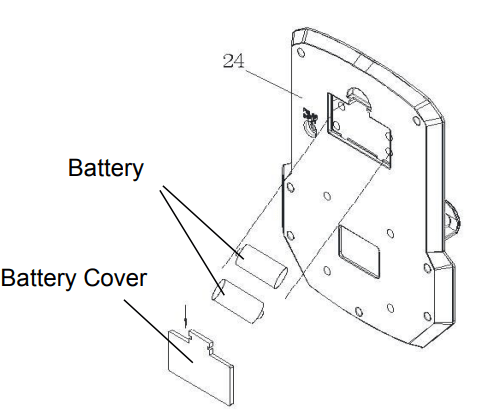
2. Press the buckle of battery cover on the back of the Computer (No. 24), then remove battery cover.
3. Install 2 AAA batteries into the battery case on the back of the Computer (No. 24). Pay attention to the battery + and – ends before installing.
4. Press the buckle of battery cover, then put the battery cover back to the back of the Computer (No. 24).
The installation is complete!
BATTERY REPLACEMENT:
1. Press the buckle of battery cover on the back of the Computer (No. 24), then remove battery cover.
2. Remove the 2 old AAA batteries in the battery case and install 2 new AAA batteries into the battery case on the back of the Computer (No. 24). Pay attention to the battery + and – ends before installing.
3. Press the buckle of battery cover, then put the battery cover back to the back of the Computer (No. 24).
The replacement is complete!
EXERCISE COMPUTER
FUNCTION BUTTONS:
MODE: Press the button to select TIME, DISTANCE, AND CAL to preset.
Press the button for selection function display value on LCD or enter after setting. Press the button and hold for 3 seconds to reset all values except odometer to zero.
(When user replaces the batteries, all the values will reset to ZERO automatically.)
SET: To set up the target value of TIME, DISTANCE, and CAL. Press the button and hold for 2 seconds to speed up the increment.
RESET: Press the button to reset function value when setting. Press the button and hold for 3 seconds to reset all values except odometer to zero.
(When user replaces the batteries, all the values will reset to ZERO automatically.)
FUNCTIONS & OPERATIONS:
1. BATTERY INSTALLATION: Please install 2 AAA 1.5V batteries in the battery case on the back of computer. (Whenever batteries are removed, all the function values will be reset to zero.)
2. AUTO ON/OFF: Once the user begins to exercise, the computer will show the workout value automatically. After about 4 minutes of inactivity, the computer will turn off. Odometer value does not reset to 0 when the computer turns off. When the user starts to exercise again, the workout value of odometer will accumulate continuously.
3. AUTO SCAN: After the computer is powered on, press Mode button and the LCD will display all function values from TIME-SPEED-DISTANCE-CALORIES-ODOMETER-PULSE. Each value will be shown for 6 seconds.
4. SPEED: Displays the current training speed from 0.0 to 99.9 MPH (miles per hour).
5. DISTANCE: Accumulates total distance from 0.00 up to 9999 M (miles). The user may preset target distance by pressing the SET & MODE button. Each increment is 0.1 M (miles). Automatically counts down from targeting value during exercise.
6. TIME: Accumulates total time from 00:00 up to 99:59. The user may preset target time by pressing SET & MODE button. Each increment is 1 minute. Automatically counts down from targeting value during exercise.
7. CALORIES: Accumulates calories burned during training from 0.0 to 9999 (Cal). The user may also preset the target calories before training by pressing SET & MODE button. Each setting increase is 1 Cal. Automatically counts down from targeting value during exercise.
NOTE: This data is a rough guide which cannot be used in medical treatment.
8. ODOMETER: Displays the total accumulated distance from 0 to 9999 M (miles). User can also press MODE button to display the odometer value.
9. PULSE: The computer will display user’s heart rate in beats per minute (BPM) during training.
10. RESET: Press the button and hold for 2 seconds to reset all values except odometer to zero.
TROUBLESHOOTING
PROBLEM
SOLUTION
There is no display on the computer console.
1. Remove the computer and verify that the wire from the computer is properly connected to the wire that comes from the front post.
2. Check if the batteries are correctly positioned and battery springs are in proper contact with batteries.
3. The batteries in the computer may be unresponsive. Change to new batteries.
The recumbent bike wobbles when in use.
Turn the end caps on the rear stabilizer as needed to level the recumbent bike.
The recumbent bike makes a squeaking noise when in use.
The bolts may have become loose on the recumbent bike. Please inspect all the bolts and tighten any loose bolts.