
0
PINK MAGNETIC RECUMBENT BIKE
P8400
USER MANUAL

1
IMPORTANT SAFETY INFORMATION
We thank you for choosing our product. To ensure your safety and health, please use this equipment
correctly. It is important to read this entire manual before assembling and using the equipment. Safe
and effective use can only be achieved if the equipment is assembled, maintained, and used properly.
It is your responsibility to ensure that all users of the equipment are informed of all warnings and
precautions.
1. Before starting any exercise program, you should consult your physician to determine if you have
any medical or physical conditions that could put your health and safety at risk or prevent you from
using the equipment properly. Your physician’s advice is essential if you are taking medication that
affects your heart rate, blood pressure, or cholesterol level.
2. Be aware of your body’s signals. Incorrect or excessive exercise can damage your health. Stop
exercising if you experience any of the following symptoms: pain, tightness in your chest, irregular
heartbeat, shortness of breath, lightheadedness, dizziness or feelings of nausea. If you do
experience any of these conditions, you should consult your physician before continuing with your
exercise program.
3. Keep children and pets away from the equipment. The equipment is designed for adult use only.
4. Use the equipment on a solid, flat level surface with a protective cover for your floor or carpet. To
ensure safety, the equipment should have at least 2 feet (60CM) of free space all around it.
5. Ensure that all nuts and bolts are securely tightened before using the equipment. The safety of the
equipment can only be maintained if it is regularly examined for damage and/or wear and tear.
6. Always use the equipment as indicated. If you find any defective components while assembling or
checking the equipment, or if you hear any unusual noises coming from the equipment during
exercise, discontinue use of the equipment immediately and do not use until the problem has been
rectified.
7. Wear suitable clothing while using the equipment. Avoid wearing loose clothing that may become
entangled in the equipment.
8. Do not place fingers or objects into the moving parts of the equipment.
9. The maximum weight capacity of this unit is 220 pounds (100 KG).
10. The equipment is not suitable for therapeutic use.
11. To avoid bodily injury and/or damage to the product or property, proper lifting and moving are
required.
12. Your product is intended for use in cool and dry conditions. You should avoid storage in extreme
cold, hot or damp areas as this may lead to corrosion and other related problems.
13. This equipment is designed for indoor and home use only; it is not intended for commercial use!
2
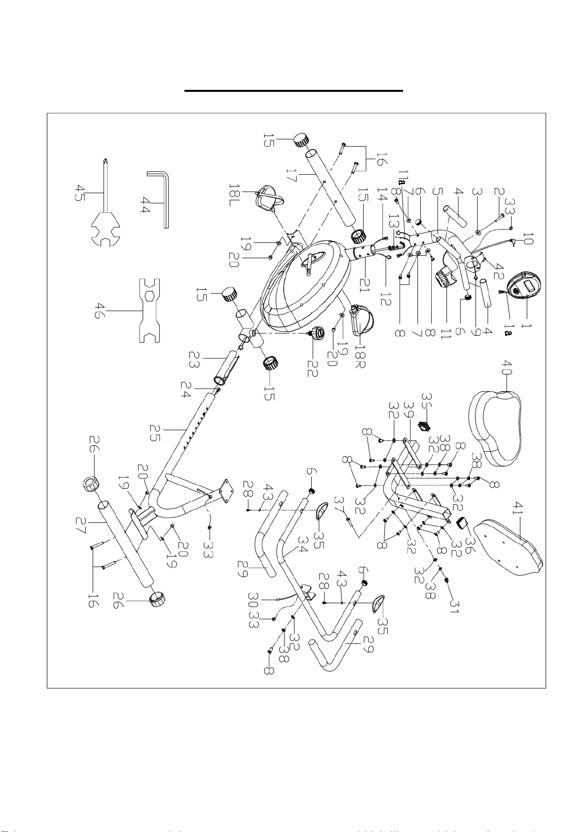
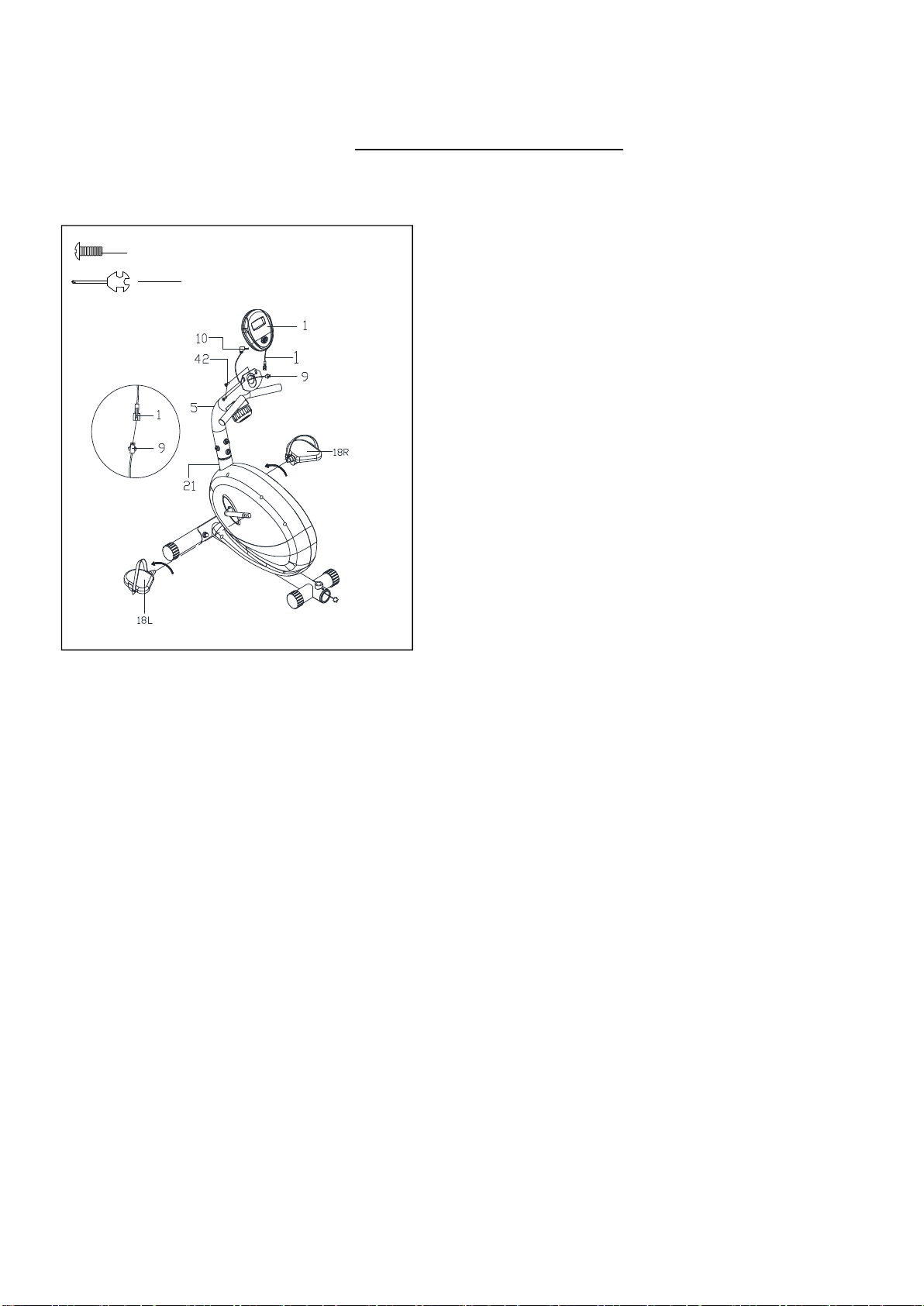
EXPLODED DIAGRAM 1
3
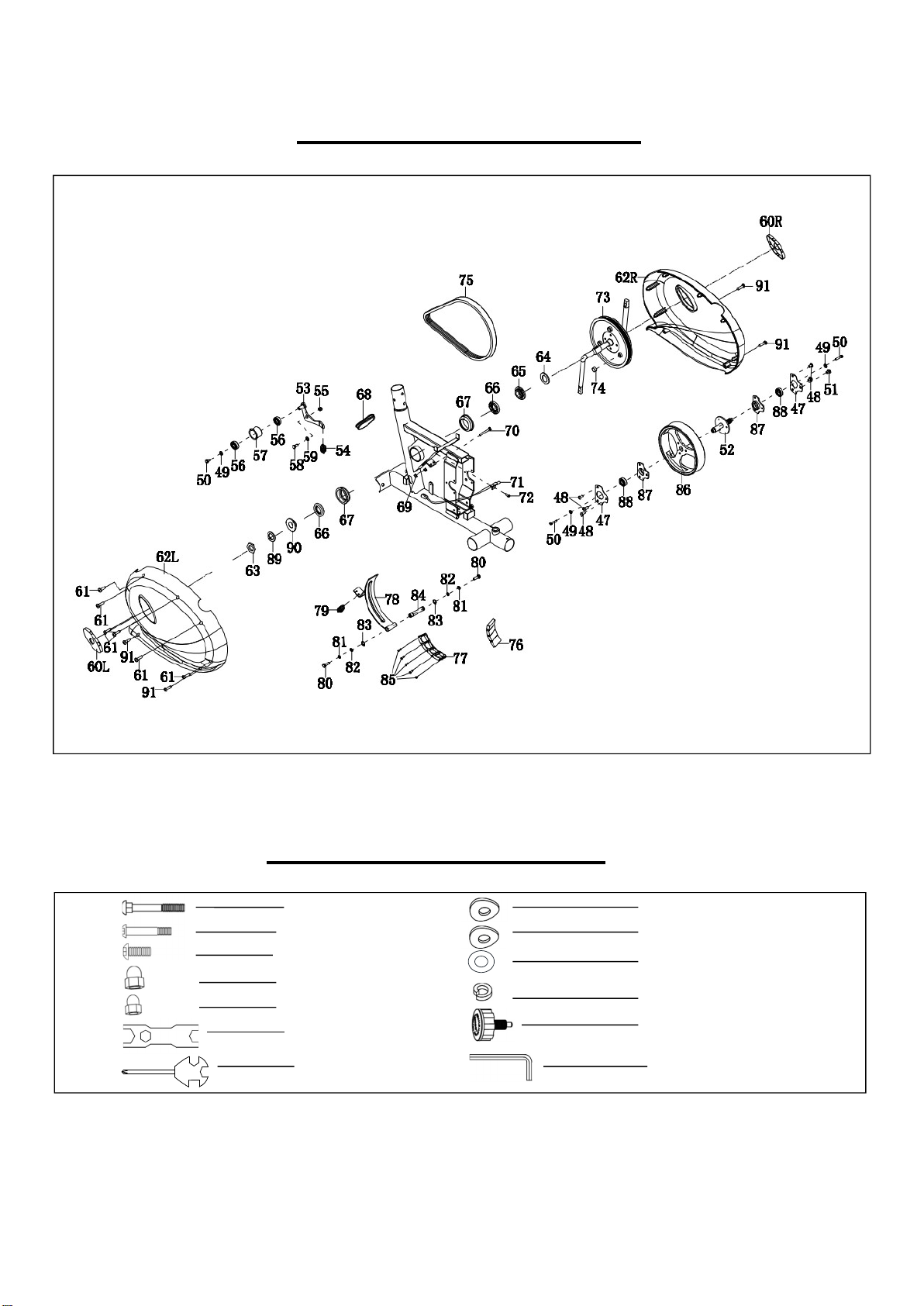
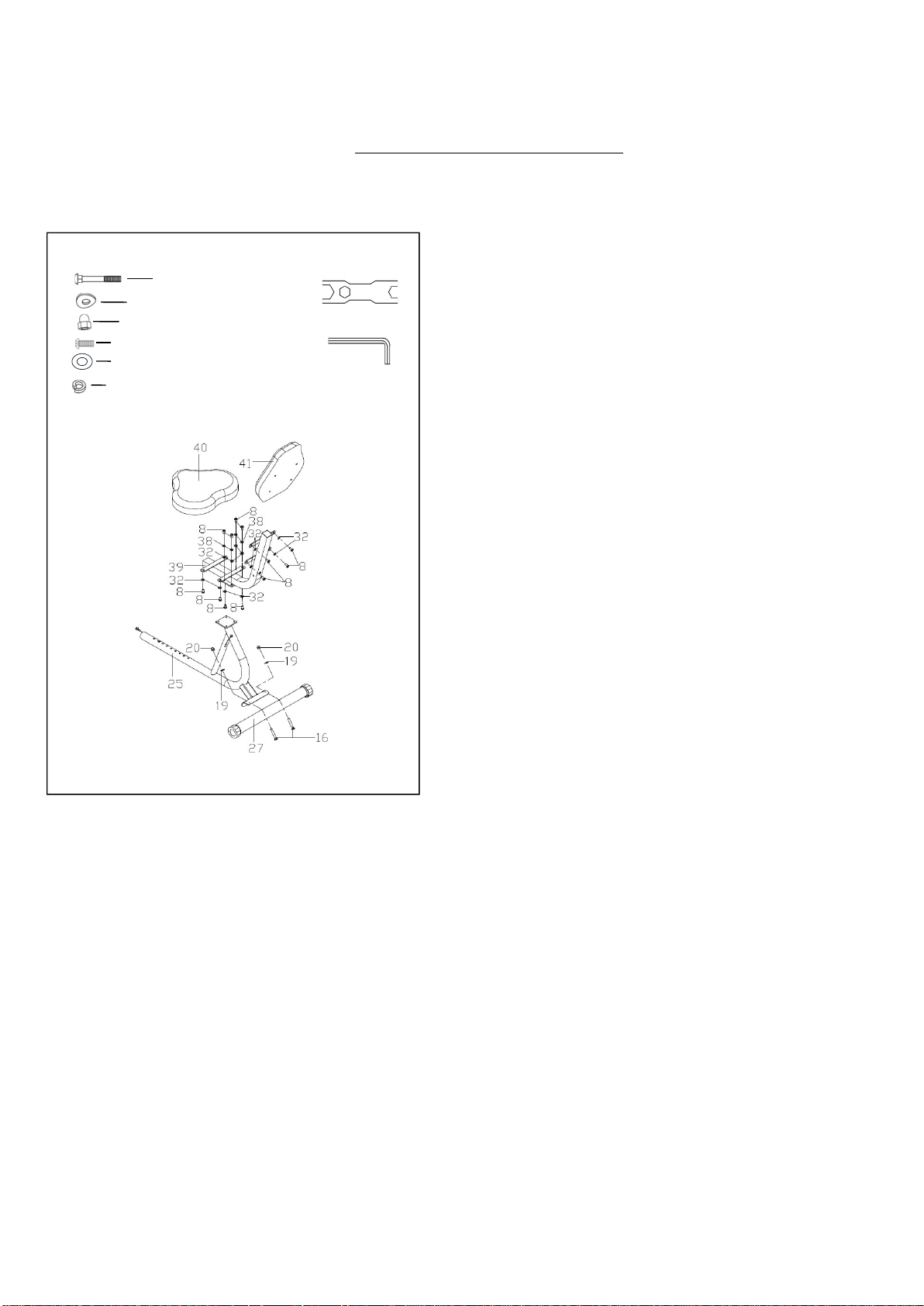
EXPLODED DIAGRAM 2
HARDWARE PACKAGE
#16 M10*60 4PCS #19 d10*Φ25*2*R30 4PCS
#37 M8*60 1PC
#7 d8*
Φ
20*2*R30 4PCS
#8 M8*16 5PCS
#32 d8*
Φ
16*1.5 2PCS
#20 M10 4PCS
#38 d8 2PCS
#31 M8 1PC
#22 M16*1.5*27 1PC
#46 S17
-
19 1PC
#45 S13
-
14
-
15 1PC
#44 S6 1PC

4
Ordering Replacement Parts (U.S. and Canadian Customers only)
Please provide the following information in order for us to accurately identify the part(s) needed:
The model number (found on cover of manual)
The product name (found on cover of manual)
The part number found on the “EXPLODED DIAGRAM” and “PARTS LIST” (found near the front of
the manual)
Please contact us at [email protected] or 1- 877 - 90SUNNY (877-907-8669).
No. Description Spec. Qty.
No. Description Spec. Qty.
1
Computer
1
46 Spanner
S17-19
1
1a Computer Wire
1
47 Fixing Plate
t1.5*56*72
2
2
Screw
M5*15
1
48
Screw
M6
*
10*
Φ
12
5
3 Arc Washer
d5*Φ20*1*R30
1
49 Washer
d6*Φ16*1.5
3
4
Foam Grip
Φ23*5*120
2
50
Bolt
M6
*
12*S10
3
5 Handlebar Post
1
51 Screw
M6*8*Φ12
1
6 End Cap
Φ25*16
4
52 Inertial Axle
1
7
Arc Washer
d8*Φ20*2*R30
4
53
Idler Connecting
Rod
1
8 Screw
M8*16
17
54 Spring
Φ2*Φ12*60*N20
1
9
Sensor Wire A
1
55
Nut
M8*H7.5*S13
1
10 Sensor Wire B
1
56 Bearing 6001-2RS CXSH
2
11 Tension Control Knob
1
57 Idler Wheel
1
11a Tension Control Cable
1
58 Screw
1
12 Sensor Wire C
1
59 Washer D12*Φ17*0.5 1
13 Tension Hook
1
60L/R
Crank Cap
2
14
Sensor Wire D
1
61
S
crew
S
T4.2*19*
Φ
8
6
15 End Cap
Φ50
4
62L/R
Belt Cover
2
16 Bolt
M10*60
4
63 Hex Nut
1
17
Front Stabilizer
1
64
Locking Washer
D26*
Φ
38*1
1
18L/R
Pedal L/R
2
65 Locking Nut-Right 1
19 Arc Washer
d10*Φ25*2*R30
4
66 Open Face Bearing 2
20 Nut
M10
4
67 Bearing Housing 2
21
Main Frame
1
68
Cap
1
22 Knob
M16*1.5*27
1
69 Nut M6*H5*S10 2
23 Bushing
Φ50
1
70 Bolt M6*45*S10 1
24 Sensor Wire E
1
71 Sensor Seat 1
25 Rear Main Frame
1
72 Screw ST4.2*10*Φ8 1
26 End Cap Φ50 2
73 Crank with Belt Wheel 1
27 Rear Stabilizer
1
74 Round Magnet 1
28 Screw
ST4*19
2
75 Belt 1
29 Foam Grip
Φ23*5*500
2
76 Square Magnet 40*25*10 4
30 Handle Pulse Wire
1
77 Magnet Locator 1
31 Nut
M8
1
78 Magnetic Board 1
32
Washer
d8*Φ16*1.5
14
79
Spring
Φ
1.5*
Φ
15*41*N8
1
33 Grommet Φ12*Φ11*3 3
80 Bolt M6*16*S10 2
34 Handlebar
1
81 Spring Washer D6 2
35 Hand Pulse Sensor
2
82 Washer D6*Φ12*1.2 2
36
End Cap
F38*38*1.5
2
83
C Clip
D12
2
37 Bolt
M8*60
1
84 Axle for Magnetic Board 1
38 Spring Washer d8 6
85 Screw ST3*10*Φ5.6 5
39 Backrest Frame
1
86 Inertial Wheel 1
40 Seat Cushion
1
87 Bearing Seat 2
41
Backrest Cushion
1
88
Bearing
6001
-
2RS C&U
2
42 Screw M5*10 2
89 Locking Washer 1
43 Washer d6*Φ12*1 2
90 Locking Nut-Left 1
44 Allen Wrench S6 1
91 Screw ST4.2*20 4
45 Spanner S13-14-15 1
PARTS LIST
5
ASSEMBLY INSTRUCTIONS
We value your experience using Sunny Health and Fitness products. For assistance with parts or
troubleshooting, please contact us at support@sunnyhealthfitness.com or 1-877-90SUNNY (877-907-
8669).
S
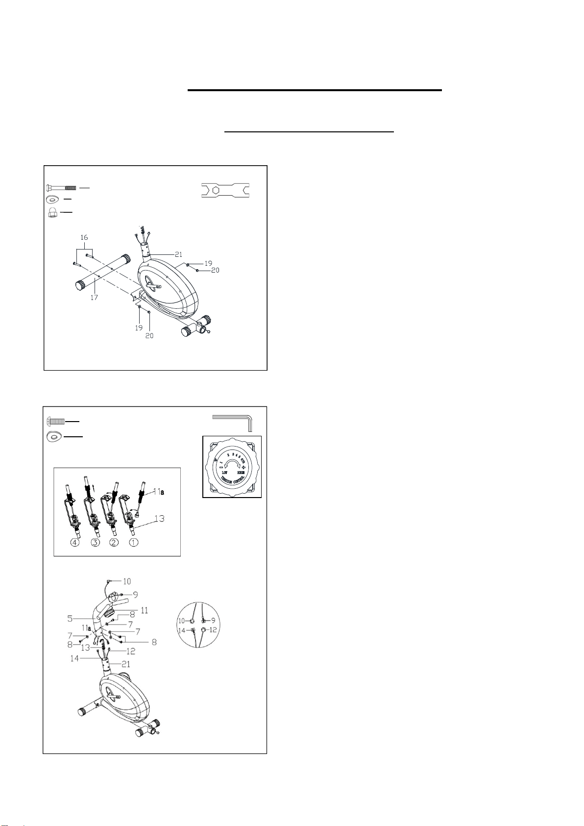
TEP 1:
Secure Front Stabilizer (No. 17) to Main Frame
(No. 21) with 2 Bolts (No. 16), 2 Arc Washers
(No. 19), and 2 Nuts (No. 20). Tighten and
secure with Spanner (No. 46).
STEP 2:
NOTE: Turn the Tension Control Knob (No. 11)
all the way to the left (the lowest level of
resistance). This provides the tension cable with
the longest length required to connect the wires.
(See diagram C)
Connect Sensor Wire A (No. 9) with Sensor
Wire C (No. 12). Then connect Sensor Wire B
(No. 10) with Sensor Wire D (No. 14). (See
diagram A to the left)
Connect Tension Hook (No. 13) with Tension
Control Cable (No. 11a). (See diagram B)
Secure Handlebar Post (No. 5) to Main Frame
(No. 21) with 4 Screws (No. 8) and 4 Arc
Washers (No. 7). Tighten and secure with Allen
Wrench (No. 44).
#16 M10*60 2PCS
#19 d10*Φ25*2*R30 2PCS
#46 S17-19 1PC
#20 M10 2PCS
#8 M8*16 4PCS
#7 d8*Φ20*2*R30 4PCS
#44 S6 1PC
A
B
C
A
6
We value your experience using Sunny Health and Fitness products. For assistance with parts or
troubleshooting, please contact us at [email protected] or 1-877-90SUNNY (877-907-
8669).
a
a
STEP 3:
Remove 2 preassembled Screws (No. 42) from
the back of the Computer (No. 1) with Spanner
(No. 45). Connect Computer Wire (No. 1a) with
Sensor Wire A (No. 9), then secure Computer
(No. 1) to Handlebar Post (No. 5) with 2 Screws
(No. 42) that were removed. Tighten and secure
with Spanner (No. 45). Insert Sensor Wire B
(No. 10) into the hole on the back of Computer
(No. 1).
Secure Pedals (No. 18L/R) onto the left and right
crank of Main Frame (No. 21).
CAUTION: The left side of the recumbent bike
has reversed threading. You must screw the left
pedal counter-clockwise to tighten. The right
pedal is tightened by turning clockwise. Failure to
follow these instructions can result in permanent
damage to your bike.
#42 M5*10 2PCS
#
45
S13
-
14
-
15
1PC
7
We value your experience using Sunny Health and Fitness products. For assistance with parts or
troubleshooting, please contact us at support@sunnyhealthfitness.com or 1-877-90SUNNY (877-907-
8669).
STEP 4:
Secure the
Rear Stabilizer (No. 27)
to the
Rear
Main Frame (No. 25), with 2
Bolts (No. 16), 2
Arc
Washers (No. 19), and 2
Nuts (No. 20). Tighten
and secure with
Spanner (No. 46)
Remove
4
Screws
(No.
8),
4
Spring
Washers
(No. 38),
and
4
Washers (No. 32)
from
Rear Main
Frame (No. 25)
with
Allen Wrench (No. 44).
Secure
Backrest
Frame
(No.
39)
to
Rear
Main
Frame (No. 25)
with 4
Screws (No. 8), 4
Spring
Washers (No. 38),
and 4
Washers (No. 32)
that
were
removed.
Tighten
and
secure
with
Allen
Wrench (No. 44).
For easier installation of the next step, try flipping
Rear Main Frame (No. 25)
over.
Remove
8
Screws
(No.
8)
and
8
Washers
(No.
32)
from
Seat
Cushion
(No.
40)
and
Backrest
Cushion (No. 41)
with
Allen Wrench (No. 44).
Secure
Seat
Cushion
(No.
40)
and
Backrest
Cushion
(No.
41)
to
Backrest
Frame
(No.
39)
with
8
Screws
(No.
8)
and
8
Washers
(No.
32)
that were removed. Tighten and secure with
Allen
Wrench (No. 44).
#16 M10*60 2PCS
#19 d10*Φ25*2*R30 2PCS
#20 M10 2PCS
#8 M8*16 12PCS
#32 d8*Φ16*1.5 12PCS
#38 d8 4PCS
#46 S17-19 1PC
#44 S6 1PC
8
We value your experience using Sunny Health and Fitness products. For assistance with parts or
troubleshooting, please contact us at support@sunnyhealthfitness.com or 1-877-90SUNNY (877-907-
8669).
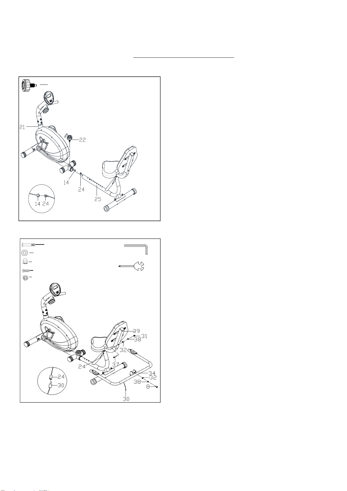
STEP 5:
Connect Sensor Wire D (No. 14) with Sensor
Wire E (No. 24), then secure the Rear Main
Frame (No. 25) to the Main Frame (No. 21) with
the Knob (No. 22).
NOTE: There are different holes on the Rear Main
Frame (No. 25) which can be used for people with
different height. You can find the best position hole
for your height. With feet at the extended position,
your knee should bend at 15 degrees.
STEP
6
:
Secure Handlebar (No. 34) to Backrest Frame
(No. 39) with 1 Bolt (No. 37), 1 Screw (No. 8), 2
Spring Washers (No. 38), 2 Washers (No. 32),
and 1 Nut (No. 31). Tighten and secure with Allen
Wrench (No. 44) and Spanner (No. 45).
Connect Sensor Wire E (No. 24) with Handle
Pulse Wire (No. 30).
The assembly is complete!
#22 M16*1.5*27 1PC
#37 M8*60 1PC
#
32 d8*
Φ
16*1.5 2
PCS
#31 M8 1PC
#
8
M8*16 1
PC
#
38
d8 2
PCS
#44 S6 1PC
#45 S13-14-15 1PC
9
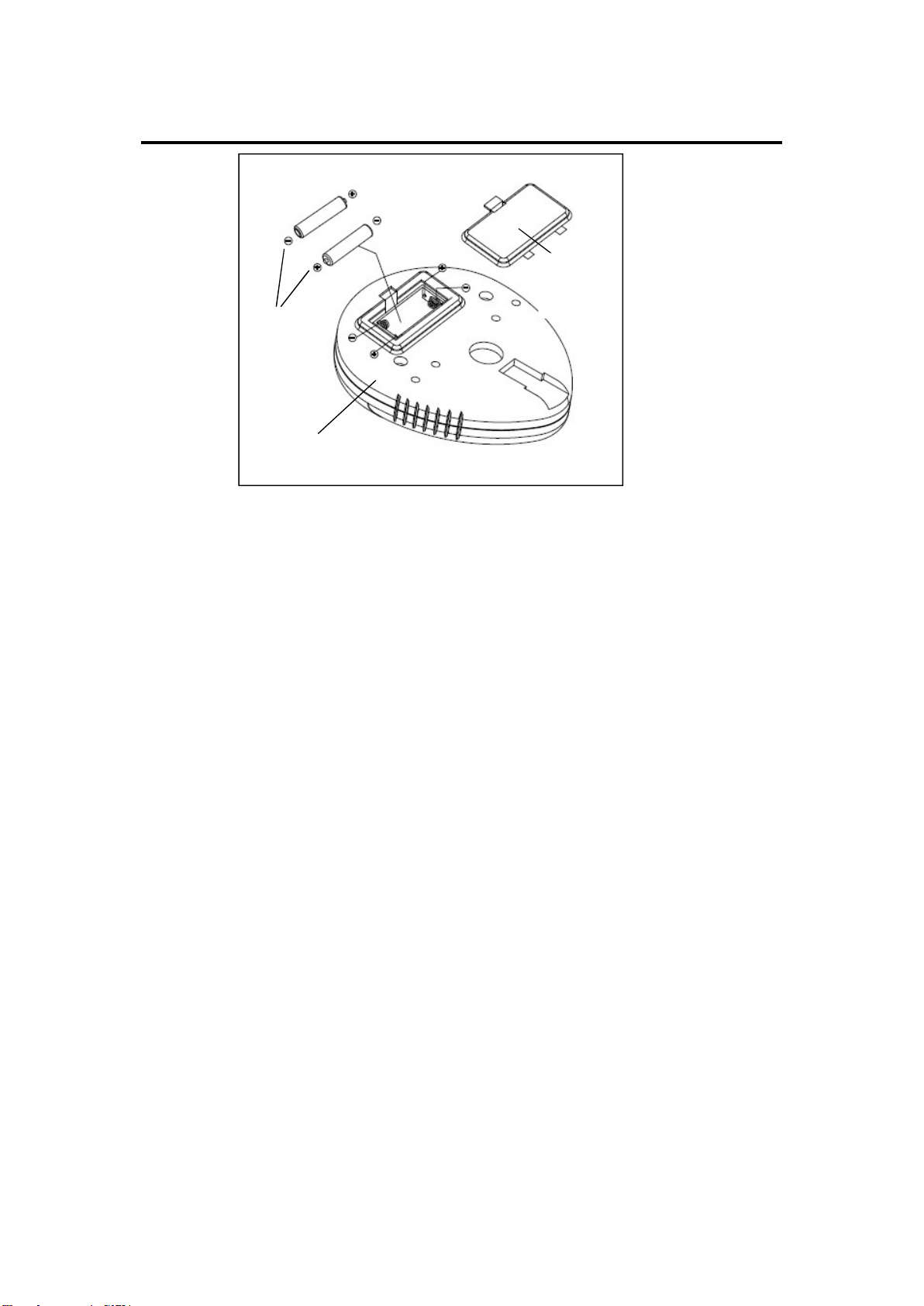
BATTERY INSTALLATION & REPLACEMENT
BATTERY INSTALLATION
1. Take out 2 AAA batteries from computer box.
2. Press the buckle of battery cover on the back of the Computer (No. 1), then remove battery cover.
3. Install 2 AAA batteries into the battery case on the back of the Computer (No. 1). Pay attention to
the battery + and – poles before installing.
4. Press the buckle of battery cover, then put the battery cover back to the back of the Computer (No.
1).
The installation is complete!
BATTERY REPLACEMENT
1. Press the buckle of battery cover on the back of the Computer (No. 1), then remove battery cover.
2. Remove the 2 old AAA batteries in the battery case and install 2 new AAA batteries into the battery
case on the back of the Computer (No. 1). Pay attention to the battery + and – poles before
installing.
3. Press the buckle of battery cover, then put the battery cover back to the back of the Computer (No.
1).
The replacement is complete!
BATTERY DISPOSAL:
Dispose the batteries according to the laws and regulations of your local region. Some batteries may
be recycled. When disposing or recycling, do not mix battery types.
Battery
1
Battery
Cover

10
EXERCISE COMPUTER
FUNCTION BUTTONS:
MODE: Press to select functions.
Press and hold the MODE button for 3 seconds to reset time, distance, and calories.
SET: Press to set values of time, pulse, distance, and calories when not in scan mode.
Press the MODE button to cycle through functions: time, distance, and calories to select desired
function. Use the SET button to set a value for time, distance, or calories. The value of a function will
be set on a countdown. Press the MODE button once more, to save the function value you’ve created.
RESET: Press to reset time, pulse, distance, and calories to zero when not in scan mode.
OPERATION FUNCTIONS:
SCAN: Press MODE button until “▼” appears at SCAN position (or until “SCAN” appears), the
computer will rotate through all 5 functions: Time, Speed, Distance, Calories, and Total Distance. Each
display will be held for 6 seconds.
TIME: Counts the total time of the exercise from start to finish.
SPEED: Displays the current speed.
DISTANCE (DIST): Counts the distance of an exercise from start to finish.
CALORIES (CAL): Counts the number of total calories burned during an exercise from start to finish.
TOTAL DISTANCE (ODO): Counts the total distance after installing the batteries.
AUTO ON/OFF & AUTO START/STOP: If the wheel is in motion or if any button is pressed, the
computer will become active and shall remain active until it’s been inactive for 8 minutes. Then, the
power (computer) will turn off automatically.
PULSE RATE: Press MODE button until “▼” appears at PULSE position, (or until “ ” appears). To
properly measure your pulse rate, you must place both your palms on the hand pulse sensors located
on the handlebar next to the seat.
Remark: During the process of pulse measurement, the measurement value may be higher than virtual
pulse rate during the first 2~3 seconds, after which it will return to normal level. To ensure testing
accuracy, it is suggested that user test pulse during stop/pause exercise to avoid any possible influence.
The measurement value cannot be regarded as the basis of medical treatment.
ALARM: The functions of time, distance, and calories can be set to countdown, if any of the above
value goes to zero, the computer will beep for 15 seconds.
Press MODE to select the function, then press SET to adjust the value.

11
SPECIFICATIONS:
FUNCTION
Auto Scan
Every 6 seconds
Running Time 00:00 ~ 99:59(Minute: Second)
Current Speed
The max pick-up signal is 999.9 MILES/H (or
9999RPM)
Trip Distance 0.0 ~ 999.9 MILES
Calories 0 ~ 9999 KCAL
Total Distance
0 ~ 9999 MILES
Pulse Rate 40-240BPM
Battery Type 2 pcs of SIZE- AAA
Operating Temperature 0°C ~ +40°C (32°F ~104°F)
Storage Temperature -10°C ~ +60°C (14°F ~140°F )
Version 1.
1
2

12
