Ordering Replacement Parts (U.S. and Canadian Customers only)
Please provide the following information in order for us to accurately identify the part(s) needed:
✓ The model number (found on cover of manual)
✓ The product name (found on cover of manual)
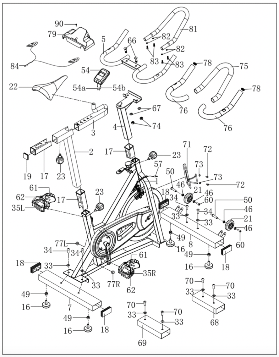
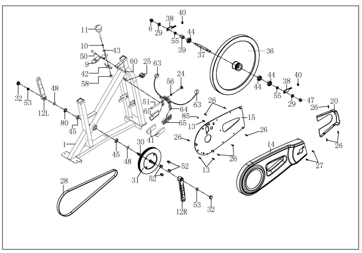
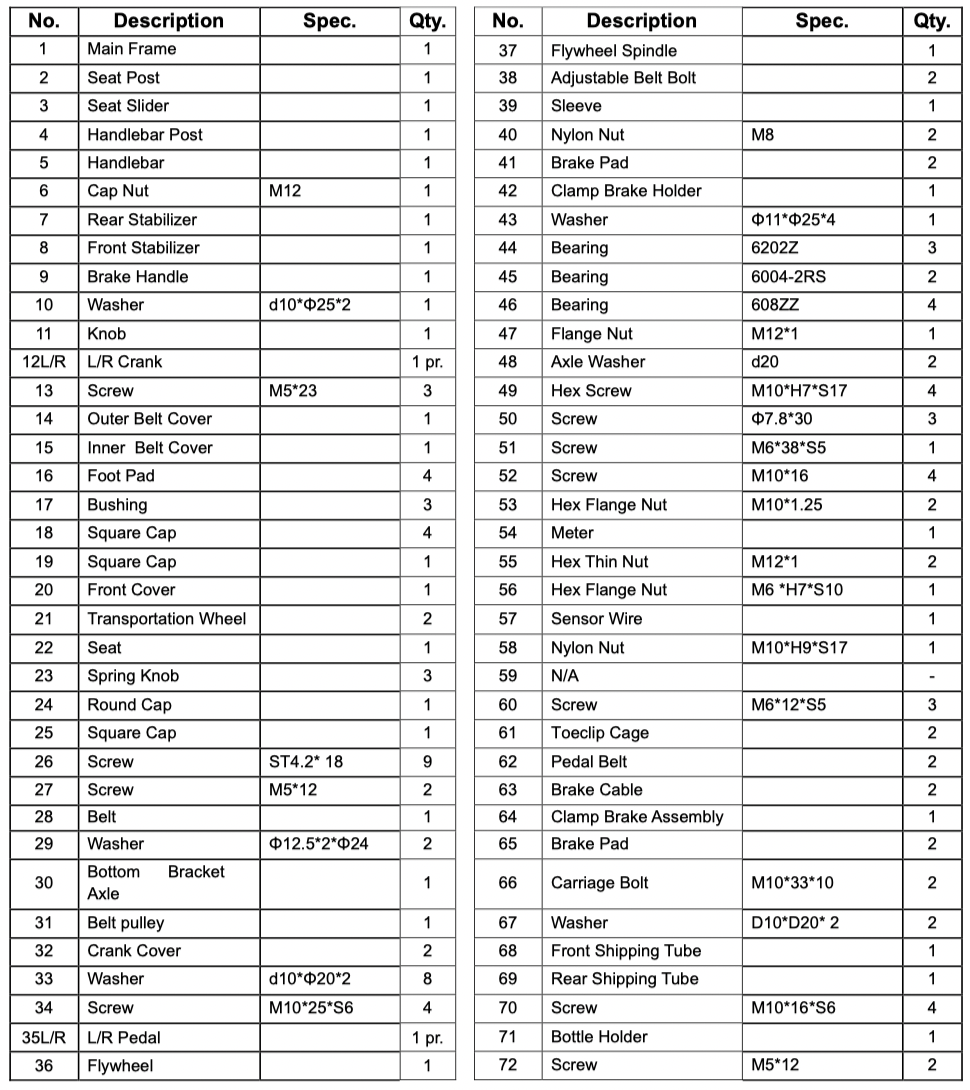
✓ The part number found on the “EXPLODED DIAGRAM” and “PARTS LIST” (found near the front of the manual)
Please contact us at sunnyhealthfitness or 1 - 877 - 90SUNNY (877-907-8669).
ASSEMBLY INSTRUCTIONS
We value your experience using Sunny Health and Fitness products. For assistance with parts or troubleshooting, please contact us at supportsunnyhealthfitness or 1-877-90SUNNY (877-9078669).
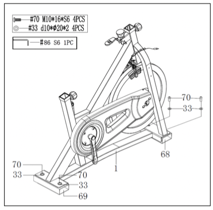
STEP 1:
Use Allen Wrench (No. 86) to unscrew 4 Screws (No. 70) and 4 Washers (No. 33) from Front & Rear Shipping Tubes (No. 68 & No. 69). Then remove and discard the Front & Rear Shipping Tubes (No. 68 & No. 69).
OPTIONAL: You may save these parts: Screws (No. 70), Washers (No. 33), Front & Rear Shipping Tubes (No. 68 & No. 69) for future packaging and transportation of bike.
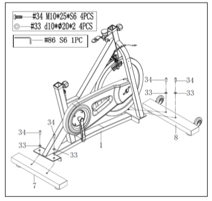
STEP 2:
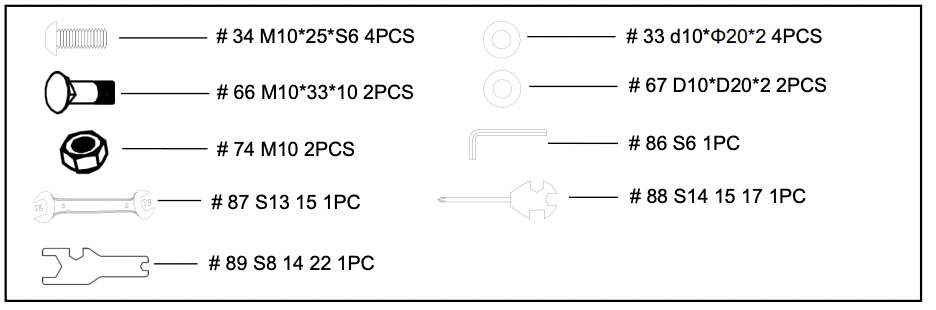
Attach the Front & Rear Stabilizers (No. 8 & No. 7) to the Main Frame (No. 1) using 4 Screws (No. 34) and 4 Washers (No. 33). Tighten and secure with Allen Wrench (No. 86).
STEP 3:
IMPORTANT! Read instructions carefully, failure to do so may cause permanent damage to your bike.
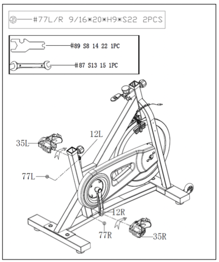
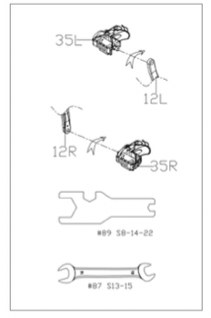
Remove the Left & Right Nylon Nuts (No. 77L/R) located on the Pedals (No. 35L/R). The Right Nylon Nut (No. 77R) is white on the inside. The Left Nylon Nut (No. 77L) is blue on the inside. The Pedals (No. 35L/R) are marked L and R.
Screw the Left Pedal (No. 35L) COUNTERCLOCKWISE into the Left Crank (No. 12L). Once properly screwed into place, use the Wrench (No. 87) to hold the bolt of the pedal and screw the Left Nylon Nut (No. 77L) CLOCKWISE to the thread end of the Left Pedal (No. 35L) securely with Spanner (No. 89).
Screw the CLOCKWISE Right Pedal (No. 35R) into the Right Crank (No. 12R). Once properly screwed into place, use the Wrench (No. 87) to hold the bolt of the pedal and screw the Right Nylon Nut (No. 77R) COUNTER-CLOCKWISE to the thread end of the Right Pedal (No. 35R) securely with Spanner (No. 89).
STEP 4:
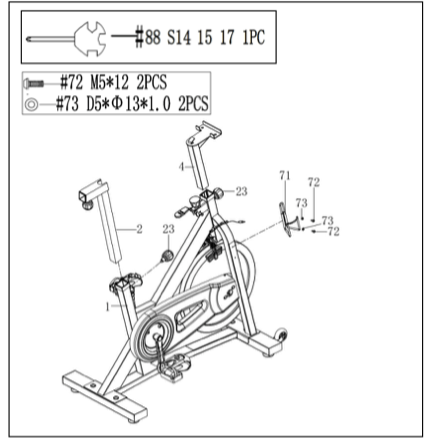
Loosen and remove 2 Spring Knobs (No. 23). Insert the Seat Post (No. 2) and Handlebar Post (No. 4) into the sleeves located on the Main Frame (No. 1). Adjust the Seat Post (No. 2) and Handlebar Post (No. 4) to the desired positions. Re-insert and tighten the 2 Spring Knobs (No. 23) to secure the Seat Post (No. 2) and Handlebar Post (No. 4) in place.
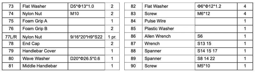
Remove the preassembled 2 Screws (No. 72) and 2 Flat Washers (No. 73) from Main Frame (No. 1). Then attach the Bottle Holder (No. 71) to Main Frame (No. 1) using the 2 Screws (No. 72) and 2 Flat Washers (No. 73) that were just removed. Tighten and secure with Spanner (No. 88).
STEP 5
NOTE: In order to properly tighten the seat, it is important to note that you will need two open faced wrenches (1 for each side) and will need to tighten the nut on each side simultaneously working in opposite directions of each other.
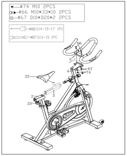
Loosen and remove the Spring Knob (No. 23). Next, insert the Seat Slider (No. 3) into the Seat Post (No. 2) and adjust it to the desired position. Re-insert and tighten Spring Knob (No. 23) to secure the Seat Slider (No. 3) in place.
Attach the Seat (No. 22) to the Seat Slider (No. 3). Tighten and secure with Wrench (No. 87).
Attach the Handlebar (No. 5) to the Handlebar Post (No. 4) using 2 Carriage Bolts (No. 66), 2 Washers (No. 67) and 2 Nylon Nuts (No. 74). Tighten and secure with Spanner (No. 88).
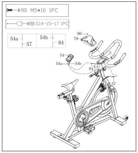
STEP 6:
Remove the preassembled Screw (No. 90) from Handlebar (No. 5). Then attach Handlebar Cover (No. 79) to Handlebar (No. 5) using the Screw (No. 90) that were just removed. Tighten and secure with Spanner (No. 88).
Connect Pulse Wire (No. 84) and Sensor Wire (No. 57) to the relative wires of Meter (No. 54). Then insert the Meter (No. 54) to the bracket of the Handlebar Post (No. 4).
The assembly is complete!
ADJUSTMENT GUIDE
ADJUSTING THE BALANCE:
In order to achieve a smooth and comfortable ride during use, you must ensure the stability of the bike. If you notice that the bike is unbalanced, you can adjust the foot pads located beneath the front and rear stabilizers. To do so, use the Spanner (No. 88) to loosen the Hex Screw (No. 49) by turning it clockwise (direction A). With the nut loosened, rotate the Foot Pad (No. 16) until it sits level with the surface that the bike is on. When you have finished adjusting the foot pad, re-tighten the Hex Screw (No. 49) by turning it counter-clockwise (direction B) using Spanner (No. 88). If required, repeat this process to adjust the remaining foot pads.
RESISTANCE AND BRAKING:
You may adjust the tension level of the bike by rotating the Knob (No. 11). To increase the level of resistance, rotate the knob clockwise. To decrease the level of resistance, rotate the knob counter-clockwise.
During an exercise, you may stop the bike immediately by pushing down on the Brake Handle (No. 9). This is the emergency brake.
ADJUSTING THE HANDLEBAR:
It is important that the handlebar and seat are both set to the correct height of your body. To adjust the handlebar height, loosen and pull the Spring Knob (No. 23) outward, then slide the Handlebar Post (No. 4) up or down to the desired height. Once adjusted re-insert and tighten the Spring Knob (No. 23) to secure the Handlebar Post (No. 4) in place.
TRANSPORTING THE BIKE:
To move the bike, first ensure that the Handlebar (No. 5) is properly secured. If the Handlebar (No. 5) is loose, tighten the Spring Knob (No. 23) to secure it. Next, stand at the front of the bike so that you’re directly in front of the Handlebar (No. 5). Firmly grasp and hold each side of the Handlebar (No. 5), place one foot on the front base and tilt the bike towards you until the transportation wheels on the front base touch the ground. With the wheels on the ground, you can transport the bike to the desired location with ease.
NOTE: When moving the bike, always use caution as unexpected impact, such as dropping the bike, may cause injury and affect the bike’s performance.
PEDAL STRAP ADJUSTMENT
Your feet should be secured in the toe clips during exercise. Place your feet as far forward into the toeclips as you can. With your feet in place, turn the crank to bring one foot to within arm’s reach, grasp the Pedal Belt (No. 62) and pull it upward to tighten the Toe-clip Cage (No. 61). Next, insert the Pedal Belt (No. 62) back into the hoop of the toe-clip. Repeat this process to secure your other foot.
ADJUSTING THE SEAT
The seat of this bike is fully adjustable as it moves Up, Down, Fore (forward), Aft (backward).
To adjust the height of the Seat Post (No. 2), loosen and pull the [seat post] Adjustment Knob (No. 23) outward, then raise or lower the seat to the desired height. Once adjusted, re-insert and tighten the [seat post] Adjustment Knob (No. 23) to secure the seat in place.
To adjust the seat back and forth, loosen and pull [seat slider] Adjustment Knob (No. 23) outward, then slide the Seat Slider (No. 3) to the desired position. Once positioned, re-insert and tighten the [seat slider] Adjustment Knob (No. 23) to secure the seat slider tube in place.
CHECKING BRAKE PADS AND PEDALS
Ensure all the Nuts, Nut Caps and Pedals are secured and inspect the equipment regularly. If you should find any defective parts, do not exercise until they’ve been repaired.
Pay close attention to easily damaged parts due to wear and tear. Please inspect Brake Pads (No. 41) to ensure there is still adequate padding on each side before exercising. Make sure to replace brake pads as necessary. Inspect the pedals before exercise. If they have become loose, please re-tighten.
TIGHTENING THE SEAT
Please adjust the Hexagon Nuts by using the Wrench (No. 87) if the Seat (No. 22) is loose.
NOTE: In order to properly tighten the Seat (No. 22), it is important to note that you will need two open faced wrenches (1 for each side) and will need to tighten the nut on each side simultaneously working in opposite direction of each other.
MAINTENANCE INSTRUCTIONS
This is general information for daily, weekly and monthly maintenance to be performed on your bike.
DAILY MAINTENANCE
After each exercise session, wipe down all the equipment: seat, frame and handlebars. Pay special attention to the seat post, handlebar post and belt/chain guard. Sweat is very corrosive and may cause problems that require parts replacement later.
1. Get on the bike and engage the drive train.
2. Pay attention to any vibrations felt through the pedals. If you feel any vibrations, you may need to tighten the pedals, bottom bracket, or adjust the drive belt/chain tension.
3. Use a wrench to tighten the pedals until they are secure.
WEEKLY MAINTENANCE
1. Inspect moving parts and tighten the hardware.
2. Inspect pull pin frame fittings, making sure the fittings are snug. Loose frame fittings may strip out threads over time and cause extensive damage.
3. Clean and lubricate pop pin assemblies. Pull on the pin and spray a small amount of lubricant onto the shaft.
4. Tighten the seat hardware, making sure the seat is level and centered.
5. Brush and treat the resistance pads. Remove any foreign material that may have collected on the pads. Spray the pads with silicone lubricant. This helps to reduce noise from friction between the pads and the flywheel.
6. Visually inspect the bottom bracket, toe clips and toe straps. If any of them are loose or disconnected, attach and tighten.
MONTHLY MAINTENANCE
1. Check all hardware is secure, such as: bottle holder, flywheel nuts, belt/chain guard bolts, brake caliper lock nuts and brake caliper tension rod nuts.
2. Inspect the brake tension rod for signs of wear such as missing threads. Clean and lubricate the brake tension rod.
3. Clean and lubricate the seat post, handlebar post and seat slider. Remove any buildup of foreign material.
LEATHER BRAKE PAD CARE (If Applicable)
1. Perform this maintenance when the brake pad is first installed and for the life of the brake pad. Following these simple guidelines can increase the life of your brake pads.
2. Some brake pad assemblies are prelubricated. Squeeze the brake pad. If lubricant is released, then the pad has been pre-lubricated.
3. If the brake pad is dry, then coat the brake pad with 3-n-1 oil. Brush the leather with a clean, wire bristle brush, and then apply the oil. The oil should be allowed to soak into the pad. Repeat 4-5 times until the pad is saturated, but not dripping with oil. When the pad is saturated, it will no longer absorb oil.
4. Inspect the brake pad weekly and lubricate if needed. The pad should not have a glazed appearance. If the pad appears glazed, then brush it with wire brush and apply lubricant as needed. If any of the sponge padding is showing through the leather pad, the brake pad should be replaced.
BATTERY INSTALLATION & REPLACEMENT
BATTERY INSTALLATION
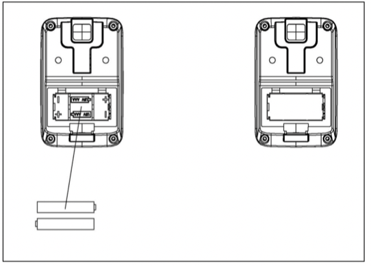
The meter uses 2 AAA batteries. Open the battery cover from the back of meter, then put 2 batteries into the battery compartment. Make sure the (+) and (-) ends of the batteries are in the correct position. Put the battery cover back.
BATTERY REPLACEMENT
If there is a problem with the display, try changing the batteries first. Open the battery cover, remove the old batteries, and replace with new batteries. Make sure the (+) and (-) ends of the batteries are in the correct position. Put the battery cover back. When changing batteries, always replace both with new batteries. Do not mix old and new batteries. Dispose the batteries according to the laws and regulations of your local region.
EXERCISE METER
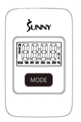
FUNCTION BUTTONS MODE:
1. Press the button for selection function display value on the meter.
2. Press the button and hold for 2 seconds to reset all values except odometer to zero.
Note: When the user replaces batteries, all the values will reset to ZERO automatically.
OPERATIONS:
AUTO ON/OFF: The meter will show the workout value automatically as the user begins to exercise. When the bike is inactive over 4 minutes, the meter will turn off and the workout value on the odometer will be held. When the user starts the exercise again, the workout value on Odometer will accumulate continuously.
AUTO SCAN: After the meter is powered on or the Mode button is pressed, it will display all function values: TIME-SPD-DST-CAL-ODO-RPM-PUL (repeat). Every function will display for 6 seconds.
FUNCTIONS:
SPD (SPEED): Displays the current speed being obtained. The range is from 0.0 to 99.9 MPH (Mile per Hour).
DST (DISTANCE): Counts the total distance of an exercise from start to finish. The range is from 0.00 up to 9999 M (Mile).
TMR (TIME): Counts the total time of an exercise from start to finish. The range is from 00:00 up to 99:59.
CAL (CALORIES): Counts the total amount of calories burned during an exercise from start to finish. The range is from 0.0 to 9999 KCAL. (The data is a rough guide which cannot be used in medical treatment.)
ODO (ODOMETER): Displays the total amount of distance from the first use. The range is from 0.0 to 9999 M (Mile). User also can press the mode key to display the odometer value.
RPM: Counts each stroke within a minute. The range is from 0 to 400.
PUL (PULSE): Displays the user's heart rate in beats per minute during training. (The data is a rough guide which cannot be used in medical treatment.)
NOTE: please put your hands on the hand pulses when in PULSE function.
Note:
1. If the meter display is abnormal, please re-install the batteries and try again.
2. Battery Spec: 1.5V UM-4 or AAA (2PCS).
3. The batteries must be removed from the appliance before it is disposed of safely.
#1 What is the benefit of having a heavy flywheel?
The 40 lbs flywheel provides a more realistic riding experience and ensures consistent momentum throughout your ride.
#2 What is the benefit of a felt pad friction resistance?
The resistance you’ll feel with contact resistance is incredibly strong. A felt pad is used to apply pressure to the flywheel through varying degrees of contact. The resistance can be adjusted by twisting a micro-tension knob.
#3 Do you have cycle bike workout videos I can watch?
Yes! We have a great library of workouts that you can perform on your indoor cycle, which can be found on the Workouts section of our website as well as on our YouTube channel.
#4 What is the purpose of an emergency stop brake on an indoor cycle bike?
An emergency stop brake is used to halt the motion of the flywheel. It is more effective and safe to use an emergency brake to stop your flywheel motion rather than slowing or stopping your pedaling. We recommend pushing down on your emergency break; once the flywheel/pedal come to a complete stop, you can safely dismount.