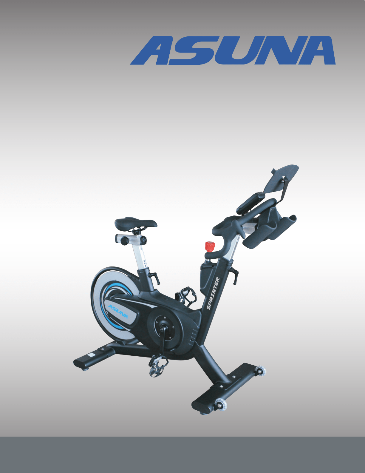
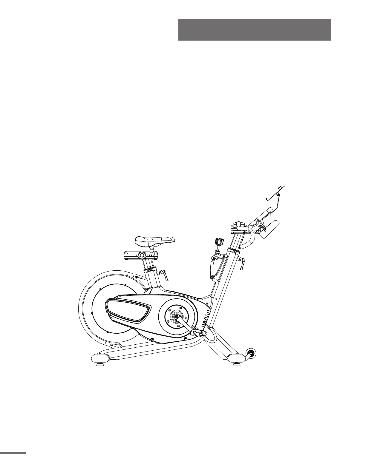
ASUNA 6100
SPRINTING COMMERCIAL
INDOOR CYCLING BIKE
Owner's Manual
Made in China

ATTENTION: Please verify that all parts associated with this product are in good condition and
accounted for. During the assembly process please be sure to follow each step accordingly as
it has been explained within the manual.
WARNING: During assembly, it is recommended that all bolts be tightened by hand. Upon
completing assembly, bolts should then be properly secured using the wrench provided. To
avoid injury, check bolts carefully before use.
IMPORTANT! Please retain owner’s manual for maintenance and adjustment
instructions. Your satisfaction is very important to us, PLEASE DO NOT RETURN UNTIL
YOU HAVE CONTACTED US:
[email protected] or 1- 877 - 90SUNNY
(877-907-8669).
INDEX
IMPORTANT SAFETY INFORMATION ..................................................................................1
EXPLODED DRAWING ......................................................................................................... 2
PARTS LIST ....................................................................................................................... 3-4
ASSEMBLY PARTS LIST / TOOLS & HARDWARE ............................................................ 5
ASSEMBLY INSTRUCTIONS ...........................................................................................6-10
USER INSTRUCTIONS ...................................................................................................11-14
MAINTENANCE ..............................................................................................................15-17
SPD PEDAL INSTALLATION ..............................................................................................18
METER INSTRUCTION ....................................................................................................19-21
CHEST BELT INSTRUCTION .............................................................................................. 22
PRODUCT SPECIFICATIONS ............................................................................................. 23

IMPORTANT SAFETY INFORMATION
We thank you for choosing our product. To ensure your safety and health, please use this
equipment correctly. It is important to read this entire manual before assembling and using
the equipment. Safe and effective use can only be achieved if the equipment is assembled,
maintained and used properly. It is your responsibility to ensure that all users of the
equipment are informed of all warnings and precautions.
1. Before starting any exercise program you should consult your physician to determine if
you have any medical or physical conditions that could put your health and safety at risk,
or prevent you from using the equipment properly. Your physician’s advice is essential if
you are taking medication that affects your heart rate, blood pressure or cholesterol level.
2. Be aware of your body’s signals. Incorrect or excessive exercise can damage your
health. Stop exercising if you experience any of the following symptoms: pain, tightness
in your chest, irregular heartbeat, shortness of breath, lightheadedness, dizziness or
feelings of nausea. If you do experience any of these conditions, you should consult your
physician before continuing with your exercise program.
3. Keep children and pets away from the equipment. The equipment is designed for adult
use only.
4. Use the equipment on a solid, flat level surface with a protective cover for your floor or
carpet. To ensure safety, the equipment should have at least 4 feet (1.2 M) of free space
all around it.
5. Ensure that all nuts and bolts are securely tightened before using the equipment. The
safety of the equipment can only be maintained if it is regularly examined for damage
and/or wear and tear.
6. Always use the equipment as indicated. If you find any defective components while
assembling or checking the equipment, or if you hear any unusual noises coming from
the equipment during exercise, discontinue use of the equipment immediately and do not
use until the problem has been rectified.
7. Wear suitable clothing while using the equipment. Avoid wearing loose clothing that may
become entangled in the equipment.
8. Do not place fingers or objects into the moving parts of the equipment
9. The maximum weight capacity of this unit is 350 pounds (160 kg).
10.The equipment is not suitable for therapeutic use.
11.To avoid bodily injury and/ or damage to the product or property, proper lifting and
moving is required.
12.Your product is intended for use in cool, dry conditions. You should avoid storage in
extreme cold, hot or damp areas as this may lead to corrosion and other related
problems.
13.This equipment is designed for indoor and home use only! It is not intended for
commercial use!
1
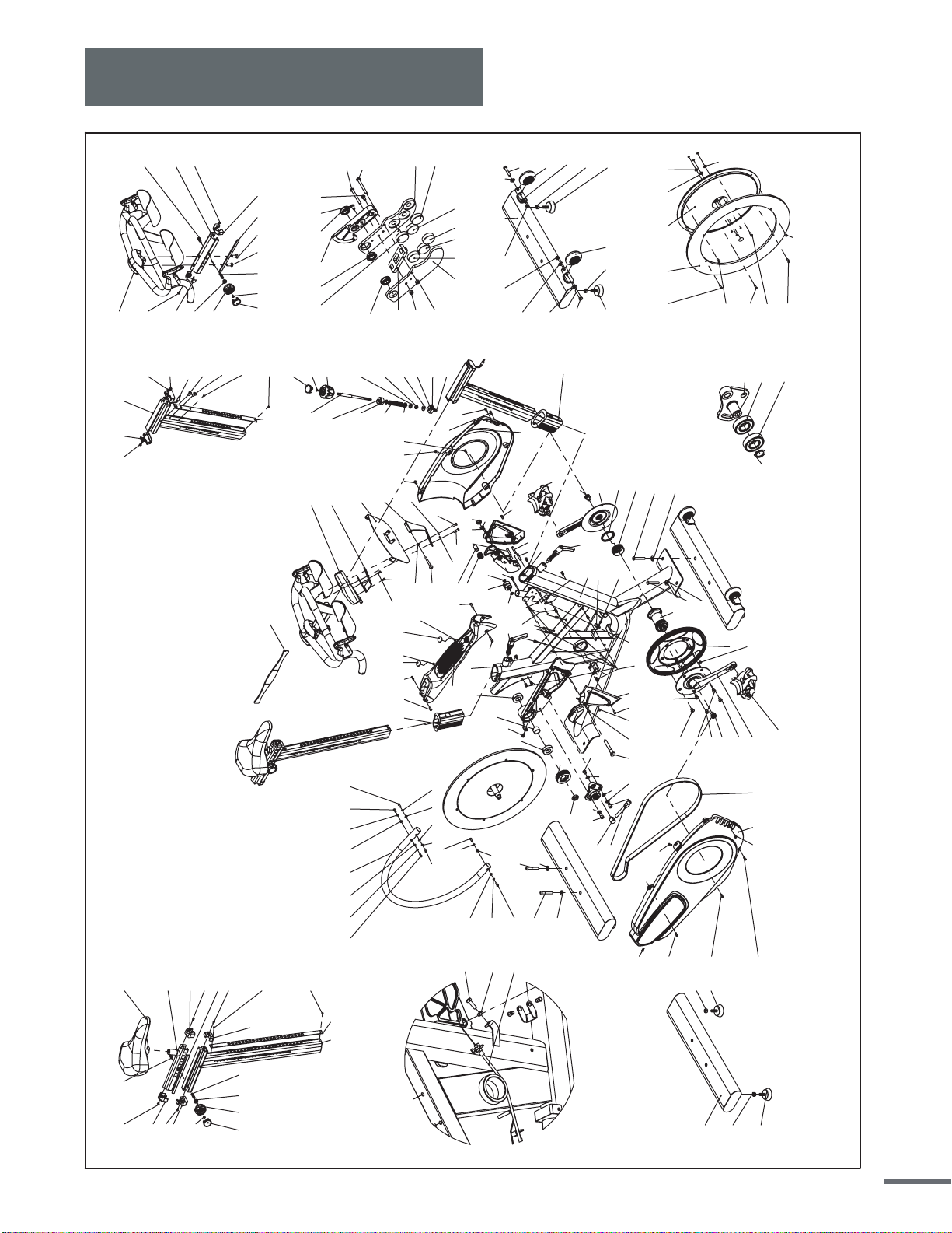
Exploded Drawing
2
2
9
8
6
36R
7
3
4
5
11
9
36L
63
34
44 20
50 4821
16
14
12
15
12
2
38
43
45
27
26
25
24
28
29
41
42
30
31
40
32
33
35
53
37
43
505453
13
54
53
50
49
23
22
56
34
17
18
55
19
1
52
50
46
10
61
2
2
34
41
50
50
50 54 53
50
50
54
53
66
65
68
67
120
123
121
83
126
119
38
8
125
60
38
40
40
39
39
39
50
50
50
50 50
50 50 50
50
50
62
62
5353 5454
50
63
63
34
5050
474750
50
51
51
55
60
61
63
34
123
8
8
8
8
83 86
87
84
85
88
83
82
124
87
82
93
94
83
90
9195
92
89
77
127
78
79128
83
95
116
34
105
117
106
118
34
105
118
106
34
34
64 64
117
106
105
104
105
106
109
108
107
111
111
111
109
109
109
109
109
103 97 83
101
99
98
96
102
100
83
101
97
97
102
96
96
96 96 96
113
115 114
114
80
81
69
71
74
76
7270
75
73
83
77 78 127
79
128
82
82
83
83
83
57
58
59
122
6100
50
2

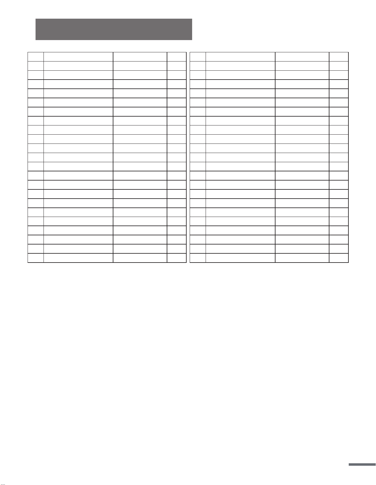
Parts List
Description
Tablet Holder Assembly
Tablet Holder
Flat Washer
Flat Cross Hex Screw
Seat Slider
Seat Post Assembly
Seat Slider Rail
Seat Post Panel
Top Cover(Back)
Top Cover(Front)
Bottom Cover(Back)
Bottom Cover(Front)
Adjustment Knob
Knob Plug Pin
Flat Cross Head Screw
Saddle
Handle Pop-Pin(Short)
Flat Cross Head Screw
Flat Cross Head Screw
Handlebar Post Assembly
Bottom Cover(Front)
Bottom Cover(Back)
Hex-Socket Flat Hex Screw
Handrail Panel
Handlebar and Water Bottle Holder Assembly
Adjust Handlebar Block(Top)
Top Cover(Front)
Top Cover(Back)
Handle Pop-Pin
Adjust Handlebar Block
Flat Inner Hex Screw
Permanent Magnet
Bearing Lf-1910zz
Brake Block-Right
Brake Block-Left
Brake Gasket Assembly
Flat Cross Head Screw
Nylon Nut
Brake Line Turntable
Rear Stabilizer
Hex Nut
Leveler Foot
Qty
1
1
1
1
1
1
1
1
1
1
1
1
2
2
2
1
1
4
11
1
1
1
2
1
1
1
1
1
1
1
2
6
3
1
1
1
2
2
1
1
4
4
No.
65
66
67
68
69
70
71
72
73
74
75
76
77
78
79
80
81
82
83
84
85
86
87
88
89
90
91
92
93
94
95
96
97
98
99
100
101
102
103
104
105
106
Qty
1
16
1
1
1
1
1
6
2
1
1
2
1
1
1
1
1
1
1
1
1
1
1
1
1
1
1
1
1
1
1
1
1
9
1
1
1
3
3
3
2
1
No.
1
2
3
4
5
6
7
8
9
10
11
12
13
14
15
16
17
18
19
20
21
22
23
24
25
26
27
28
29
30
31
32
33
34
35
36L/R
37
38
39
40
41
42
Description
Frame Assembly
Hex Blind Nut
Bottom Bracket Set
Left Cup Of Bottom Bracket
Bottom Bracket Left Fixed Circle
Right Crank
Sprocket / Pulley
Hex-Socket Flat Hex Screw
Crank Fixed Screw
Permanent Magnet
Left Crank
Bearing
Outer Circle Tube Assembly
Front Sprocket/ Pulley
Hub Lining
Hex Nut
Idler Pulley Adjust Screw
Idler Pulley Positioning Nut
Idler Pulley Arm Bushing
Belt
Brake Block Axle
Brake Block Axle Lining
Brake Spring
Brake Lever
Brake Knob
Flat Cross Head Screw
Brake Knob Cover
Brake Cover
Flat Washer
Compression Spring
Square Plastic Bushing
Washer
Nylon Nut
Flat Washer
Slider Block
Pedal
Nylon Nut
Flat Washer
Hand Brake Rotating Shaft Pin
E Type Circlip
Handlebar Adjustment Knob
Crown Block
Spec.
Sus304 m6(d12*d6.5*2.0t)
Sus304 (m6*p1.0*55l)
(UCP)M4*P0.7*10L
Sus304 (m3*p0.5*6l)
Sus304 (m4*p0.7*8l)
Sus304 (m8*p1.25*12l)
Sus304 (m8*p1.25*25l)
Lf-1910zz
Sus304 (m4*p0.7*40l)
m8*p1.25
Sus304 (φ3/8"*16t*8t)
Spec.
(m8x p1.25x 10l)
6004-2rs
m16*p1.5 Left Tooth*7.8t
Sus304 (d10x218l)
(m4x p0.7x10l)
Sus304 M8(d16*d8.1*1.6t)
(d12*40l*1.5t)
Sus304 (m8*p2.0)
Sus304 m8(d19*d8.5*1.0t)
Vp-S2
(m5*p0.8)
M8(d16*d8.2*1.0t)
3
Ordering Replacement Parts (U.S. and Canadian Customers only)
Please provide the following information in order for us to accurately identify the part(s) needed:
√ The model number (found on cover of manual)
√ The product name (found on cover of manual)
√ The part number found on the “EXPLODED DIAGRAM” and “PARTS LIST” (found near the
front of the manual)
No.
43
44
45
46
47
48
49
50
51
52
53
54
55
56
57
58
59
60
61
62
63
64
Description
Bushing
Right Guard
Left Guard
Guard( Top)
Guard( Top) Cover
Right Brake Cover
Left Brake Cover
Hex-Socket Flat Head
Hex-Socket Flat Head
Round Head Cross Tapping Screw
Flat Washer
Spring Washer
Flat Cross Hex Screw
Nylon Nut
Outer Hex Screw
Hex Nut (Ucp)
Brake Line
Nylon Bushing
Galvanized Iron Screw
Flat Washer
Flat Cross Hex Screw
Nylon Nut
Qty
2
1
1
1
2
1
1
24
2
1
7
6
2
1
1
1
1
2
2
2
4
2
No.
107
108
109
110
111
112
113
114
115
116
117
118
119
120
121
122
123
124
125
126
127
128
Description
Flywheel
Aluminum Ring (Flywheel)
Hex-Socket Flat Hex Screw
Flywheel Axis
Spring Washer
Hex-Socket Flat Hex Screw
Idler Pulley Arm
Bearing
C Type Retaining Ring
Front Stabilizer
Transport Wheel
Hex Screw
Flat Washer
Fixing Stator For Meter
Meter
Heart Rate Strap
Round Head Cross Screw
Meter Connection Wire A
Meter Connection Wire B
Plastic Fixed Block
Screw (UCP)
Knob Cover
Qty
1
1
6
1
3
3
1
2
1
1
2
2
1
1
1
1
2
1
1
1
2
2
Parts List
Spec.
(m5*p0.8*14l)
(m5*p0.8*25l)
m5(φ5.5*φ13*1.0t)
(m8*p1.25*15l)
(m10*p1.5)
(m8xp1.25x45l)
(Ucp)m6*p1.0*5.0t
Sus304 m6(d16*d6.5*1.0t)
Sus 304 M8*P1.25*55L
(m8*p1.25)
Spec.
Sus304 (m5*p0.8*16l)
s45c(Ucp)d20*95l+d60*14l
Sus304 (m8*p1.25*45l)
Sus304 m10(d16*d10.2*1.0t)
Screw m5*10
φ9*27.5L
4
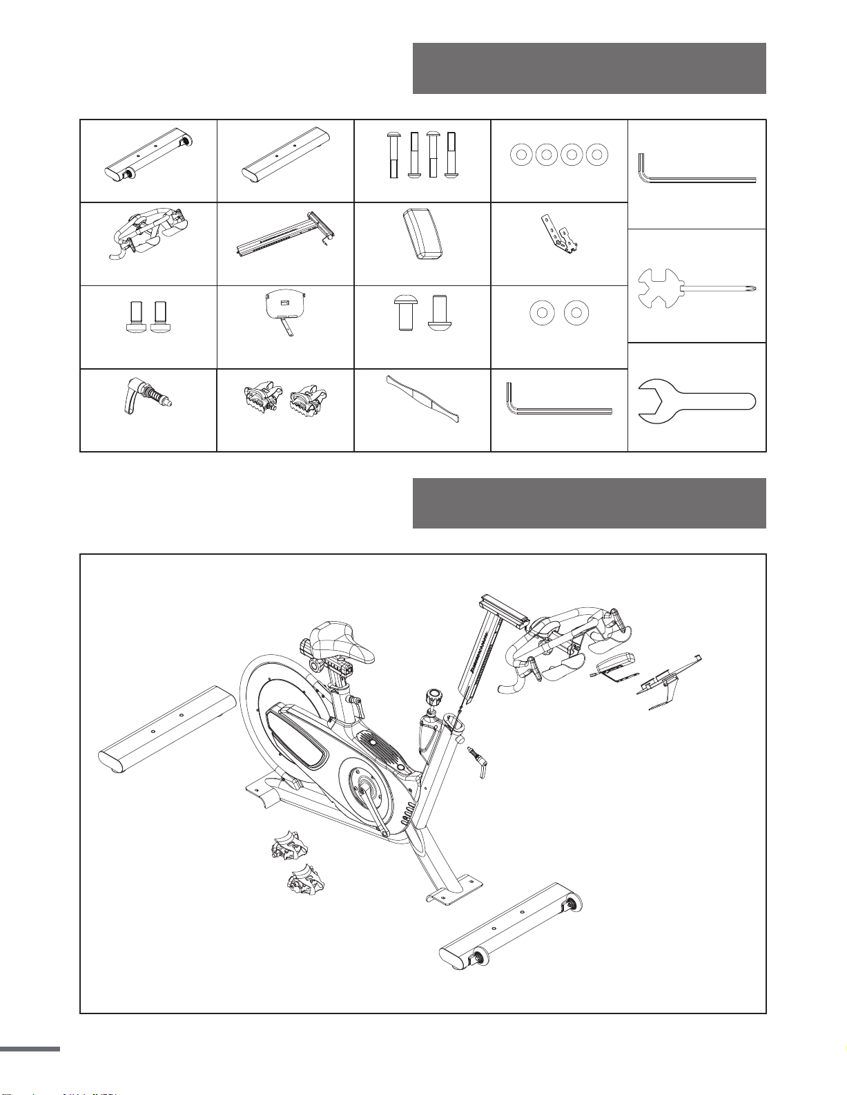
Tools & Hardware
Assembly Parts List
#63
Hex-Socket Screw (4PCS)
#34
Flat Washer (4PCS)
#89
Handlebar and Water Bole Holder Assembly
(1PCS)
#120
Fixing Stator For Meter (1PCS)
#121
Meter (1PCS)
#61
HexSocket Screw (2PCS)
#62
Flat Washer (2PCS)
#66
Tablet Holder (1PCS)
#122
Heart Rate Strap (1PCS)
#36
Pedal Vp-S2 (L/R 2PCS)
A
#123
Round Head Cross Screw (2PCS)
#41
Handlebar Adjustment Knob
(1PCS)
#104
Rear Stabilizer
(1PCS)
#116
Front Stabilizer
(1PCS)
B
D
Combinaon Cross Wrench
13/14/15/mm
C
#84
Handlebar Post Assembly(1PCS)
L-Hex Wrench
4mm/60Lx25L
Open end wrench
22mm
L-Hex Wrench
5mm/76Lx27L
5
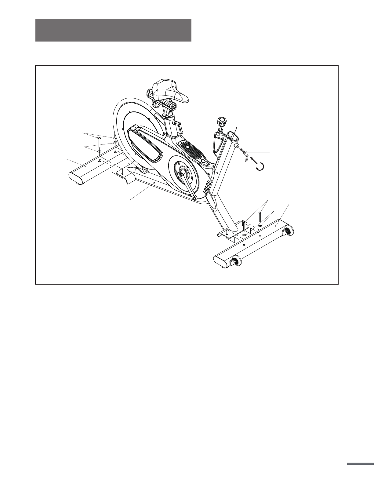
Assembly Instructions
STEP 1:
104
63
34
1
63
34
116
41
Attach the Front and Rear Stabilizers (No. 104 and No. 116) to the Main Frame (No. 1) using
4 Hex Screws (No. 63), 4 Flat Washers (No. 34). Tighten and secure using Hex Wrench (B).
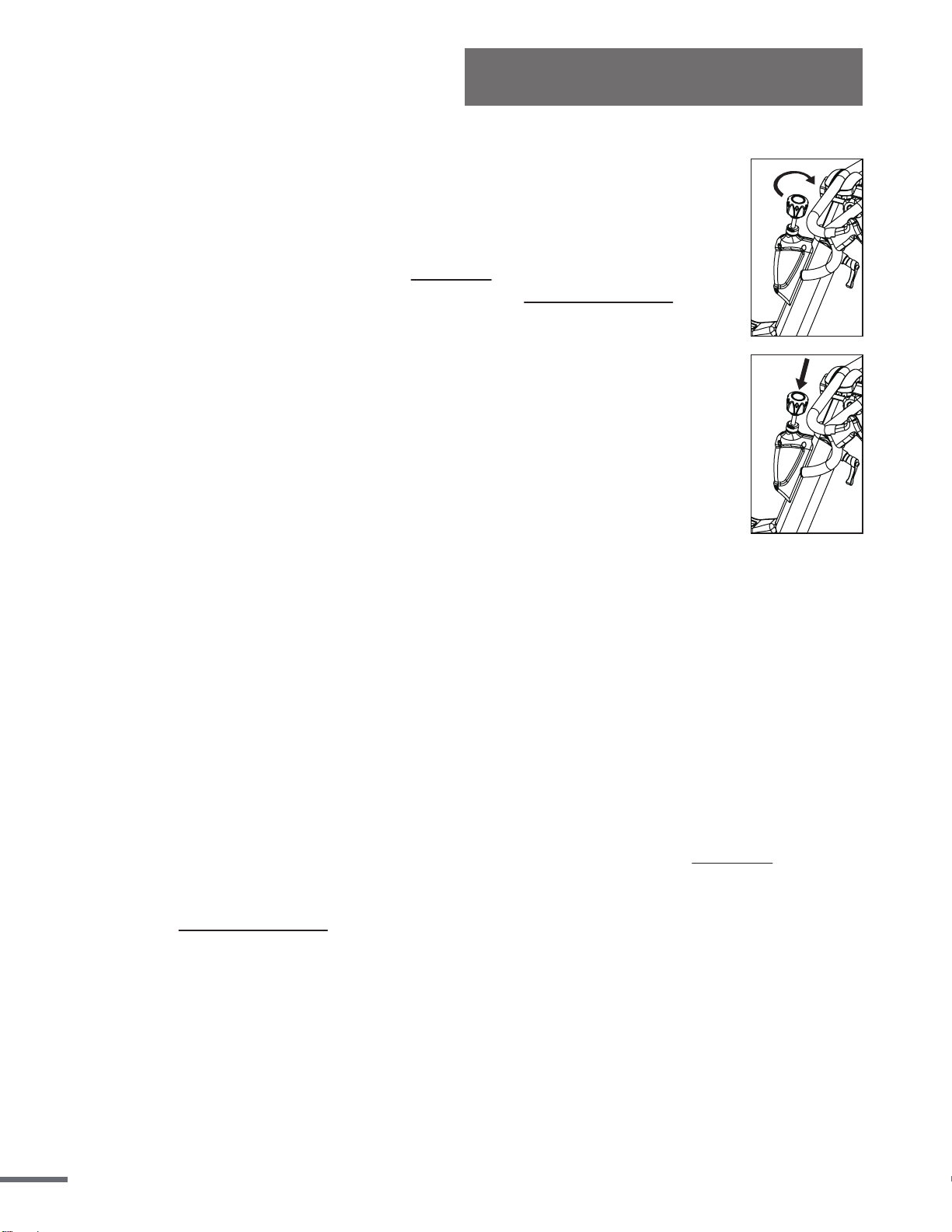
Handlebar Adjustment Knob Assembly
Remove the Handlebar Adjustment Knob (No. 41) from the Pedal bag and turn clockwise to
tighten firmly into the frame with Wrench (D).
6
Assembly Instructions
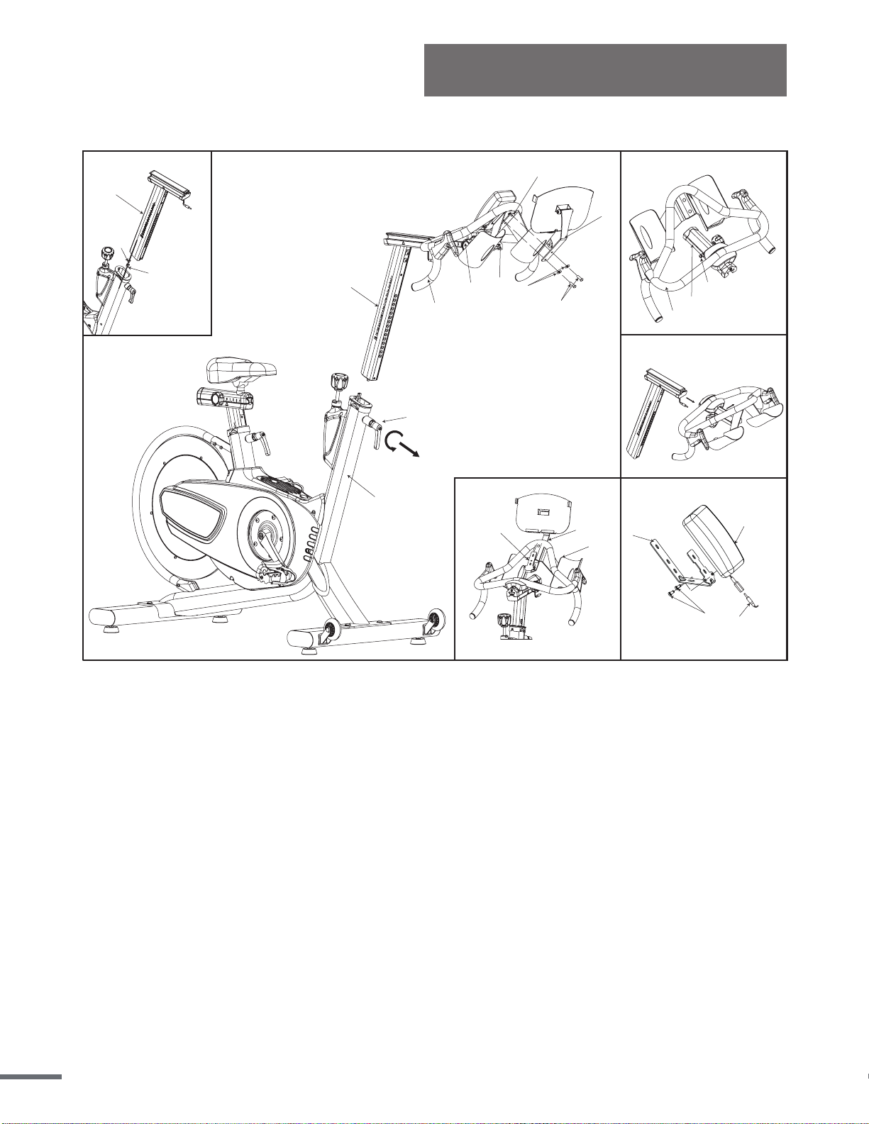
STEP 2:
Please connect the Meter Connection Wire A (No. 124) and Meter Connection Wire B (No.
125) when you insert the Handlebar Post (No. 84). Insert the Handlebar Post (No. 84) into
the front tube of the Main Frame (No. 1). Use the Handlebar Adjustment Knob (No. 41) to
adjust the handlebar to the desired height and secure the handlebar in position.
Install the Handlebar (No. 89) into the Handlebar Post (No. 84). Pull out Handle Pop-Pin
(No. 93) and slide the handlebar onto the Adjust Handlebar Block (top) (No. 90).
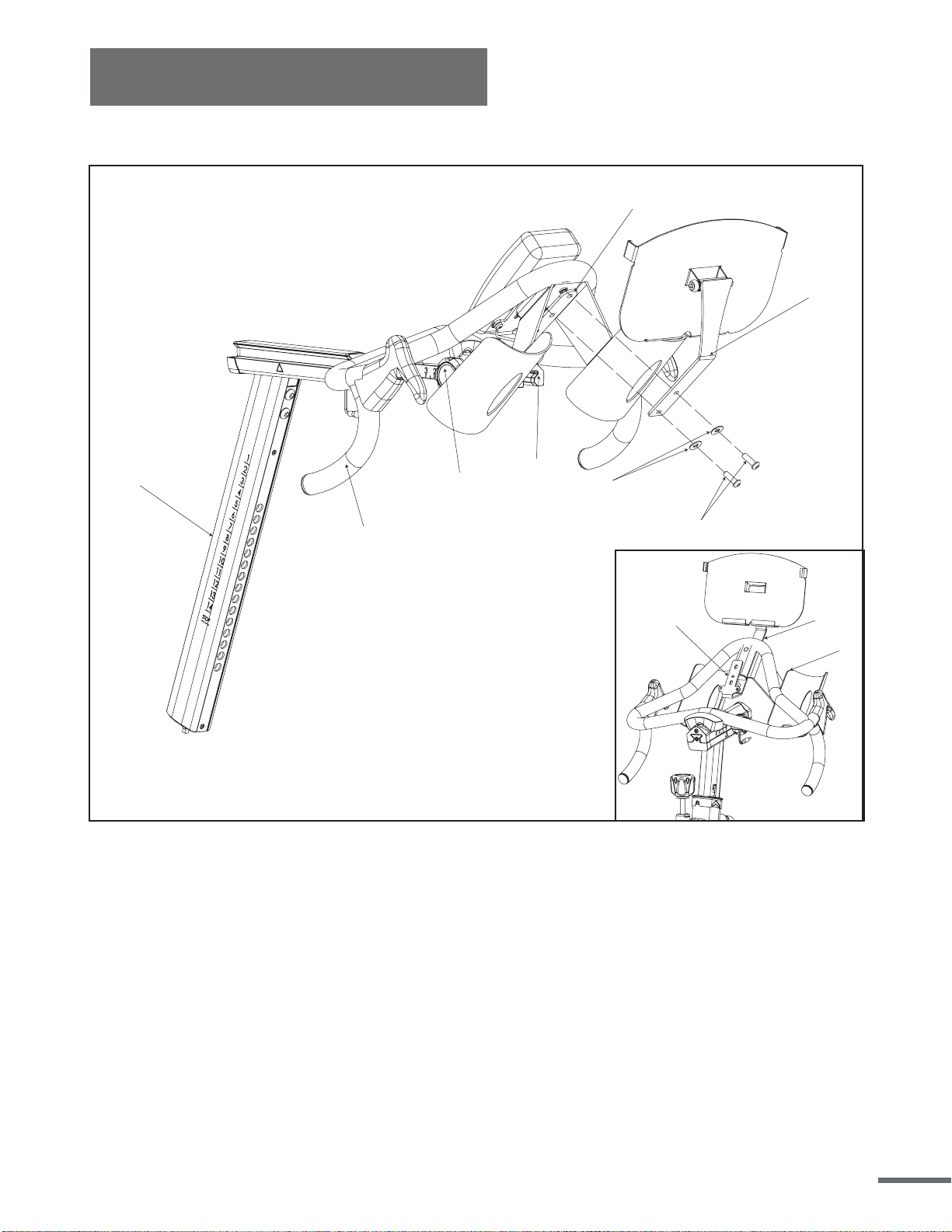
METER AND TABLET HOLDER ASSEMBLY INSTRUCTION
Install 2 pieces of 1.5V #AAA batteries included. Remove the 2 Cross Screws (No. 123)
from the back of the Meter (No. 121). Place the Stator (No. 120) on the back of the meter and
secure using the 2 Cross Screws (No. 123) you just removed. Tighten with Combination
Cross Wrench (C).
Position the Stator (No. 120) on the Handlebar (No. 89), making sure to align the screw holes
with the screw holes of the Handlebar (No. 89). Align the screw holes of the Tablet Holder
(No. 66) with the Stator (No. 120) and the Handlebar (No. 89). Secure using 2 Screws (No.
61) and 2 Flat Washers (No. 62) and tighten with L-hex Wrench (A).
Connect Meter Connection Wire A (No. 124) with the Meter (No. 121).
3
123
120
121
124
1
125
124
2a
84
66
1
89
62
61
41
77
120
90
4
66
89
120
7
2
93
89
90
84
66
89
120
89
84
66
62
61
77
120
90
ALTERNATE VIEW FOR METER AND TABLET HOLDER ASSEMBLY
Assembly Instructions
8
Assembly Instructions
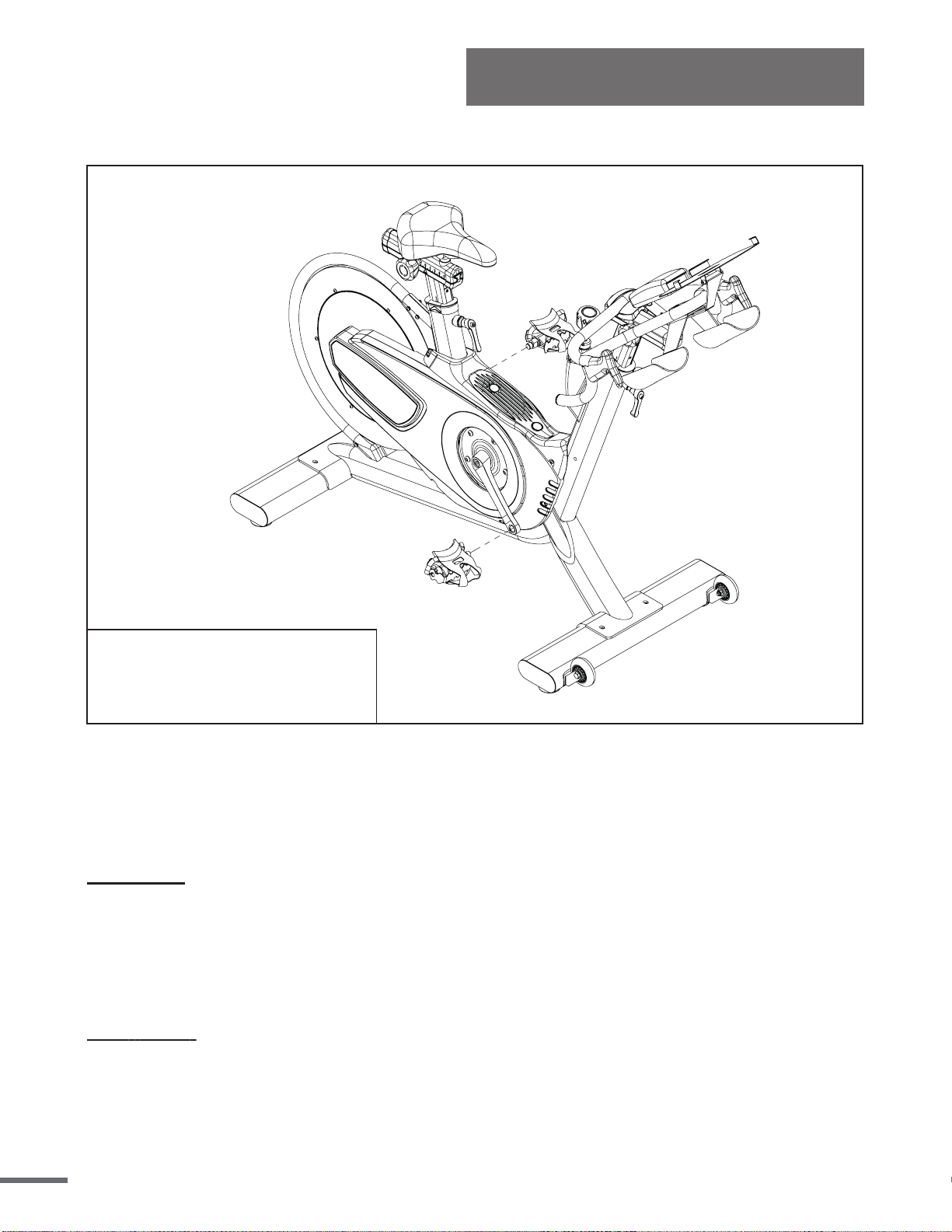
STEP 3:
IMPORTANT:Please read these
instructions carefully. Failure to do
so may cause permanent damage to
your bike.
Connect Pedals L/R (No. 36) onto the Left and Right Crank Arms (No. 6 and No. 11). Before
you begin, immobilize the crank arms by turning the Knob (No. 25) all the way to the right.
NOTE: Pedals L/R (No. 36) are marked L for the Left pedal and R for the Right pedal.
Left Pedal: Align the left pedal, Pedal L (No. 36) with the Left Crank Arm (No. 11) at 90
degrees. Gently insert the pedal into the crank arm, turn the pedal counterclockwise as tightly
as you can with your hand. Tighten and secure with Combination Wrench (C).
IMPORTANT: The Left Pedal (No. 36) contains reverse threading. When installing, you must
turn it counterclockwise to tighten.
Right Pedal: Align the right pedal, Pedal R (No. 36) with the Right Crank Arm (No. 6) at 90
degrees. Gently insert the pedal into the crank arm, turn the pedal clockwise as tightly as you
can with your hand. Tighten and secure with Combination Wrench (C).
9
Assembly Instructions
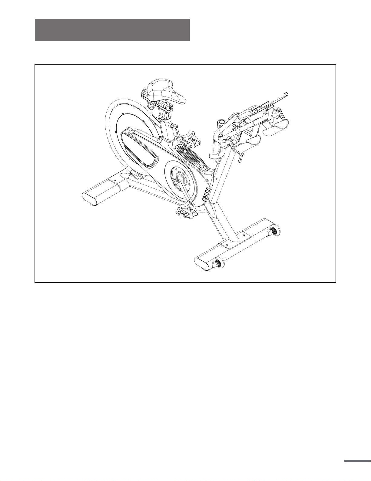
STEP 4:
The assembly is complete!
Before beginning use of the equipment, please be sure to inspect the entire bike
carefully. Ensure that all moving and stationary parts have been properly installed and are
operational; inspect all screws, nuts, and bolts to make sure that they are tightened and
secure.
10

User Instructions
This section will instruct you on how to properly use and make adjustments to components on
the bike. Items which will be covered include seat adjustment, handlebar adjustment,
resistance adjustment, using the emergency brake, pedal strap adjustment, dismounting the
bike, moving the bike, and leveling the bike.
NOTE: Properly assembling the equipment before use is very important, please be sure to
follow all instructions as detailed in the assembly instructions section of the owner’s manual.
SEAT ADJUSTMENT
Proper seat heig
ht helps to ensure the maximum exercise efficiency and comfort while
reducing the risk of injury. Adjusting the seat forward and backwards allows the rider to target
and work lower body muscle groups.
SEAT HEIGHT ADJUSTMENT
Do NOT raise the seat height above the STOP mark on the seat post.
1. To adjust the seat height, turn the Seat Height Adjustment Knob (No. 41) counter-clockwise
and pull it outward to release it. Raise or lower the seat post to the desired height, release the
Seat Height Adjustment Knob gently until it engages a preset hole along the seat post. Turn the
Seat Height Adjustment Knob (No. 41) clockwise to tighten and secure it into place.
2. Rotate the crank so that the pedals are at the 12 and 6 o'clock position.
3. Place your foot into the toe cage of the pedal closest to the floor and mount the bike, ensure
that the ball of your foot is over the center of the pedal. If your leg is too straight or your foot
cannot touch the pedal you will need to lower the seat. If your leg is bent too much you will need
to raise the seat.
4. If necessary, you may need to make several different seat height adjustments in orderto find
the most comfortable position. Repeat the instructions of Steps 1, 2 & 3 until you locate the
desired seat position.
5. When you have obtained the desired seat position, be sure to note the number on the seat post
for future reference.
11

User Instructions
SEAT SLIDER ADJUSTMENT
1. Simply loosen the Adjustment Knob (No. 77) counter-clockwise and slide the Seat (No. 80)
forward or backwards to the desired position.
2. Once the seat has been set in the desired position, turn the Adjustment Knob (No. 77)
clockwise to tighten and secure the Seat (No. 80) in place.
NOTE: If necessary, you may need to make several different adjustments to the seat in
order to find the most comfortable position. Repeat the instructions of Step 1 & 2 until you
locate the desired seat position.
HANDLEBAR ADJUSTMENT
Proper handlebar height helps to ensure the maximum exercise efficiency and comfort.
Handlebar height is a matter of performance, adjusting the handlebars to a higher level will give
the rider more of an upright position, lowering them will result in a more prone position. If
discomfort in the back occurs during exercise the handlebars should be more accurately
adjusted to your personal requirements.
HANDLEBAR HEIGHT ADJUSTMENT
Do NOT raise the handlebar height above the STOP mark on the handlebar post.
1. Begin by positioning the handlebars at the same height as the seat. Mount the bike and
assume a riding position. Use this position to obtain a feel for the proper location of the
handlebar that suits your comfort.
2. Turn Handlebar Adjustment Knob (No. 41) counter-clockwise and pull it outward to release
it. Raise or lower the Handlebar Post (No. 84) to the desired height, release the Handlebar
Adjustment Knob gently until it engages a preset hole along the handlebar post. Turn the
Handlebar Adjustment Knob (No. 41) clockwise to tighten and secure it into place.
Note: If necessary, you may need to make several different handlebar height adjustments in
order to find the most comfortable position. Repeat the instructions of Steps 1 & 2 until you
locate the desired handlebar position.
When you have obtained the desired handlebar position, be sure to note the number on the
handlebar post for future reference.
12
User Instructions
RESISTANCE ADJUSTMENT
In order to change the intensity of your workout, the resistance can be easily
adjusted at any time while riding.
Turn the Resistance Knob (No. 25) clockwise (+) to increase the level of
resistance. Turn the Resistance Knob (No. 25) counter-clockwise (-) to
decrease the level of resistance.
EMERGENCY BRAKE
In case of emergency and before dismounting the bike, press directly down on
the Resistance Knob (No. 25) to enforce the brake system and bring the
flywheel to an immediate stop.
PEDAL STRAP ADJUSTMENT
Feet should be securely positioned in the toe clips during exercise. Place your feet as far
forward into the toe-clips as you can. With your feet in place, turn the crank to bring one foot to
within arm’s reach, grasp the pedal strap and pull it upward to tighten the toe-clip cage
, then
insert the strap back into the hoop of the toe-clip. Repeat this process to secure your other foot.
LEVELING THE BIKE
In order to achieve a smooth and comfortable exercise during use, you must ensure that the
stability of the bike is correct. If you notice that the bike is unbalanced, you may adjust the
leveling feet located beneath the front and rear stabilizers of the bike. To do so, use the
Combination Wrench (C) to loosen the Hex Nut (No. 105) by turning it clockwise. With the
nut loosened, rotate the Leveler Foot (No. 106) until it is leveled with the surface that the bike
is on. When you have finished adjusting the leveler foot, re-tighten the Hex Nut (No. 105) by
turning it counter-clockwise using the Combination Wrench (C).If required, repeat this
process to adjust the remaining leveler feet on the bike.
13
User Instructions
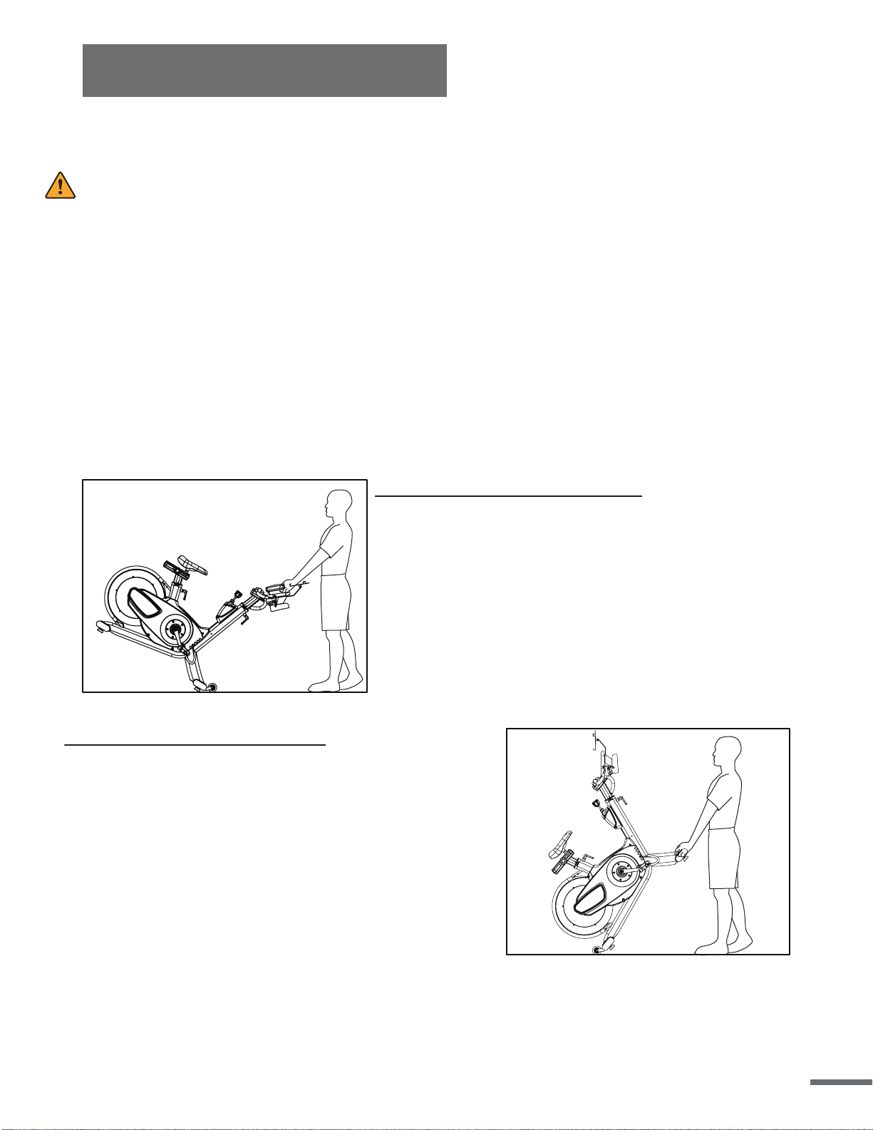
NOTE:When moving the bike, always move with caution as unexpected impacts or
dropping the bike may affect its operation.
A. Wheels on the Front Stabilizer
1.To move the bike, first make sure that the Handlebar
(No. 89) is properly secured.If the handlebar is loose,
tighten the Handlebar Adjustment Knob (No. 41) to
secure it. Next, stand at the front of the bike so that
you’re directly in front of the handlebars. Firmly grasp
and hold each side of the handlebar, place one foot
on the stabilizer and tilt the bike towards you until the
transportation wheels on the front stabilizer touch the
ground. With the wheels securely on the ground,
move the bike to the desired location.
B. Wheels on the Rear Stabilizer
1.Please squat down and grasp the Front Stabilizer (No.
104), one hand on the right and another hand on the
left.
2. Lift up the bike and stand up (the best angles from
stabilizer with ground is 50°.)
3. You can easily roll the bike in any direction.
4. Grasp the Handlebar (No. 89) by your left hand when
you feel the wheels touch the ground.
5. Grasp the Handlebar (No. 89) by your right hand and
put down the bike.
DISMOUNTING THE BIKE
WARNING:
Do NOT attempt to dismount or remove your feet from the pedals until both the flywheel and
the pedals/crank have come to a complete stop. Failure to follow this warning may lead to loss
of control and/or serious injury.
Here are a few examples of how to safely and properly dismount the bike:
1. Reduce the pedal speed until the pedals/crank come to a complete stop.
2. Increase the resistance until the pedals/crank come to a complete stop.
3. Push and hold the resistance knob down to engage the Emergency Brake function, hold
until the pedals/crank come to a complete stop.
MOVING THE BIKE
14
BELT DRIVE TENSION
The belt on this bike was pre-tensioned and pre-lubricated prior to being shipped. The belt
should not require any adjustments upon the bikes initial uses. However, you may need to
make minor tension adjustments over time.
Note:Make sure you adjust the tension equally on both sides when tightening or loosening to
ensure that the flywheel is in alignment with the frame.
Gently move the crank arms back and forth with your hand. If there is more than 1/4”(0.64
cm) of space granted in the movement of the crank before the flywheel starts turning, you will
need to adjust the belt tension.
Maintenance
Note:If you still feel strong vibration even after adjusting the belt, you will need to repeat
these steps again until the issue has been solved.
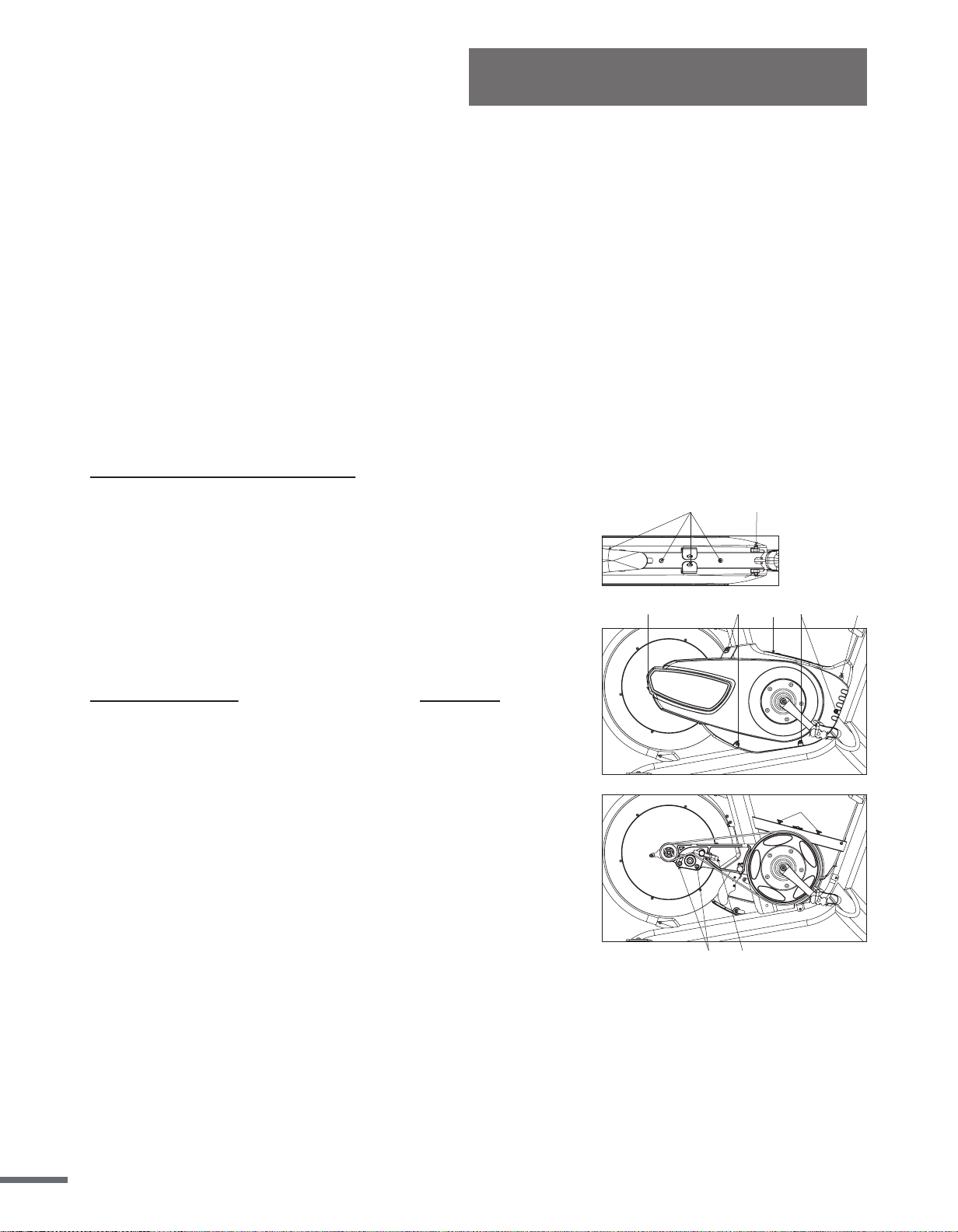
ADJUST THE BELT TENSION:
1. Remove the 2 Guard (Top) Cover (No. 47) on the Guard
(top) (No. 46). Remove the 4 Screws (No. 50) and 2
Screws (No. 51). Remove the Guard (top) (No. 46).
2. Remove the 7 Screws (No. 50) and remove the Right guard
(No. 44).
3. Use L type wrench (B) to loosen 2 Hex Screws (No. 55)
two turns counterclockwise.
4. Use L type wrench (B) to adjust Screw (No. 17). Turn
counter-clockwise to loosen belt. Turn clockwise to tighten
belt. Then adjust the belt. Tighten the 2 Hex Screws (No. 55)
clockwise.
5. Turn the crank to see if belt runs smoothly. You can also try
riding the bike to test the belt tension. If there is still a
problem, repeat step #4 until belt is at correct tension.
6. Put the Right guard (No. 44) back on and re-tighten the
7. Screws (No. 50). Putting the Guard (top) (No. 46) back on
and re-tighten the 4 Screws (No. 50) and 2 Screws (No. 51).
51
1755
50
51
5050
50
46
47
15

Maintenance
Part
Recommended Action
Cleaner
Lubricant
Bike
(Frame,
seat/handlebar
post)
Wipe down to remove any
moisture. This is important
because excessive sweat or
water may lead to rust or
corrosion
Damp cloth or soap & water
diluted non- abrasive
cleaning liquids
N/A
Flywheel Check the alignment N/A
N/A
Pedal/Crank
Arms
Inspect for wear and tear,
excessive play indicates
that the pedal is loose and
needs to be tightened or
that the pedal and/or crank
arm threading may be
worn. Replace if necessary
before continuing use.
N/A
N/A
Main Frame
While riding, check for
vibration. If the bike vibrates
during use you may need to
tighten the pedals, bottom
bracket, or adjust the belt
tension.
N/A
N/A
IMPORTANT:
Safe and effective use of your equipment can only be assured if the equipment is
assembled, maintained, and used properly. Any components found to be worn and/or
damaged should be replaced before continuing use of the equipment. Equipment should
only be used and stored indoors. Prolonged exposure to weathering and changes in
temperature and humidity may have a severe impact on parts of the machine.
Daily Maintenance:
The life span and performance of your bike will be determi
ned by how consistently you
perform the daily maintenance.
16

Maintenance
Lubricant
N/A
N/A
aren’t loose. Check foot pads for wear.
Part
Recommended Action
Cleaner
Toe Clips/
Toe Straps
Inspect for wear and tear. Re-tighten if
loose or disconnected. Replace if needed.
N/A N/A
Hardware
Tighten all the frame hardware (Bolts, nuts,
screws)
N/A N/A
Adj. Knob
Inspect, clean, lubricate, and tighten all
adjustment knobs
Damp cloth WD-40 / 3-n-1
Stabilizers
/Foot Pads
Inspect the stabilizers to ensure that they
N/A
Bottom
Bracket
Visually inspect to ensure that it is tight and
secure. Re-attach and re-tighten if needed.
N/A
Lubricant
Part
Recommended Action
Cleaner
Hardware
(Full
Inspection)
Re-check and secure all hardware such
as water bottle holders, flywheel nuts,
brake caliper lock nuts, brake caliper
tension rod nuts, handlebar screws,
chain guard screws and nuts etc.
N/A
N/A
Brake Tension
Rod
Clean and lubricate the brake tension
rod, inspect for signs of wear such as
missing threads.
Small Brush WD-40 / 3-n-1
Seat
Post/Handleba
r
Post and Seat
Slider Tube
Clean and lubricate the seat post,
handlebar post, and seat slider tube.
During cleaning, inspect each part for
any build up, foreign material or wear at
the insertion points. Replace parts if
needed.
Small Brush
WD-40 / 3-n-1
Weekly Maintenance:
This maintenance is the upkeep of the overall performance. Check for vibration and loose
parts during this inspection.
Monthly Maintenance:
This maintenance should be comprehensive and should involve checking the overall frame
and main assembly components.
17
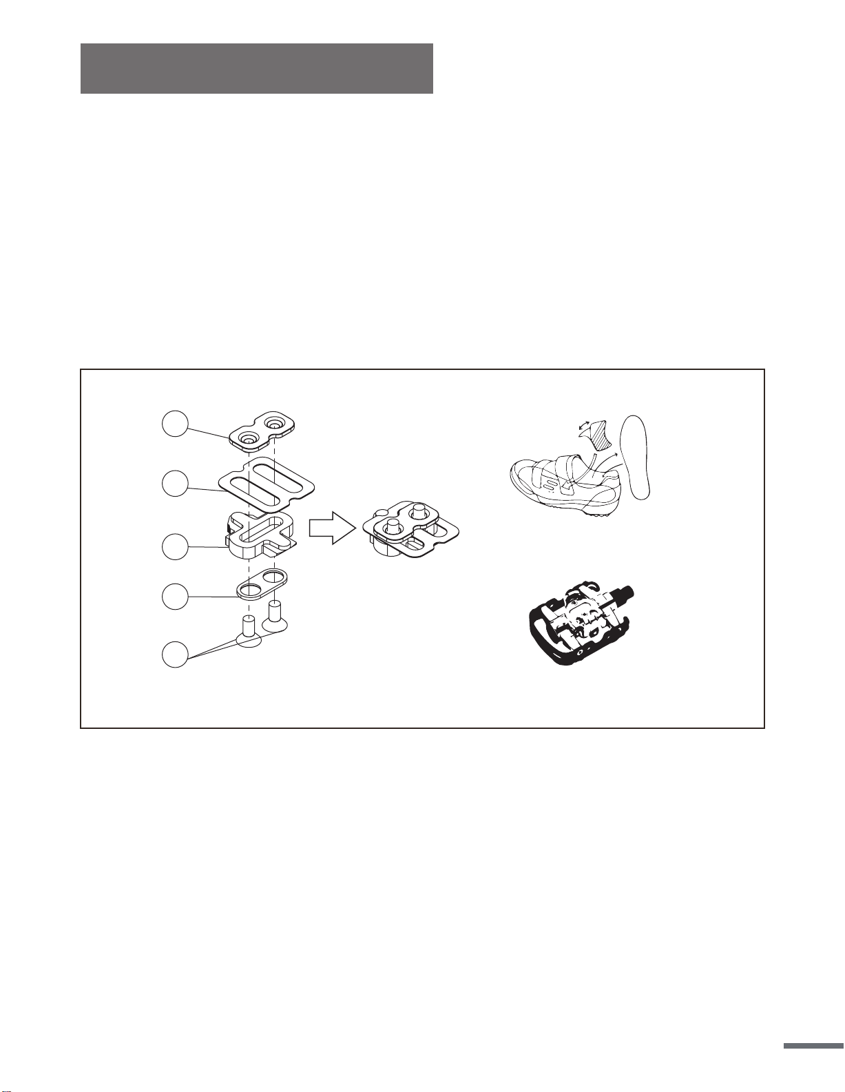
Included with your equipment is a set of SPD cleats compatible to the SPD pedals. Your SPD
pedals have a standard pedal with toe cage on one side, which allows you to use regular
shoes, as well as the SPD side on the other to attach your cleats. In order to use the SPD
pedal, you would have to own a pair of SPD shoes designed to fit the cleats.
Use the image below to see the proper order that the SPD hardware should be placed in. Once
combined, attach the cleats tightly into your shoes with the triangular portion of the cleat
towards the front of the shoe. Ensure the lateral center line of the cleat is aligned to the ball of
your foot and clip into the pedal. Cleat positions can be turned and adjusted. To release the
cleat from the pedal, simply lift and twist your heel.
1
2
3
4
5
SPD cleat set
SPD shoes
SPD pedal
SPD Pedal Installation
18

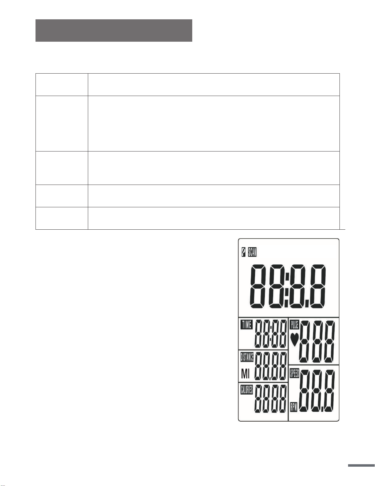
Meter Instruction
DISPLAY FUNCTION:
ITEM DESCRIPTION
SCAN
. In SCAN mode, press MODE/ENTER key to choose funcons.
. Automacally scan through each mode in sequence every 6 seconds.
. The sequence of display when press MODE/ENTER key : TIME→ DIST→CAL→
PULSE→RPM/SPEED
SPEED
. Range 0.0 ~ 99.9
. Without any signal being transmied into the monitor for 4 seconds during
workout, SPEED will display “0.0”
RPM
. Range 0 ~ 999
. Without any signal being transmied into the monitor for 4 seconds during
workout, RPM will display “0”
TIME
. Without seng the target value, me will count up.
. When seng the target value, me will count down from your target me to 0
and alarm will sound or flash.
. Without any signal being transmied into the monitor for 4 seconds during
workout, me will STOP
. Range 0:00 ~ 99:59
DISTANCE
. Without seng the target value, distance will count up.
. When seng the target value, distance will count down from your target
distance to 0 with an alarm sound or flash.
. Range 0.00~99.99
CALORIES
. Without seng the target value, calorie will count up.
. When seng the target value, calories will count down from your target calorie
to 0 with an alarm sound or flash.
. Range 0~9999
PULSE
. Current pulse will display aer 6 seconds when detected by the console.
. Without any pulse signal for 6 seconds, console will display “P”.
. Pulse alarm will sound when current pulse is over the target pulse.
. Range 0-30~230 BPM
19
Meter Instruction
KEY FUNCTION:
ITEM DESCRIPTION
SET
. Press SET key to increase value. Press and hold the key to increase value faster.
. TIME seng range: 00:00~99:00 (Each increment is 1:00)
. CAL seng range: 0~9990 (Each increment is 10)
. DIST seng range: 0.00~99.50 (Each increment is 0.5)
. PULSE seng range: 0-30~230 (Each increment is 1)
MODE/ENTER
. Choose each funcon by pressing MODE/ENTER key.
. Press and hold MODE/ENTER key for 2 seconds to reset all funcons (same feature
as the reset key if press for 2 seconds).
RESET
. In seng mode, press RESET key once to reset the current funcon figures.
. Press RESET key and hold for 2 seconds to reset all funcon figures.
RECOVERY
. Aer the console detects pulse signal, press the RECOVERY key to enter recovery
mode to monitor heart rate recovery ability.
OPERATION PROCEDURE
• LCD will display all segments as Drawing 1.
POWER OFF
• Without any signal being transmitted into the monitor for 4 minutes the monitor will enter
SLEEP mode.
20

Meter Instruction
OPERATION
1. Workout setting
• Press MODE/ENTER key to select the function of TIME, DISTANCE, CALORIES and PULSE.
Use SET Key for setting and press MODE/ENTER key for confirmation.
• For instance the time set-up, when the time value is blinking, you can use SET Key to adjust the
number. Press MODE/ENTER key for confirmation and skip to next set-up. The set-up of DIS-
TANCE, CALORIES and PULSE is the same as TIME set-up.
• Once the workout begins and the console picks up the exercise signal, the value of
SPEED/RPM, TIME, DST and CAL will count up on the display.
Recovery
1. The RECOVERY key will only be valid if pulse is detected.
2. TIME will show "0:60" (seconds) and counts down to 0.
Computer will show F1 to F6 after the countdown to test heart rate recovery status. User can
find the heart rate recovery level based on the chart below.
3.Press RECOVERY key again to return to the beginning.
F1 Outstanding
F2 Excellent
F3 Good
F4 Fair
F5 Below average
F6 Poor
Trouble shooting:
• When the display of LCD is dim, it means the batteries need to be changed.
• If there is no signal when you pedal, please check if the cable is well connected.
NOTE:
1. When stop training for 4 minutes, the main screen will be off.
2. If the computer displays abnormally, please replace the batteries and try again.
21
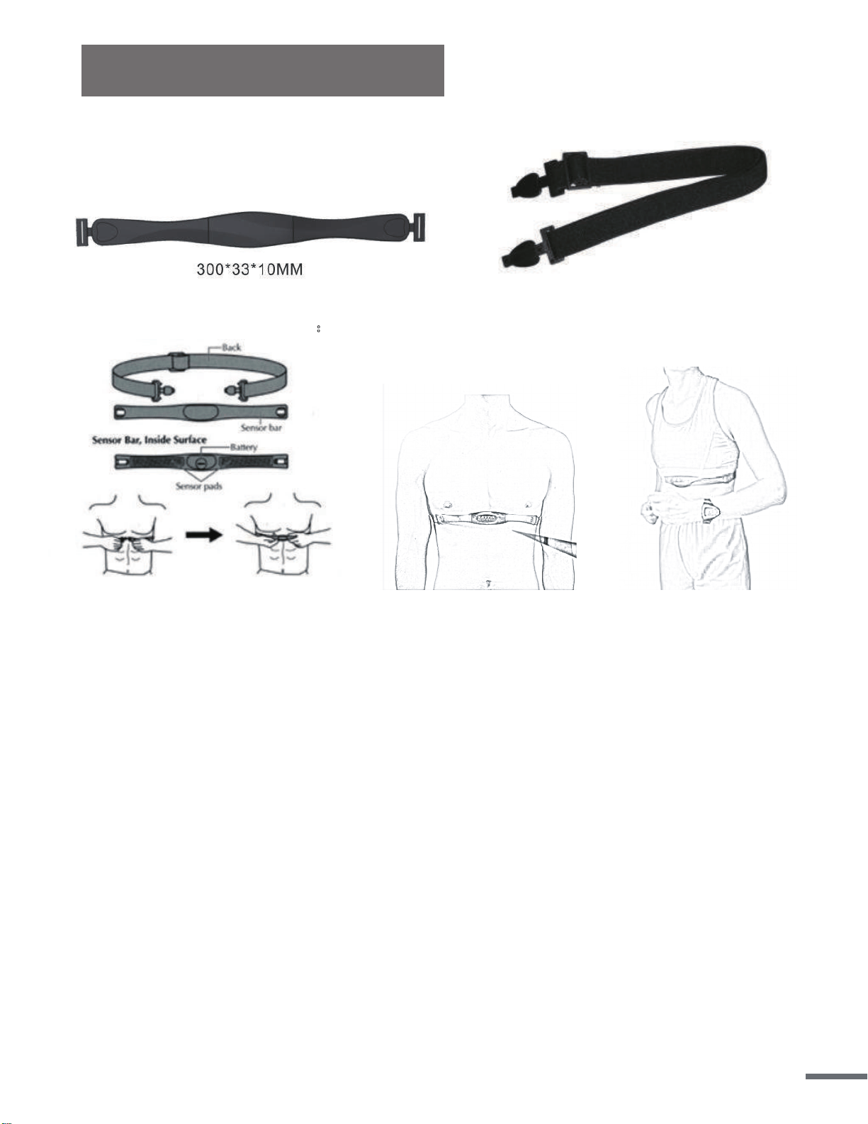
Chest Belt Instruction
I. Product picture:
II. Standard wearing method:
Figure 1 Figure 2 Figure 3
III. Measuring your heart rate:
1. Wet your skin with water before putting on the chest belt, so the belt can detect the signal
better.
2. Put on the chest belt as in Figure 1-3, then the belt can detect your heart rate. After 3 to 5 sec-
onds, the meter will display the PULSE icon and your pulse.
3. If you will not be measuring your heart rate, take off the chest belt.
IV. Note
1. Wear the chest belt in the direction indicated.
2. Make sure the chest belt is as close to your heart as possible.
3. Chest belt transmits data via RF5.3 KHz
4. Signal range of the belt is 35-47 inches (90-120 cm)
5. Battery: The chest belt uses one 3V lithium battery. Factory has installed one in the meter. If
signal range decreases or no signal is detected, replace the battery. The battery is located in
the middle of the -chest belt. Use a coin to turn the cover counterclockwise to open up the
battery compartment.
Dispose of old battery according to your regional guidelines.
6. Waterproof level = 1 ATM
22
Product Specifications
Version 1.3
• Dimensions 59″L x 22″W x 48.4″H
• Assembled Unit Weight 126.7 lbs (57.5 kg)
• Packaged Weight 138.9 lbs (63 kg)
• Maximum User Weight 350 lbs (160 kg)
23