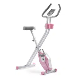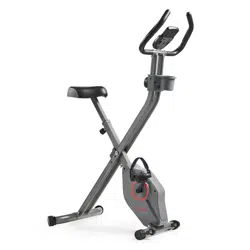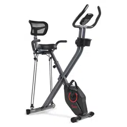
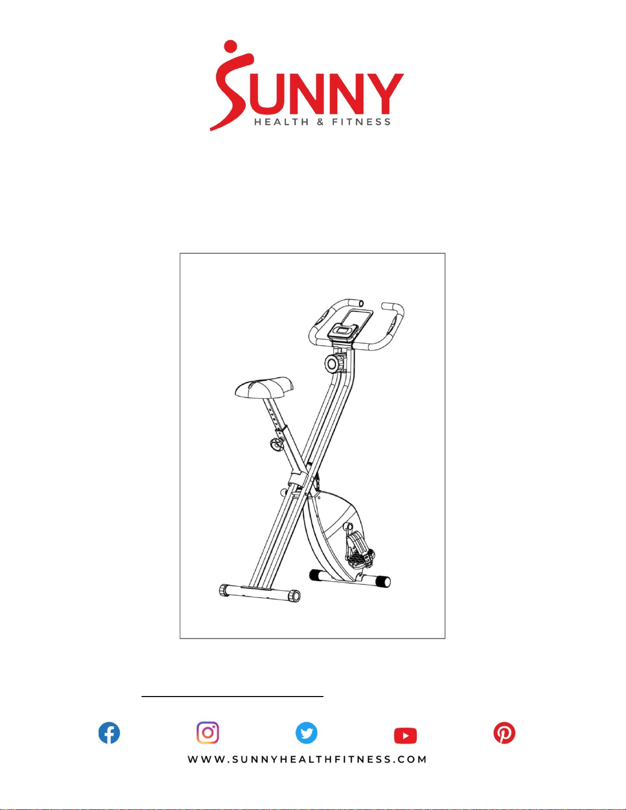
MAGNETIC FOLDABLE EXERCISE BIKE
SF-B2989
USER MANUAL
IMPORTANT! Please retain owner’s manual for maintenance and adjustment instructions.
Your satisfaction is very important to us, PLEASE DO NOT RETURN UNTIL YOU HAVE
CONTACTED US: support@sunnyhealthfitness.com or 1-877-90SUNNY (877-907-8669).

1
IMPORTANT SAFETY INFORMATION
We thank you for choosing our product. To ensure your safety and health, please use this equipment
correctly. It is important to read this entire manual before assembling and using the equipment. Safe
and effective use can only be achieved if the equipment is assembled, maintained and used properly.
It is your responsibility to ensure that all users of the equipment are informed of all warnings and
precautions.
1. Before starting any exercise program, you should consult your physician to determine if you have
any medical or physical conditions that could put your health and safety at risk, or prevent you
from using the equipment properly. Your physician’s advice is essential if you are taking
medication that affects your heart rate, blood pressure or cholesterol level.
2. Be aware of your body’s signals. Incorrect or excessive exercise can damage your health. Stop
exercising if you experience any of the following symptoms: pain, tightness in your chest, irregular
heartbeat, shortness of breath, lightheadedness, dizziness or feelings of nausea. If you do
experience any of these conditions, you should consult your physician before continuing with your
exercise program.
3. Keep children and pets away from the equipment. The equipment is designed for adult use only.
4. Use the equipment on a solid, flat level surface with a protective cover for your floor or carpet. To
ensure safety, the equipment should have at least 2 feet (60 CM) of free space all around it.
5. Ensure that all nuts and bolts are securely tightened before using the equipment. The safety of the
equipment can only be maintained if it is regularly examined for damage and/or wear and tear.
6. Always use the equipment as indicated. If you find any defective components while assembling or
checking the equipment, or if you hear any unusual noises coming from the equipment during
exercise, discontinue use of the equipment immediately and do not use until the problem has
been rectified.
7. Wear suitable clothing while using the equipment. Avoid wearing loose clothing that may become
entangled in the equipment.
8. Do not place fingers or objects into the moving parts of the equipment.
9. The maximum weight capacity of this unit is 220 pounds (100 KG).
10. The equipment is not suitable for therapeutic use.
11. To avoid bodily injury and/or damage to the product or property, proper lifting and moving is
required.
12. Your product is intended for use in cool, dry conditions. You should avoid storage in extreme cold,
hot or damp areas as this may lead to corrosion and other related problems.
13.This equipment is designed for indoor and home use only. It is not intended for commercial use!
2
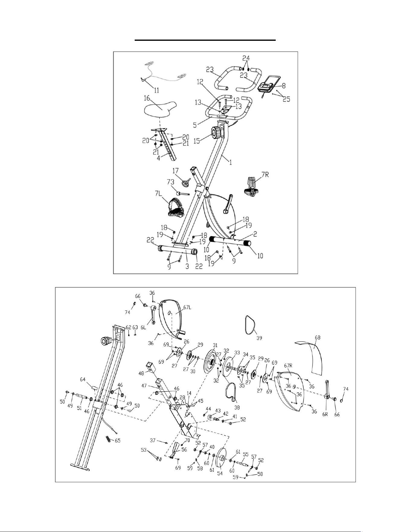
EXPLODED DIAGRAM

3
PARTS LIST
No.
Description
Spec.
Qty
.
No.
Description
Spec.
Qty
.
1 Main Frame 1 35 Screw M6x13 4
2 Front Stabilizer 1 36 Screw ST4x20 7
3 Rear Stabilizer 1 37 Screw M6x12 1
4 Seat Post 1 38 Belt 1
5 Handlebar 1 39 Belt 1
6 L/R Crank 1 pr 40 Hex Nut M10x1.0 4
7 L/R Pedal 1 pr 41 Flat Washer D10x2.0 1
8 Meter 1 42 Idler Wheel Axle 1
9 Carriage Bolt M8x50 4 43 Bearing 1
10 End Cap 2 44 Axle Spring Washer 1
11 Pulse Wire 2 45 Screw M3x10 2
12 Screw M8x38 2 46 Sleeve 6
13 Arc Washer D8x1.5xR11 2 47 Front Bracket 1
14 Sensor Wire 1 48 Square Sleeve 1
15 Tension Controller 1 49 Flat Washer 2
16 Seat 1 50 Screw 2
17 Knob 1 51 Spindle 1
18 Cap Nut M8 4 52 Flange Nut 3
19 Arc Washer D8x1.5xR22 4 53 Magnet 6
20 Flat Washer D8 3 54 Driven Wheel 1
21 Nylon Nut M8 3 55 Driven Wheel Axle 1
22 End cap 2 56 Magnet Board 1
23 Foam Grip 2 57 Adjusting Chain Bolt 2
24 Round Cap 2 58 Adjusting Chain U Mat 2
25 Screw M5x10 2 59 Hex Nut 2
26 Ring Flange 2 60 Flat Washer 2
27 Axle Spring Washer 6 61 Bearing 2
28 Hex Nut M3 2 62 Flat Washer 1
29 Bearing Brake 2 63 Screw 1
30 Wave Washer 1 64 Cushion 1
31 Flywheel 1 65 Spring 1
32 Nylon Nut M6 4 66 Flange Bolt 2
33 Belt Pulley 1 67L/R Belt Cover 1 pr
34 Centre Axle 1 68 Front Cover 1
4
#73 1PC
#25 M5x10 2PCS
No. Description Spec. Qty. No. Description Spec. Qty.
69 Screw M6x10 7 72 Allen Wrench S6 1
70 Plug 1 73 Pull Pin 1
71 Spanner S13, 14, 15 1 74 Crank Cover 2
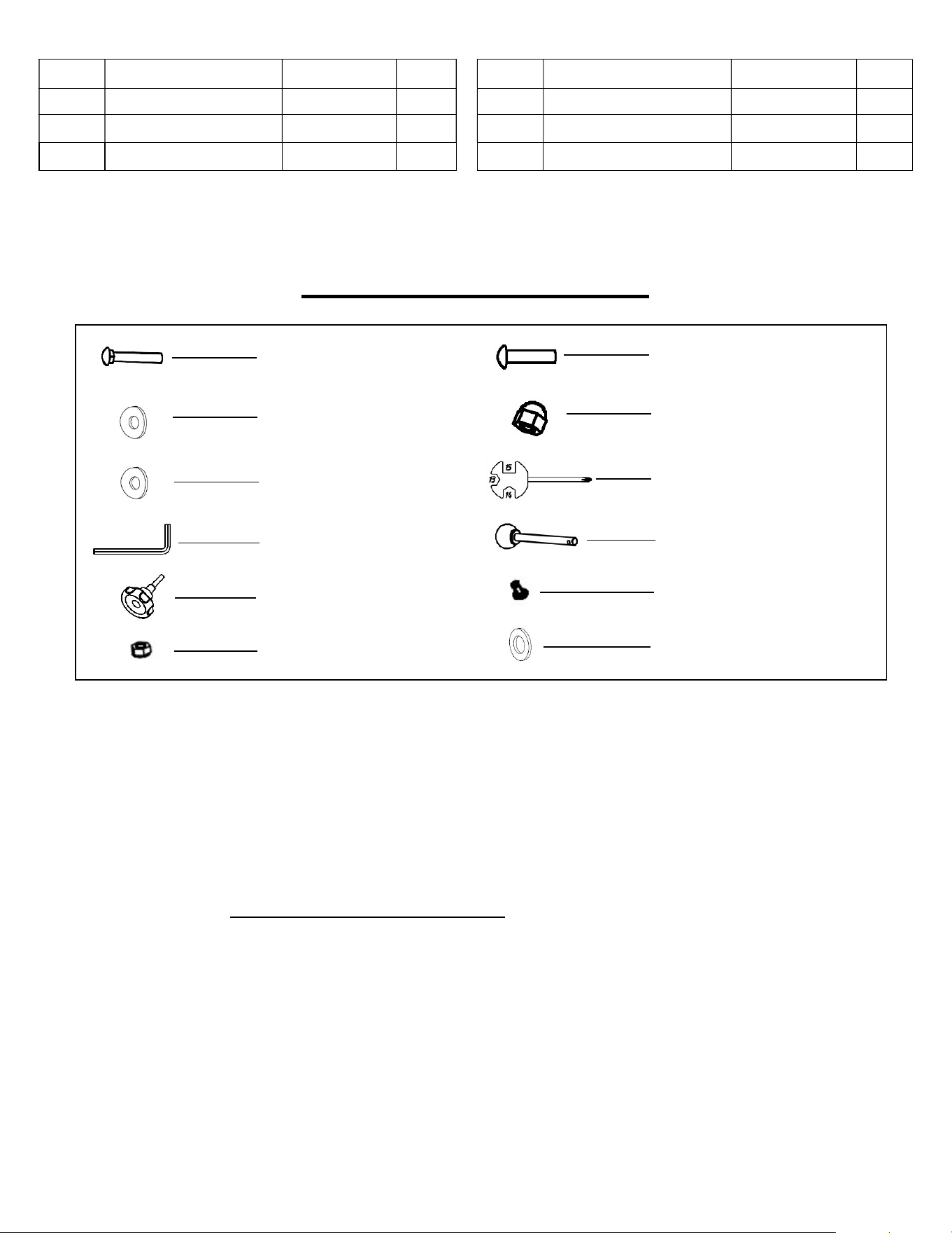
HARDWARE PACKAGE
Ordering Replacement Parts (U.S. and Canadian Customers only)
Please provide the following information in order for us to accurately identify the part(s) needed:
✓ The model number (found on cover of manual)
✓ The product name (found on cover of manual)
✓ The part number found on the “EXPLODED DIAGRAM” and “PARTS LIST” (found near the
front of the manual)
Please contact us at [email protected] or 1- 877 - 90SUNNY (877-907-8669).
#9 M8x50 4PCS
#12 M8x38 2PCS
#71 S13, 14, 15 1PC
#13 D8x1.5xR11 2PCS
#18 M8 4PCS
#19 D8x1.5xR22
4PCS
#72 S6 1PC
#17 1PC
#21 M8 3PCS
#20 D8 3PCS
5
ASSEMBLY INSTRUCTIONS
We value your experience using Sunny Health and Fitness products. For assistance with parts or
troubleshooting, please contact us at support@sunnyhealthfitness.com or 1-877-90SUNNY (877-907-
8669).
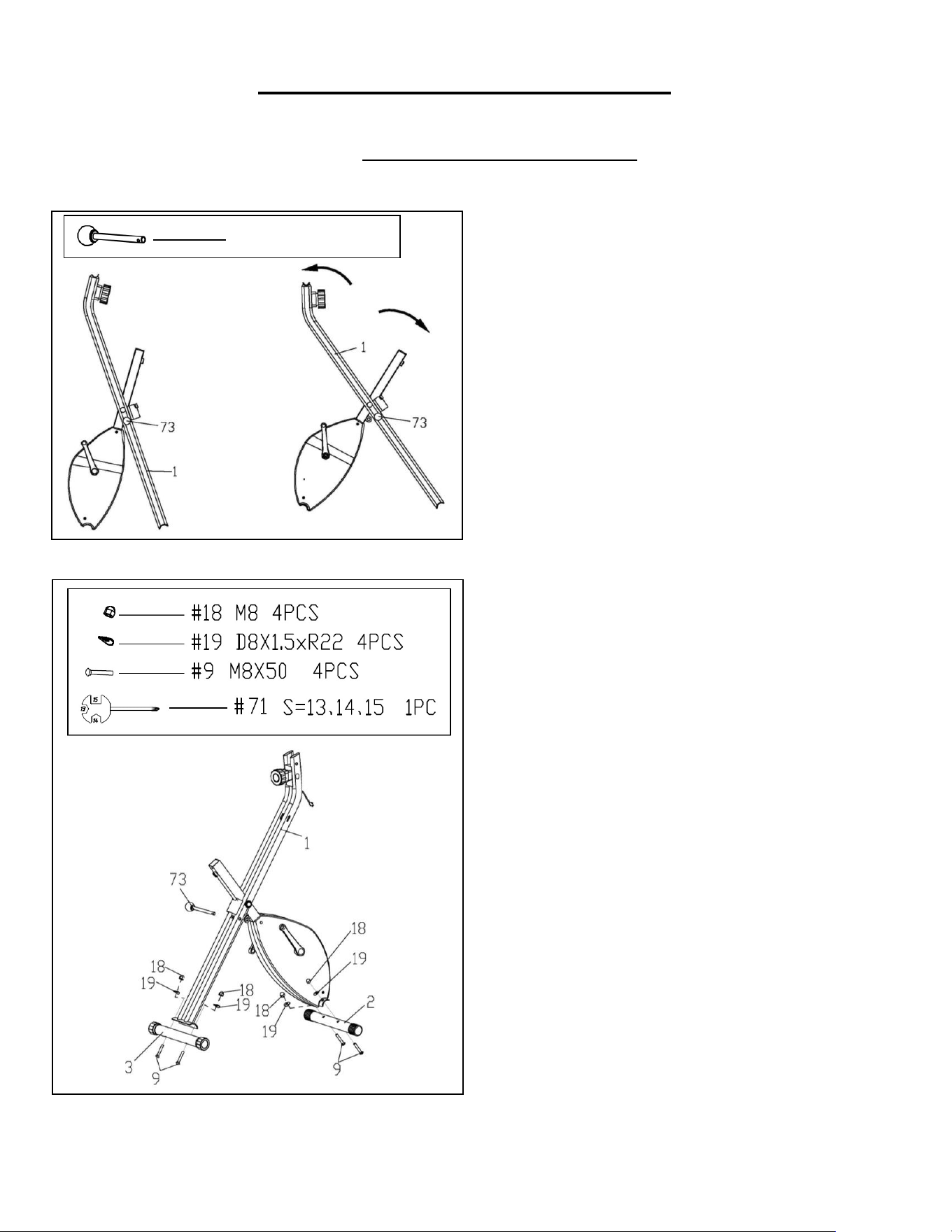
STEP 1:
Remove the preassembled Pull Pin (No.
73) from the Main Frame (No. 1).
Unfold the Main Frame (No. 1) and then
insert the Pull Pin (No. 73) back to the
Main Frame (No. 1).
STEP 2:
Attach the Front & Rear Stabilizer (No. 2 &
No. 3) to the Main Frame (No. 1) using 4
Carriage Bolts (No. 9), 4 Arc Washers
(No. 19) and 4 Cap Nuts (No. 18). Tighten
and secure with the Spanner (No. 71).
#73 1PC
6
We value your experience using Sunny Health and Fitness products. For assistance with parts or
troubleshooting, please contact us at support@sunnyhealthfitness.com or 1-877-90SUNNY (877-907-
8669).
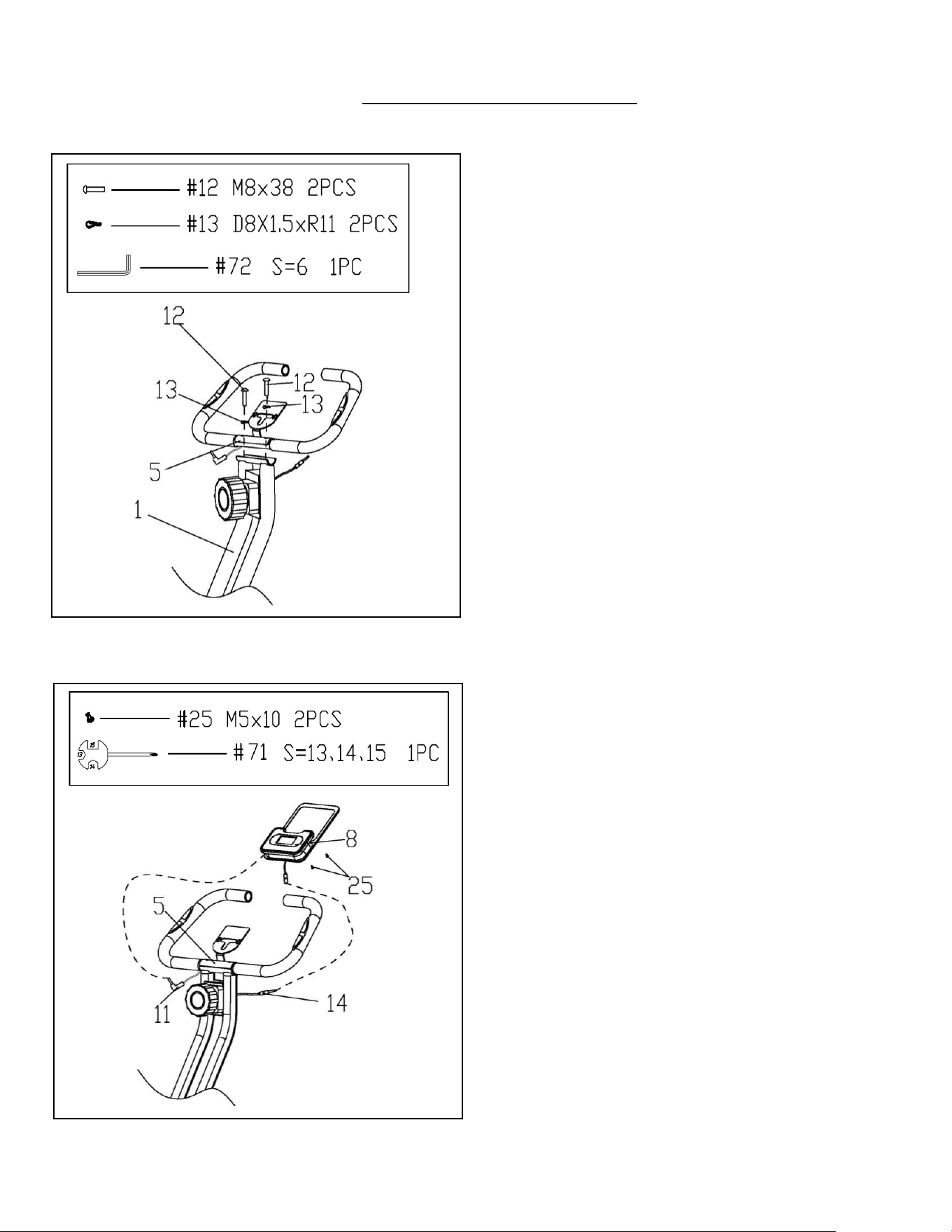
STEP
3
:
Attach the Handlebar (No. 5) to the Main
Frame (No. 1) using 2 Screws (No. 12) and
2 Arc Washers (No. 13). Tighten and
secure using Allen Wrench (No. 72).
STEP 4:
Open the battery cover from the back of
Meter (No. 8), then put 2 pcs batteries into
the battery compartment.
Remove 2 Screws (No. 25) from back of
the Meter (No. 8) by Spanner (No. 71),
then attach the Meter (No. 8) to the bracket
of the Handlebar (No. 5) using 2 Screws
(No. 25) that were just removed. Tighten
and secure with the Spanner (No. 71).
Connect the Pulse Wire (No. 11) to the jack
on the back of the Meter (No. 8).
Connect the Sensor Wire (No. 14) to the
wire from the Meter (No. 8).
7
We value your experience using Sunny Health and Fitness products. For assistance with parts or
troubleshooting,
please contact us at support@sunnyhealthfitness.com or 1-877-90SUNNY (877-907-
8669).
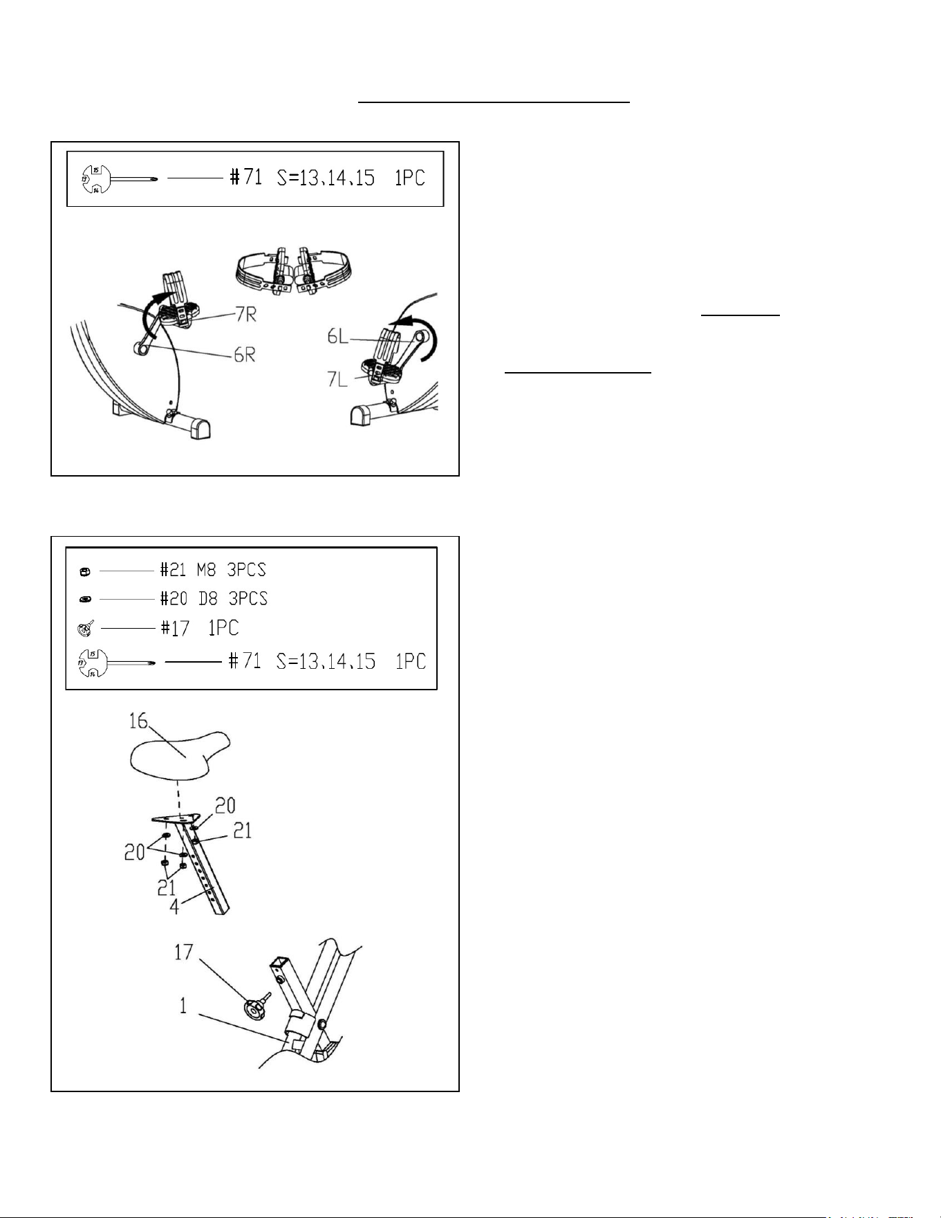
STEP
5
:
Attach Pedals (No. 7L/R) to the Cranks (No.
6L/R) using Spanner (No. 71).
NOTE: Make sure to attach Right Pedal (No.
7R), marked R, to the Right Crank (No. 6R).
It should be tightened clockwise. Attach the
Left Pedal (No. 7L), marked L, to the Left
Crank (No. 6L). It should be tightened
counter-clockwise. Attaching the Pedals (No.
7L/R) to the wrong Cranks (No. 6L/R) or
turning it the wrong direction will permanently
damage the crank and the pedal.
STEP 6:
Removed the preassembled 3 Flat Washers
(No. 20) and 3 Nylon Nuts (No. 21) from the
Seat (No. 16). Then attach the Seat (No. 16)
to the Seat Post (No. 4) using 3 Flat
Washers (No. 20) and 3 Nylon Nuts (No. 21)
that just removed. Tighten and secure with
the Spanner (No. 71).
Insert the Seat Post (No. 4) into the tube of
the Main Frame (No. 1). Adjust the Seat
Post (No. 4) to the proper height and secure
with the Knob (No. 17).
Assembly is now complete!
8
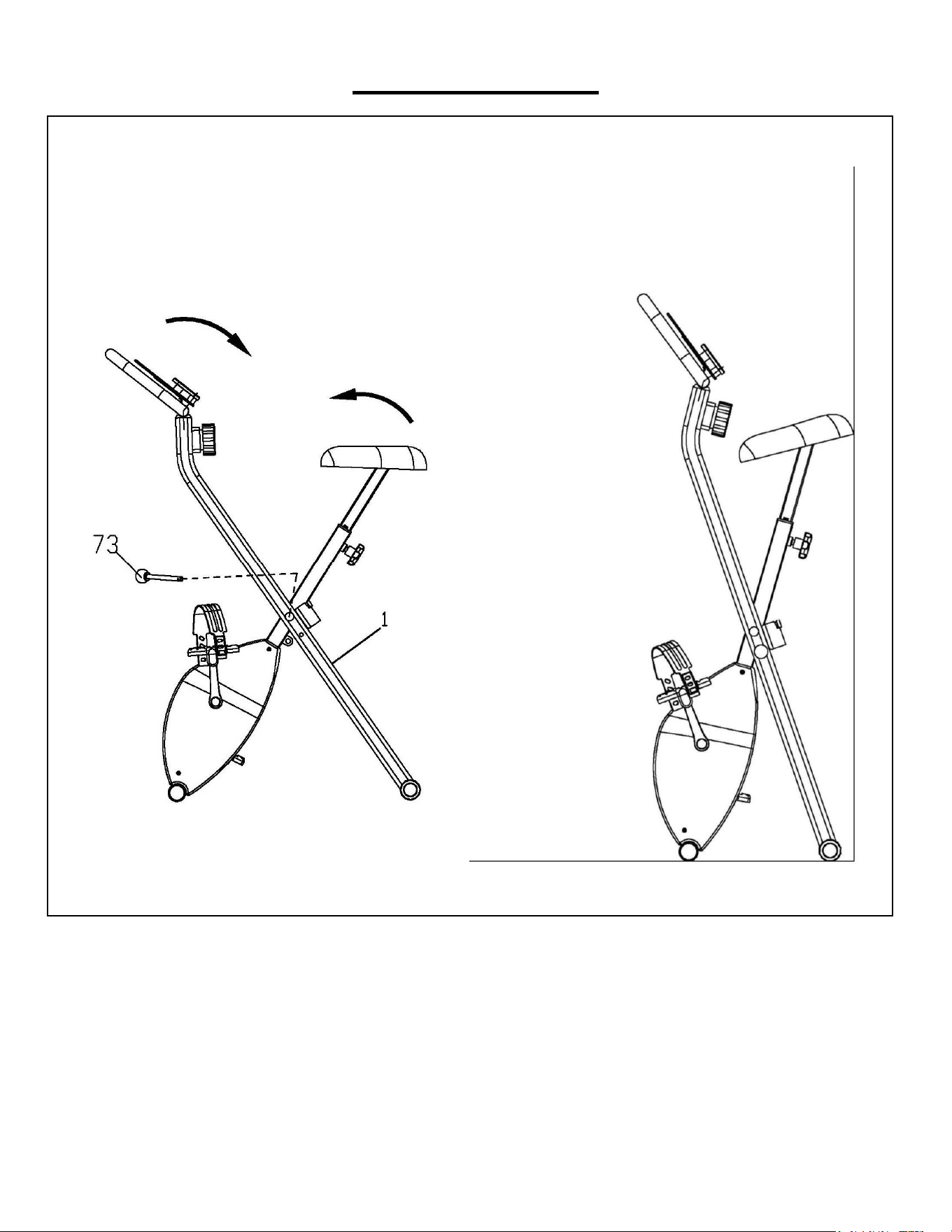
FOLDING GUIDE
Folding: Remove the Pull Pin (No. 73) from the Main Frame (No. 1), then fold the bike and move to
the side of the wall. Then insert the Pull Pin (No. 73) back to the Main Frame (No. 1) to fix the bike.
NOTE: Keep at least 2 feet of free space around the bike at all times when folding or unfolding. Be
cautious when folding or unfolding the bike as there are pinch hazards!
9
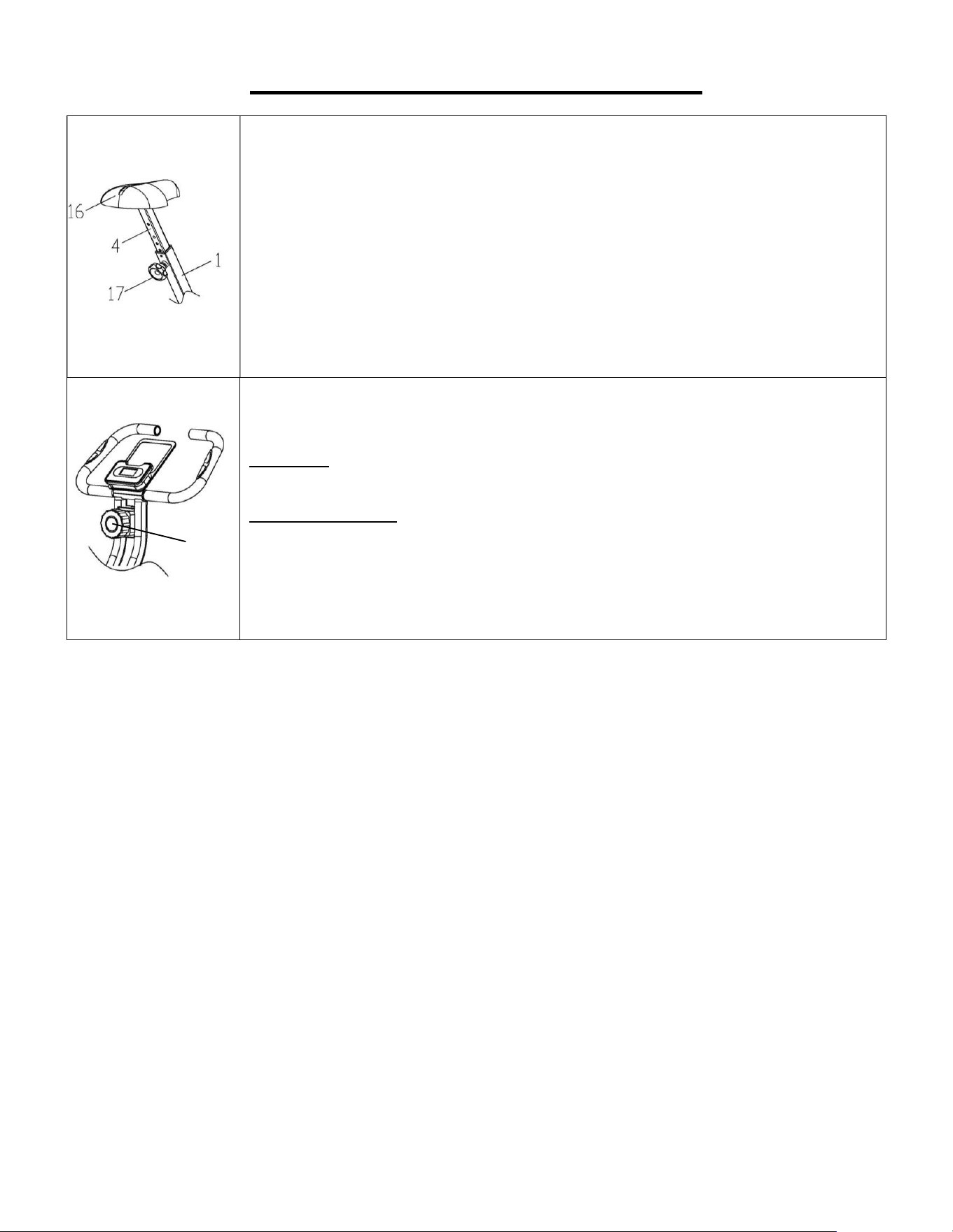
ADJUSTMENT INSTRUCTIONS
ADJUSTING THE SEAT POST
The Seat (No. 16) of this bike is adjustable up and down. To adjust the
height of the Seat Post (No. 4), loosen the Knob (No. 17) from the Main
Frame (No. 1) outward, then raise or lower the Seat Post (No. 4) to the
desired height. Once adjusted, re-insert and tighten the Knob (No. 17) to
secure the Seat Post (No. 4) in place.
ADJUSTING THE RESISTANCE
To increase the resistance level, turn the Tension Controller (No. 15)
clockwise.
To decrease the resistance level, turn the Tension Controller (No. 15)
counter-clockwise.
15
10
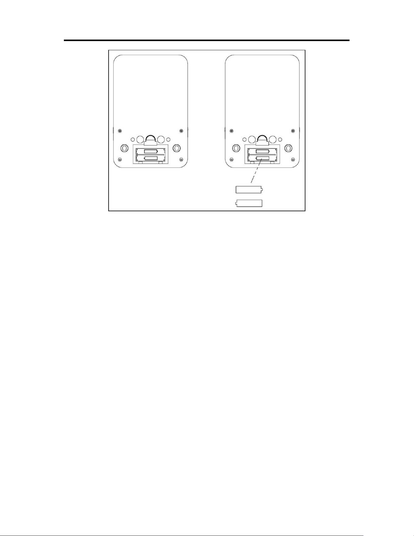
BATTERY INSTALLATION & REPLACEMENT
BATTERY INSTALLATION
The meter uses 2 AAA batteries. Open the battery cover from the back of meter, then put 2
batteries into the battery compartment. Make sure the (+) and (-) ends of the batteries are in the
correct position. Put the battery cover back.
BATTERY REPLACEMENT
If there is a problem with the display, try changing the batteries first. Remove the meter from the
bracket of the handlebar. Open the battery cover, remove the old batteries and replace with new
batteries. Make sure the (+) and (-) ends of the batteries are in the correct position. Put the
battery cover back. When changing batteries, always replace both with new batteries. Do not
mix old and new batteries. Dispose the batteries according to the laws and regulations of your
local region.
11
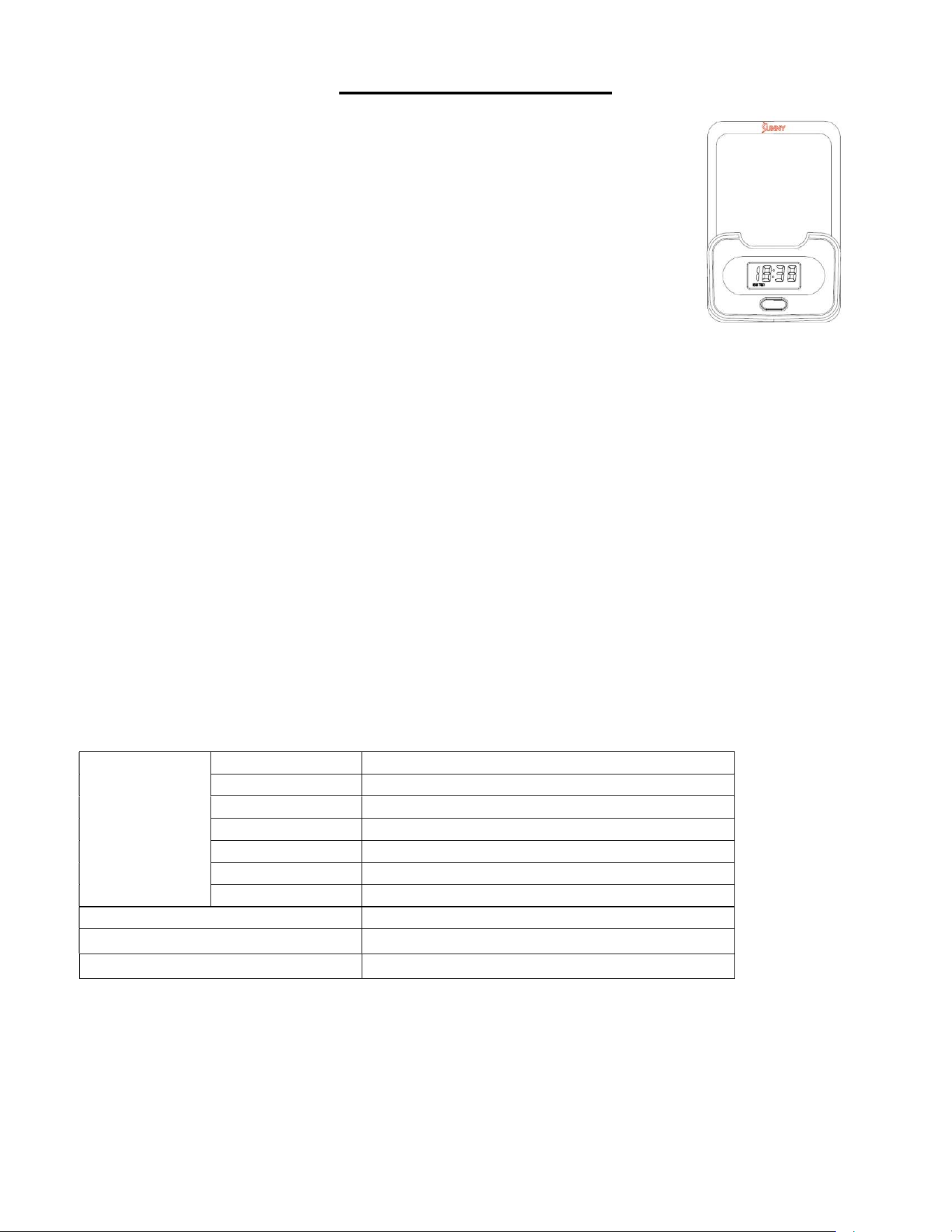
EXERCISE METER
KEY FUNCTION
●
This key lets you to select and lock on to a particular function you want.
SCAN
→
TIME
→
SPEED
→
DIST
→
CALORIES(CAL)
→
TOTAL DIST(ODO)
→
PULSE RATE
●
Press and hold with 3 seconds to reset the value to zero (except ODO).
.
SET SLEEP MODE
●
The system will enter sleep mode automatically when the sensor has no signal
input or no keys are pressed for approximately 4 minutes.
●
The system will turns on again when the MODE key is pressed or there is a signal input from
the sensor.
FUNCTION
1. SCAN: Automatically scans through and display each function in the sequence below every 6 seconds.
TIME
→
SPEED
→
DIST
→
CALORIES(CAL)
→
ODO
→
PULSE RATE
2. TIME: Display the total exercise time from start to finish.
3. SPEED: Display current exercise speed during exercise.
4. DISTANCE: Display distance of each exercise from start to finish.
5. CALORIE: Display total calories burned during each exercise from start to finish.
6. ODO: Display total distance from all the workout. If the battery is replaced, the value returns to zero.
7. PULSE RATE: Display current pulse rate during exercise. The measurement value cannot be regarded
as the basis of medical treatment.
SPECIFICATIONS
Version 1.0
FUNCTION
SCAN
Every
6
S
econ
d
s
T
IME
0:00
-
99:59
MIN
:
SEC
SPEED 0~999.9 MPH (MILE/Hour)
DIST
0~9999
MILE
ODO 0~9999 MILE
CAL
0~9999
KCAL
PULSE RATE
40~240
BPM
BATTERY
2
-
AAA
Operating temperature
0 ~ 40
℃
(32°F - 104°F)
Storage temperature
-10 ~ 60
℃
(14°F - 140°F)

14