1
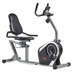
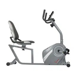
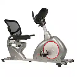
POWERSYNC SELF-POWERED
RECUMBENT BIKE
SF-RB4880
USER MANUAL
IMPORTANT! Please retain owner’s manual for maintenance and adjustment instructions.
Your satisfaction is very important to us, PLEASE DO NOT RETURN UNTIL YOU HAVE
CONTACTED US: [email protected] or 1-877-90SUNNY (877-907-8669).

2
IMPORTANT SAFETY INFORMATION
We thank you for choosing our product. To ensure your safety and health, please use this equipment
correctly. It is important to read this entire manual before assembling and using the equipment. Safe
and effective use can only be achieved if the equipment is assembled, maintained and used properly.
It is your responsibility to ensure that all users of the equipment are informed of all warnings and
precautions.
1. Before starting any exercise program, you should consult your physician to determine if you have
any medical or physical conditions that could put your health and safety at risk, or prevent you
from using the equipment properly. Your physician’s advice is essential if you are taking
medication that affects your heart rate, blood pressure or cholesterol level.
2. Be aware of your body’s signals. Incorrect or excessive exercise can damage your health. Stop
exercising if you experience any of the following symptoms: pain, tightness in your chest,
irregular heartbeat, shortness of breath, lightheadedness, dizziness or feelings of nausea. If you
do experience any of these conditions, you should consult your physician before continuing with
your exercise program.
3. Keep children and pets away from the equipment. The equipment is designed for adult use only.
4. Use the equipment on a solid, flat level surface with a protective cover for your floor or carpet.
To ensure safety, the equipment should have at least 4 feet (1.2 M) of free space all around it.
5. Ensure that all nuts and bolts are securely tightened before using the equipment. The safety of
the equipment can only be maintained if it is regularly examined for damage and/or wear and
tear.
6. Always use the equipment as indicated. If you find any defective components while assembling
or checking the equipment, or if you hear any unusual noises coming from the equipment during
exercise, discontinue use of the equipment immediately and do not use until the problem has
been rectified.
7. Wear suitable clothing while using the equipment. Avoid wearing loose clothing that may become
entangled in the equipment.
8. Do not place fingers or objects into the moving parts of the equipment.
9. The maximum weight capacity of this unit is 300 pounds (135 KG).
10. The equipment is not suitable for therapeutic use.
11. To avoid bodily injury and/or damage to the product or property, proper lifting and moving is
required.
12. Your product is intended for use in cool, dry conditions. You should avoid storage in extreme
cold, hot or damp areas as this may lead to corrosion and other related problems.
13. This equipment is designed for indoor and home use only. It is not intended for commercial use!

3
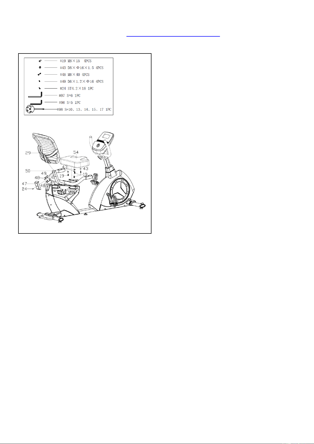
EXPLODED DIAGRAM
4
HARDWARE PACKAGE
Ordering Replacement Parts (U.S. and Canadian Customers only)
Please provide the following information in order for us to accurately identify the part(s) needed:
The model number (found on cover of manual)
The product name (found on cover of manual)
The part number found on the “EXPLODED DIAGRAM” and “PARTS LIST” (found near the front
of the manual)
Please contact us at [email protected] or 1- 877 - 90SUNNY (877-907-8669).
#26 M8x90 2PCS
#48 M6X40 4PCS
#24 ST4.2X18 3PCS
#33 1PC
#98 S=10,13,14,15,17 1PC
#20 D8xΦ20 2PCS
#49 D6X1.2XΦ16 4PCS
#32 1PC
#34 D8XΦ13X1.5 1PC
#96 S=5 1PC
#97 S=6 1PC
5
PARTS LIST
NO.
Description
Spec.
Qty.
NO.
Description
Spec.
Qty.
1
Main Frame
1
35
Foam Grip
2
2
Front Stabilizer
1
36
Pulse Extension Wire 1
2
3
Rear Stabilizer
1
37
Pulse Extension Wire 2
2
4
Handlebar Post
1
38
Meter
1
5
Handlebar
1
39
Axle
1
6
Nylon Nut
M8
6
40
Screw
M6X10
4
7
Flat Washer
D8XΦ16X1.5
7
41
Handle
1
8
Wheel
2
42
Handle Grip
1
9
Screw
M8X40XL12
2
43
Flat Washer
D8XΦ16X1.5
12
10
Oval Cap 1
2
44
Pulse Extension Wire 3
2
11
Hex Nut
M10
5
45
Pulse Wire
2
12
Adjusting Pad
5
46
Seat Fixed Bracket
1
13
Bolt
M8XL58
4
47
Protective Cover
1
14
Spring Washer
D8
8
48
Screw
M6X40
4
15
Arc Washer
D8X2XΦ25X
R39
4
49
Flat Washer
D6X1.2XΦ16
4
16
Oval Cap 2
2
50
Seat Bracket
1
17L/R
Crank
1 pr.
51
Square Cap
2
18L/R
Pedal
1 pr.
52
Pulse Foam Grip
2
19
Screw
M8X15
11
53
Round Cap
2
20
Arc Washer
D8xΦ20
2
54
Seat
1
21
Sensor Wire
1
55
Axle Spring Washer
1
22
Extension Wire
1
56
Crank Cover
2
23L/R
Front Cover
1 pr.
57
Flange Bolt
2
24
Screw
ST4.2X18
34
58L/R
Chain Cover
1 pr.
25a/b
Handlebar Cover
1 pr.
59
Flange Nut
M10X1
2
26
Bolt
M8X90
2
60
Adjustable Chain Bolt
2
27
Lifting Handle
1
61
Adjustable Chain U
Mat
2
28
Screw
M8X12
16
62
Hex Nut
M6
2
29
Backrest
1
63
Conical Thin Nut
2
30
Round Cap
2
64
Tension Wire
1
31
Screw
M5X10
4
65
Tension Spring
1
32
Plastic Handle
Screw
1
66
Flywheel Axle
1
33
Sleeve
1
67
Flywheel
1
34
Flat Washer
D8XΦ13X1.5
1
68
Motor
1
6
NO.
Description
Spec.
Qty.
NO.
Description
Spec.
Qty.
69
Axle Spring
Washer
1
85
Handle Bracket
1
70
Bearing
2
86
Big Alloy Sleeve
1
71
Nylon Nut
M10
1
87
Upper Holder Block
1
72
Belt Pulley
1
88
Idler Wheel
1
73
Center Axle
1
89
Axle Spring Washer
1
74
Belt
1
90
Eccentric Wheel
1
75
Small Belt Pulley
1
91
Nylon Nut
M8
4
76
Sensor
1
92
Wheel
4
77
Cushion
2
93
Wheel Sleeve
4
78L/R
Protective Cover
1 pr.
94
Bolt
4
79
Square Cap 1
1
95
Small Alloy Sleeve
1
80
Square Cap 2
1
96
Allen Wrench
S=5
1
81
Guide Rail
1
97
Allen Wrench
S=6
1
82
Battery Holder
1
98
Spanner
S=10,13,14,15,
17
1
83
Voltage Stabilizer
1
99
Audio Cable
1
84
Idler Connecting
Rod
1
7
ASSEMBLY INSTRUCTIONS
We value your experience using Sunny Health and Fitness products. For assistance with parts or
troubleshooting, please contact us at suppo[email protected] or 1-877-90SUNNY (877-
907-8669).
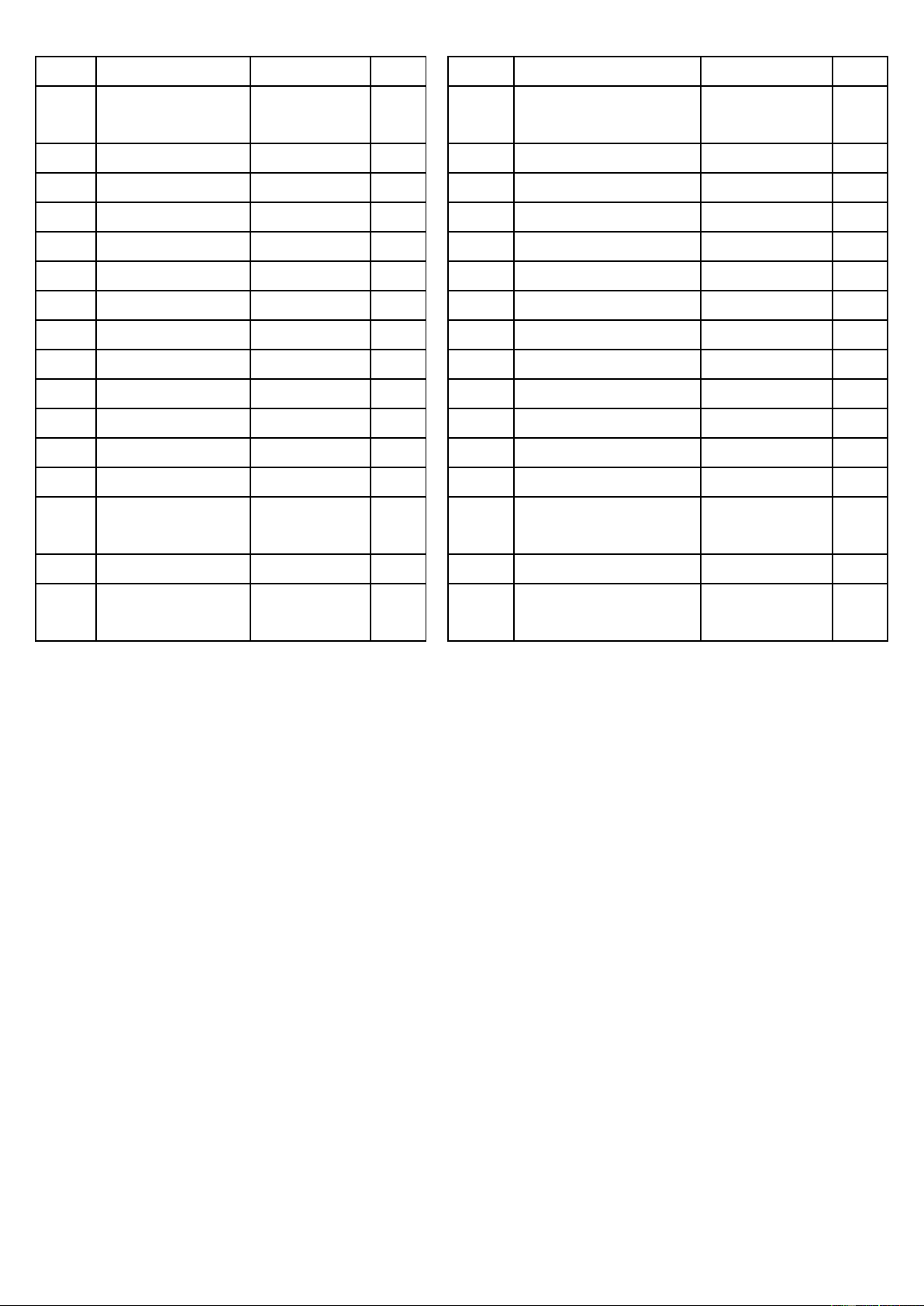
STEP 1:
Attach the Lifting Handle (No. 27) to the Rear
Stabilizer (No. 3) with 2 Bolts (No. 26) and 2 Arc
Washers (No. 20) using Allen Wrench (No. 97).
Remove 2 Shipping Tubes (A), 4 Bolts (No. 13),
4 Spring Washers (No. 14) and 4 Arc Washers
(No. 15) from the Main Frame (No. 1) using
Allen Wrench (No. 97).
Attach the Front & Rear Stabilizer (No. 2 & 3) to
the Main Frame (No. 1) with 4 Bolts (No. 13), 4
Spring Washers (No. 14) and 4 Arc Washers
(No. 15) that were just removed. Tighten and
secure with Allen Wrench (No. 97).
Note: You may discard shipping tubes or save
them in case you’d like to repackage the item in
the future.
STEP 2:
Remove 4 Screws (No. 19), 4 Spring Washers
(No. 14) and 4 Flat Washers (No. 7) from the
Main Frame (No. 1) using Allen Wrench (No.
97).
Connect the Sensor Wire (No. 21) with
Extension Wire (No. 22), and then connect 2
Pulse Extension Wires 1 (No. 36) with 2 Pulse
Extension Wires 2 (No. 37).
Attach the Handlebar Post (No. 4) to the Main
Frame (No. 1) with 4 Screws (No. 19), 4 Spring
Washers (No. 14) and 4 Flat Washers (No. 7)
that were just removed. Tighten and secure with
Allen Wrench (No. 97).
Note: Do not cut or pinch any wire when
attaching the Handlebar Post (No. 4).
Attach the Front Covers (No. 23L/R) to the Main
Frame (No. 1) with 3 Screws (No. 24). Tighten
and secure with Spanner (No. 98).
8
We value your experience using Sunny Health and Fitness products. For assistance with parts or
troubleshooting, please contact us at support@sunnyhealthfitness.com or 1-877-90SUNNY (877-
907-8669).
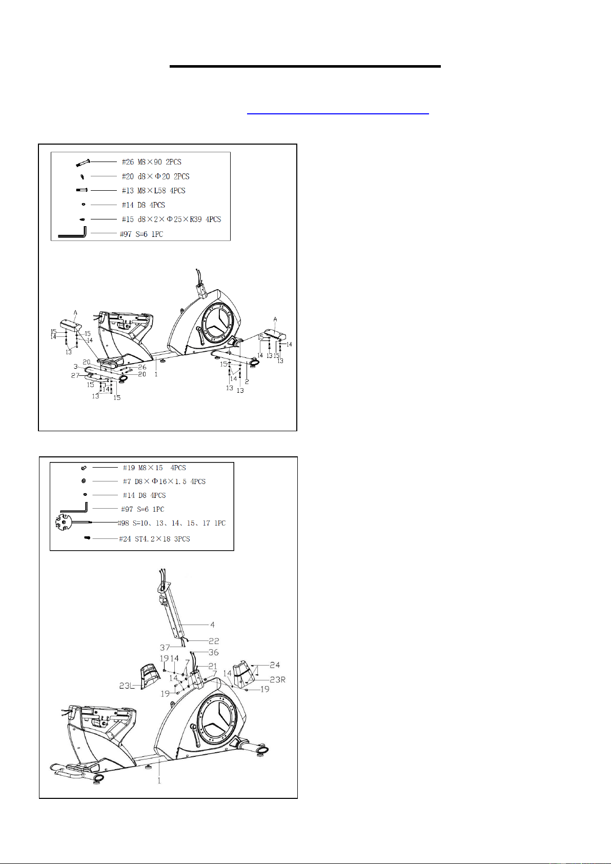
STEP 3:
Remove the Screw (No. 24) with Spanner (No.
98) to separate Handlebar Cover (No. 25a) and
Handlebar Cover (No. 25b). (Figure A)
Remove the Sleeve (No. 33) and Flat Washer
(No. 34) from the Plastic Handle Screw (No.
32).
Attach the Handlebar (No. 5) to the Handlebar
Post (No. 4), adjust the Handlebar (No. 5) to the
suitable position, and then insert the Plastic
Handle Screw (No. 32) through Handlebar
Cover (No. 25a), Sleeve (No. 33) and Flat
Washer (No. 34). Tighten the Plastic Handle
Screw (No. 32) to secure.
STEP 4:
Remove 4 Screws (No. 31) from the back of the
Meter (No. 38) using Spanner (No. 98).
Connect the 2 Pulse Extension Wires 2 (No. 37)
and Extension Wire (No. 22) with corresponding
wires of Meter (No. 38).
Note: Make sure all the wires are in the tube of
the Handlebar Post (No. 4).
Attach the Meter (No. 38) to the Handlebar Post
(No. 4) with 4 Screws (No. 31) that were just
removed. Tighten and secure with Spanner (No.
98).
Lock the Handlebar Cover (No. 25b) to the
Handlebar Post (No. 4) with the Screw (No. 24)
using Spanner (No. 98).
Figure A
9
We value your experience using Sunny Health and Fitness products. For assistance with parts or
troubleshooting, please contact us at support@sunnyhealthfitness.com or 1-877-90SUNNY (877-
907-8669).
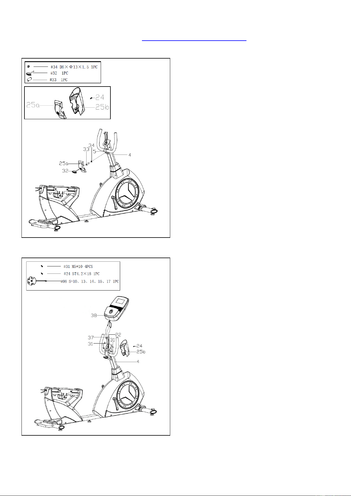
STEP 5:
Attach the Pedals (No. 18L/R) to Cranks (No.
17L/R).
NOTE: Make sure to attach Right Pedal (No.
18R), marked (R), to the Right Crank (No. 17R).
It should be tightened clockwise. Attach the Left
Pedal (No. 18L), marked (L), to the Left Crank
(No.17L). It should be tightened
counterclockwise. Attaching the Pedals (No.
18L/R) to the wrong Cranks (No. 17L/R) or
turning it the wrong direction can damage the
Cranks (No. 17L/R).
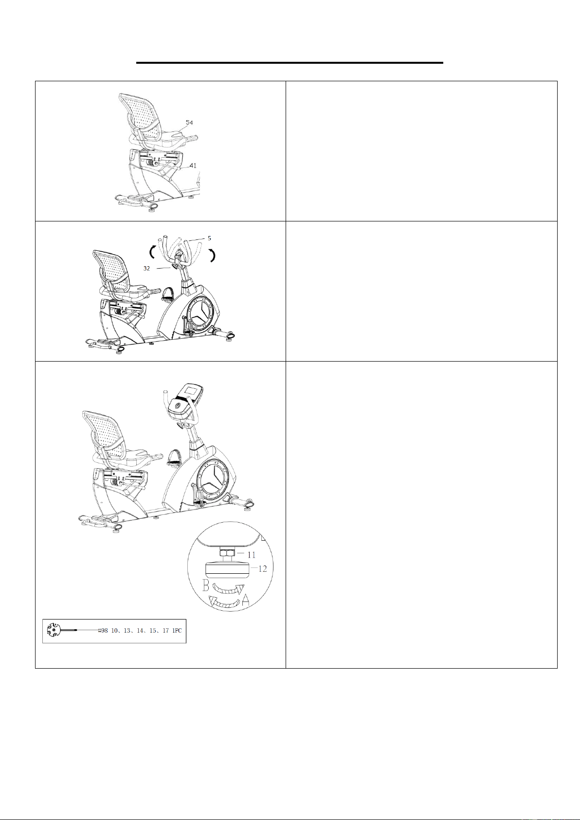
STEP 6:
Remove 4 Screws (No. 28) and 4 Flat Washers
(No. 43) from the Seat Fixed Bracket (No. 46)
using Allen Wrench (No. 96).
Attach the Seat Bracket (No. 50) to the Seat
Fixed Bracket (No. 46) using 4 Screws (No. 28)
and 4 Flat Washers (No. 43) that were just
removed. Tighten and secure with Allen Wrench
(No. 96).
Note: There are 3 positions on the Seat Fixed
Bracket (No. 46), numbered 1, 2, and 3, that you
can install the Seat Bracket (No. 50). Adjust the
seat position to suit your height. (Figure B)
Connect the 2 Pulse Wires (No. 45) with 2 Pulse
Extension Wires 3 (No. 44) on the Main Frame
(No. 1).
Remove 2 Screws (No. 40) from the Axle (No.
39). Attach the Handle (No. 41) to the Axle (No.
39) with 2 Screws (No. 40) that were just
removed. Tighten and secure with Allen Wrench
(No. 96).
T
i
g
Figure B
10
We value your experience using Sunny Health and Fitness products. For assistance with parts or
troubleshooting, please contact us at support@sunnyhealthfitness.com or 1-877-90SUNNY (877-
907-8669).
STEP 7:
Remove 4 Screws (No. 19) and 4 Flat Washers
(No. 43) from the Seat (No. 54) using Allen
Wrench (No. 97).
Attach the Seat (No. 54) to the Seat Bracket (No.
50) with 4 Screws (No. 19) and 4 Flat Washers
(No. 43) that were just removed, using Allen
Wrench (No. 97).
Remove the Screw (No. 24) from the Seat
Bracket (No. 50) using the Spanner (No. 98).
Attach the Backrest (No. 29) to the Seat Bracket
(No. 50) with 4 Screws (No. 48) and 4 Flat
Washers (No. 49) using Allen Wrench (No. 96).
Attach the Protective Cover (No. 47) to the Seat
Bracket (No. 50) with the Screw (No. 24) using
the Spanner (No. 98).
The assembly is now complete!
t
i
g
h
t
e
n
b
y
h
a
n
d
f
i
r
s
t
,
t
11
ADJUSTMENTS & USAGE GUIDE
ADJUSTING THE SEAT POSITION
To move the Seat (No. 54) forward or backward,
while seated on the bike, put your feet on the floor.
Pull the Handle (No. 41) towards you. Move the
Seat (No. 54). Push the Handle (No. 41) forward
to secure.
ADJUSTING THE HANDLEBAR
To move the Handlebar (No. 5) forward or
backward, loosen the Plastic Handle Screw (No.
32). Adjust the Handlebar (No. 5) to a suitable
position, and tighten the Plastic Handle Screw
(No. 32) to secure.
ADJUSTING THE LEVEL
In order to achieve a smooth and comfortable ride,
you must ensure that the stability of the bike is
secured. If you notice that the bike is unbalanced
during use, you should adjust the foot levelers
located beneath the front and rear stabilizers. To do
so, use Spanner (No. 98) to loosen Hex Nut (No.
11) by turning it clockwise (direction A). With the
nuts loosened, rotate Adjusting Pad (No. 12) until
it sits level with the surface that the bike is on.
When you have finished adjusting the foot leveler,
use Spanner (No. 98) to re-tighten the Hex Nut
(No. 11) by turning it counter-clockwise (direction
B). If required, repeat this process to adjust the
remaining feet.
12
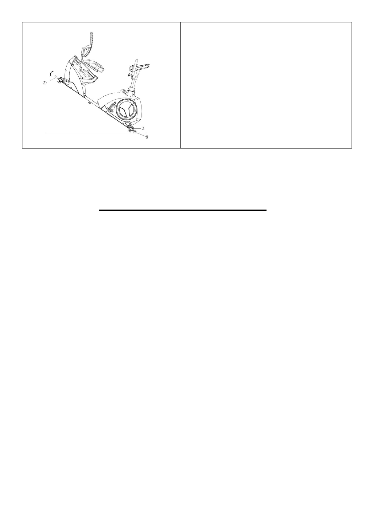
MOVING THE BIKE
Lift the bike by the Lifting Handle (No. 27) until the
Wheels (No. 8) on the Front Stabilizer (No. 2)
touch the floor. Now you can move the bike.
OPERATING INSTRUCTIONS
The Powersync Self-Powered Recumbent Bike can generate its own power. When you pedal the
bike, it generates power to power the meter and charge a device.
The first time you use the bike or if you have not used the bike in a while, you have to pedal for
about 5 minutes before there is enough power for the meter to display. When you stop pedaling, the
meter will shut off.
13
EXERCISE METER
DISPLAY FUNCTIONS
ITEM
DESCRIPTION
TIME
Count up - No preset target, time will count up from 00:00 to 99:59.
Count down - If training with preset time, time will count down from preset value to
00:00.
Each preset increment or decrement is 1 minute between 00:00 to 99:00.
SPEED
Displays current training speed. Display range 0.0~99.9 KM/H or ML/H.
RPM
Displays the Rotation Per Minute. Display range 0~999 revolutions.
DISTANCE
Accumulates total distance from 0.00 to 99.99 KM or ML. The user may preset target
distance value by using UP/DOWN key.
Each preset increment or decrement is 1 KM or ML between 0.00 to 99.90.
CALORIES
Accumulates calories consumption during training from 0 to maximum 9999 KCAL.
(This data is a rough guide for comparison of different exercise sessions which cannot
be used in medical treatment.)
The user may preset target calories value by using UP/DOWN key.
PULSE
User may set up target pulse from P - 30 to 230. Meter buzzer will beep when actual
heart rate overs the target value during workout.
WATTS
Display current workout watts. Display range 0~999; setting range 10~350.
MANUAL
Manual mode workout.
BEGINNER
Beginner mode workout. Beginner 1 – 4.
ADVANCE
Advance mode work out. Advance 1 – 4.
SPORTY
Sporty mode work out. Sporty 1 – 4.
CARDIO
Target HR training mode.
WATT
PROGRAM
WATT constant training mode.
14
KEY FUNCTION
OPERATION
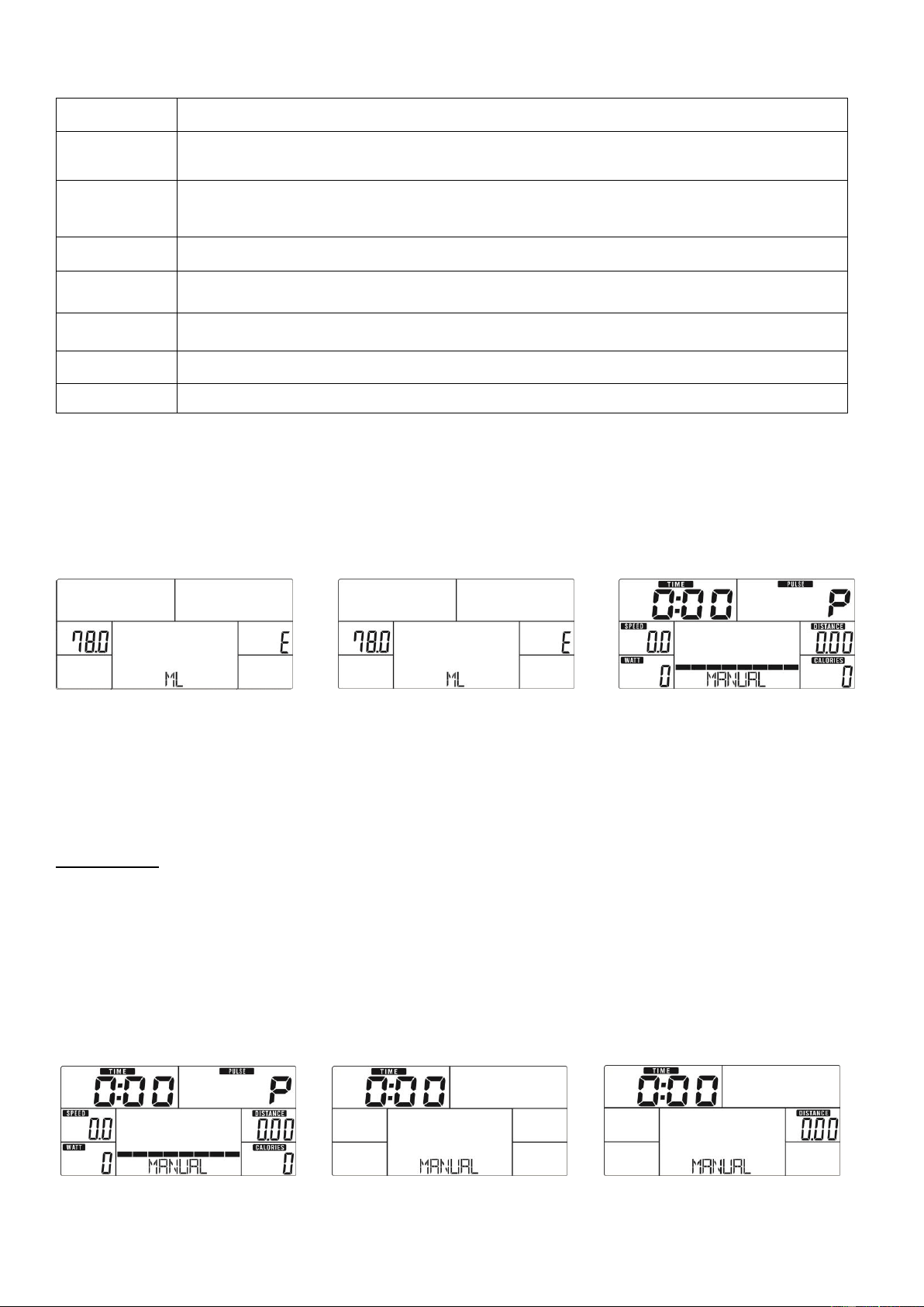
POWER ON
Meter will power on and display all segments on LCD for 2 seconds (Drawing 1). Then, it displays wheel
diameter (78.0) and ML (Drawing 2). After that, the meter goes to Standby mode (Drawing 3).
Drawing 1 Drawing 2 Drawing 3
WORKOUT SELECTION
In stop mode, use + or - to select Workout: Manual Beginner Advance Sporty Cardio Watt
Manual Mode
1. Use + or - to select workout program, choose Manual Mode and press MODE to confirm (Drawing 4).
2. Use + or - to set TIME (Drawing 5), DISTANCE (Drawing 6), CALORIES (Drawing 7), PULSE (Drawing
8) and press MODE to confirm.
3. Press START/STOP key to start workout. Use + or - to adjust resistance level during workout. Resistance
level displays in WATT window. If you do not change the resistance level, after 3 seconds, it will switch
to display WATT (Drawing 9).
4. Press START/STOP key to stop workout. Press RESET to reverse to main menu.
Drawing 4 Drawing 5 Drawing 6
ITEM
DESCRIPTION
+
Increase resistance level by turning the button clockwise.
Select setting.
-
Decrease resistance level by turning the button counter clockwise.
Select setting.
Mode
In stop mode, press to confirm all setting or selection and enter program.
Reset
Press and hold for 2 seconds, meter will reboot and start from user setting.
In stop mode, press to go back to main menu.
Start/ Stop
Start or stop workout.
Recovery
Test heart rate recovery status.
Body fat
In stop mode, press it for body fat measurement
15
Drawing 7 Drawing 8 Drawing 9
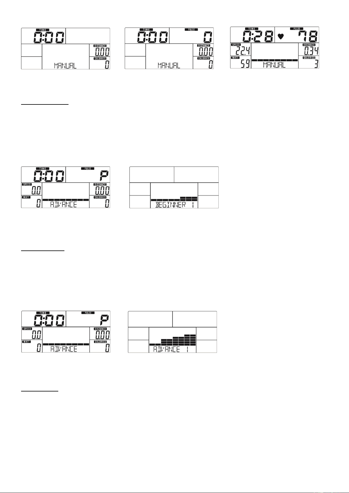
Beginner Mode
1. Press START/STOP in any mode, then press RESET go to main menu. When MANUAL is flashing, use
+ or - to select workout program, choose Beginner Mode and press MODE to confirm (Drawing 13).
2. Use + or - to select Beginner program 1~4 and press MODE to confirm (Drawing 14).
3. Use + or - to set TIME.
4. Press START/STOP key to start workout. Use + or - to adjust resistance level during workout.
5. Press START/STOP key to stop workout. Press RESET to return to main menu.
5.
6.
7.
8.
Drawing 13 Drawing 14
Advance Mode
1. Press START/STOP in any mode, then press RESET go to main menu. When MANUAL is flashing, use
+ or - to select workout program, choose Advance Mode and press MODE to confirm (Drawing 15).
2. Use + or - to select Advance program 1~4 (Drawing 16) and press MODE to confirm.
3. Use + or - to set TIME.
4. Press START/STOP key to start workout. Use + or - to adjust resistance level during workout.
5. Press START/STOP key to stop workout. Press RESET to return to main menu.
Drawing 15 Drawing 16
Sporty Mode
1. Press START/STOP no matter in any mode, then press RESET go to main menu. When MANUAL is
flashing, use + or - to select workout program, choose Sporty Mode and press MODE to confirm (Drawing
17).
2. Use + or - to select Sporty program 1~4 (Drawing 18) and press MODE to confirm.
3. Use + or - to set TIME.
4. Press START/STOP key to start workout. Use + or - to adjust resistance level during workout.
5. Press START/STOP key to stop workout. Press RESET to return to main menu.
16
Drawing 15
Drawing 17 Drawing 18
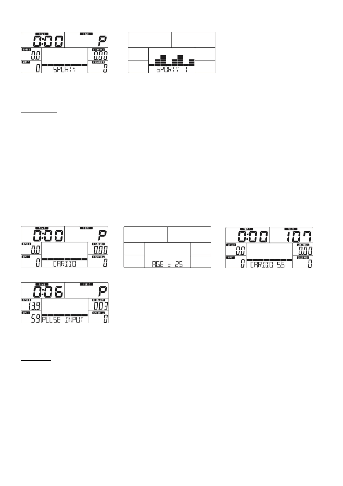
Cardio Mode
1. Press START/STOP in any mode, then press RESET go to main menu. When MANUAL is flashing, use
+ or - to select workout program, choose cardio and press MODE to confirm (Drawing 19).
2. Use + or - to set Age (Drawing 20, default: 25, range: 1-99), then press MODE to go to different CARDIO
program selection.
3. Use + or - to select CARDIO 55%, 75%, 90% or TAG (Drawing 21, default: 100), and press MODE to
confirm. When select 55%, 75%, 90%, press MODE to enter TIME setting. If you select TAG (TARGET
H.R.), press MODE to enter PULSE setting.
4. Use + or - to set workout TIME or PULSE.
Note: If no pulse input to meter 6 seconds after starting workout, LCD will display “PULSE INPUT” for
reminder (Drawing 22).
5. Press START/STOP key to start or stop workout. Press RESET to return to main menu.
Drawing 19 Drawing 20 Drawing 21
Drawing 22
Watt Mode
1. Press START/STOP in any mode, then press RESET go to main menu. When MANUAL is flashing, use
+ or - to select workout program, choose WATT Mode and press MODE to confirm (Drawing 23).
2. Use + or - to set WATT (Drawing 24, default:120), and press MODE to enter TIME setting.
3. Use+ or - to set TIME. Press START/STOP key to start workout. During workout, system will adjust
resistance level according to input value and workout status (Drawing 25). Use + or - to adjust WATT
level.
4. Press START/STOP key to stop workout. Press RESET to return to main menu.
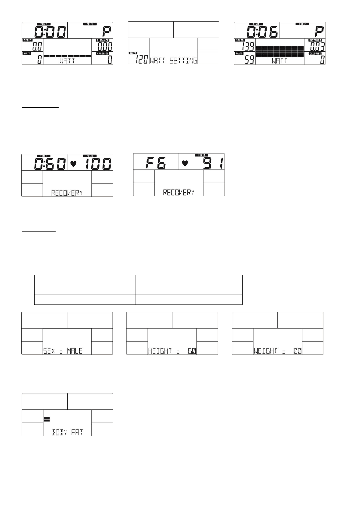
17
Drawing 23 Drawing 24 Drawing 25
RECOVERY
After exercising for a period, keep holding pulse sensors and press RECOVERY key.
All function display will stop except “TIME” starts counting down from 00:60 to 00:00 (Drawing 25). Screen
will display your heart rate recovery status with the F1, F2…. to F6. F1 is the best, F6 is the worst (Drawing
26). User may keep exercising to improve the heart rate recovery status. Press the RECOVERY key again
to return the main display.
Drawing 25 Drawing 26
BODY FAT
1. In STOP mode, press the BODY FAT key to start body fat measurement. Meter will prompt to input user
GENDER, HEIGHT, WEIGHT, then begin to measure.
2. Use + or - to set GENDER (Drawing 27) and press MODE to confirm. Repeat to set HEIGHT (Drawing
28) and WEIGHT (Drawing 29).
GENDER
MALE/FEMALE
HEIGHT
100-200 CM /40 - 80 INCH
WEIGHT
20 – 150 KG / 40 - 350 LBS
Drawing 27 Drawing 28 Drawing 29
3. During measuring, you have to hold both hands on the pulse sensors. And the LCD will display “=”
(Drawing 30) for 8 seconds until meter finish measuring.
Drawing 30
4. LCD will display BODY FAT advice symbol, BODY FAT percentage (Drawing 31), BMI (Drawing 32) for
30 seconds.
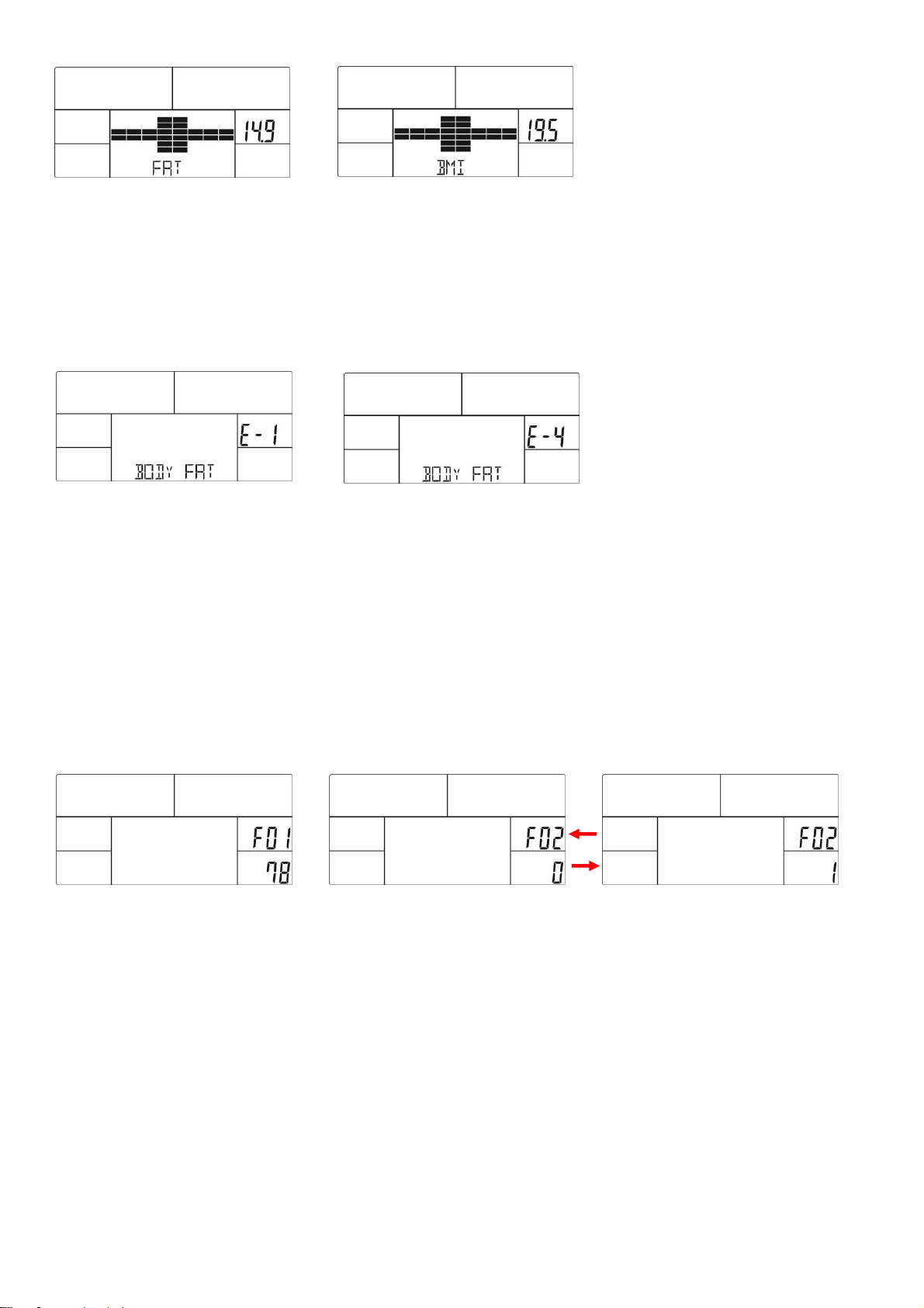
18
Drawing 31 Drawing 32
5. During personal profile setting, you can press RESET to correct setting. Press BODY FAT key again to
go back to previous workout status.
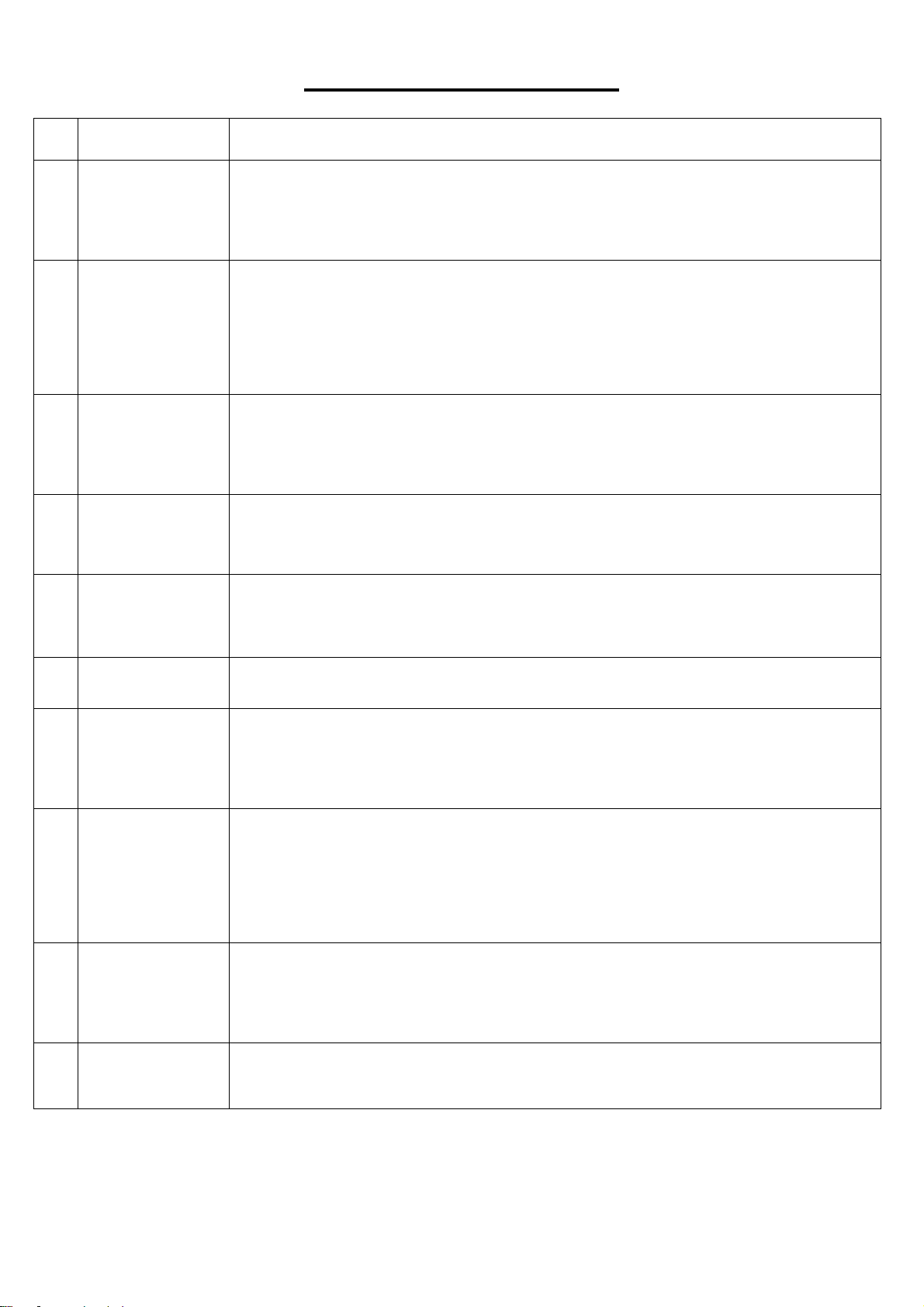
※ Error code display during measurement:
E-1--- user not hold pulse sensors correctly (Drawing 33)
E-4--- Body Fat% exceed setting range 5.0%~ 50% (Drawing 34)
Drawing 33 Drawing 34
KILOMETERS OR MILES
1. In stop mode, using three fingers, press MODE, START/STOP, RESET sequentially and hold at the same
time for a few seconds.
2. Press and hold MODE, then press RESET and continue pressing both keys for a few seconds until the
display changes. F01 will display in DISTANCE window, 78 will display in CALORIES window. Do not set
any data. (Drawing 34).
3. Press MODE to select F02, use + or - to change from kilometers or miles. 0 is for KM (Drawing 35), 1 is
for ML (Drawing 36).
4. Press RESET to restart the meter.
Drawing 34 Drawing 35 Drawing 36
MP3 Function:
You can connect mobile or music player to meter with audio cable (included) for MP3 function.
(Reminder: meter only has the function of power amplifier but not read memory card.) Music is controlled
from the mobile or music device.
USB power charger: The meter can provide USB charger for tablet or smart phone. Plug the data cable into
USB port for charging (cable not included).
Note:
After 4 minutes without pedaling or pulse input, meter will enter into power saving mode. Press any key to
turn the meter on.
19
TROUBLESHOOTING
NO.
POTENTIAL
REASONS
SOLUTIONS
1
LCD no display.
1. Check the meter together with the stage’s 9 or 12 PIN connect cable, to see if
the meter has bad contact or get loose with the stage’s 9 or 12 PIN connect
cable.
2. Check if the DC JACK 3PIN connect cable are loose or not.
2
No alteration of
resistance
1. When the LOAD/LEVEL is up or down, see if the motor is running or not.
2. Check the meter together with the stage’s 9 or 12 PIN connect cable, to see if
the meter has bad contact with or has loosened from the stage’s 9 or 12 PIN
connect cable.
3. See if the motor is running or not after plug in the adaptor again and turn on the
meter.
3
No hand pulse
figure display
1. Make sure the user holds onto the handgrip sensor. Please hold two hands
together during training period.
2. Check the signal cable which in the pulse sensor to see if it is loose or not.
3. To see the meter whether in the low-speed (energy saving mode) or not.
4
No display of
Built-in figure
1. Check the battery is dead or not, please change the battery and test it again.
2. See the meter whether in the low-speed (energy saving mode) or not.
5
LCD display E-1
1. E-1 indicates the meter does not receive the body fat figure. Make sure the user
holds onto the handgrip sensor. Please do hold two hands together during
training period.
6
LCD display E-4
1. E-4 is indicate the user’s age, height, weight figure exceeds the setting range when
user setting their information.
7
LCD display E-2
1. Check the meter together with the stage’s 9 or 12 PIN connect cable, to see if
the meter has bad contact with or has loosened from the stage’s 9 or 12 PIN
connect cable.
2. Check if the motor distance exceeds the setting range or not.
8
LCD display E-3
1. Check whether the motor 2 PIN cable is connected or not.
2. Check whether the switch cabinet is fixed too far away.
3. Check if motor cable is broken or connected well to meter.
4. Change the switch cabinet.
5. Change another meter to test. If it displays correctly, then it is meter problem. If
it still displays E-3, contact customer service.
9
No display of
SPEED figure
1. Check the meter together with the stage’s 9 or 12 PIN connect cable, to see if
the meter has bad contact with or has loosened from the stage’s 9 or 12 PIN
connect cable.
2. Check the speed sensor cable, to see if it is bad contact or getting loose.
10
Fail to respond
the RECOVERY
function.
1. Check if the meter is in the STOP condition or not.
2. Check the pulse function to see if it can display the pulse figure or not.
Version 1.1

20