
IMPORTANT SAFETY INFORMATION
We thank you for choosing our product. To ensure your safety and health, please use this
equipment correctly. It is important to read this entire manual before assembling and using the
equipment. Safe and effective use can only be achieved if the equipment is assembled,
maintained and used properly. It is your responsibility to ensure that all users of the equipment
are informed of all warnings and precautions.
1. Before starting any exercise program, you should consult your physician to determine if you
have any medical or physical conditions that could put your health and safety at risk, or
prevent you from using the equipment properly. Your physician’s advice is essential if you are
taking medication that affects your heart rate, blood pressure or cholesterol level.
2. Be aware of your body’s signals. Incorrect or excessive exercise can damage your health.
Stop exercising if you experience any of the following symptoms: pain, tightness in your chest,
irregular heartbeat, shortness of breath, lightheadedness, dizziness or nauseous feeling. If
you do experience any of these conditions, you should consult your physician before
continuing with your exercise program.
3. Keep children and pets away from the equipment. The equipment is designed for adult use
only.
4. Use the equipment on a solid, flat level surface with a protective cover for your floor or carpet.
To ensure safety, the equipment should have at least 4 feet (1.2 M) of free space all around it.
5. Ensure that all nuts and bolts are securely tightened before using the equipment. The safety of
the equipment can only be maintained if it is regularly examined for damage and/or wear and
tear.
6. Always use the equipment as indicated. If you find any defective components while
assembling or checking the equipment, or if you hear any unusual noises coming from the
equipment during exercise, discontinue use of the equipment immediately and do not use until
the problem has been rectified.
7. Wear suitable clothing while using the equipment. Avoid wearing loose clothing that may
become entangled in the equipment.
8. Do not place fingers or objects into the moving parts of the equipment.
9. The maximum weight capacity of this unit is 300 pounds (136 KG).
10. The equipment is not suitable for therapeutic use.
11. To avoid bodily injury and/ or damage to the product or property, proper lifting and moving are
required.
12. Your product is intended for use in cool and dry conditions. You should avoid storage in
extreme cold, hot or damp areas as this may lead to corrosion and other related problems.
13. This equipment is designed for indoor and home use only; it is not intended for commercial
use.
1

ε
豆豆記 間
會豈言語
呵

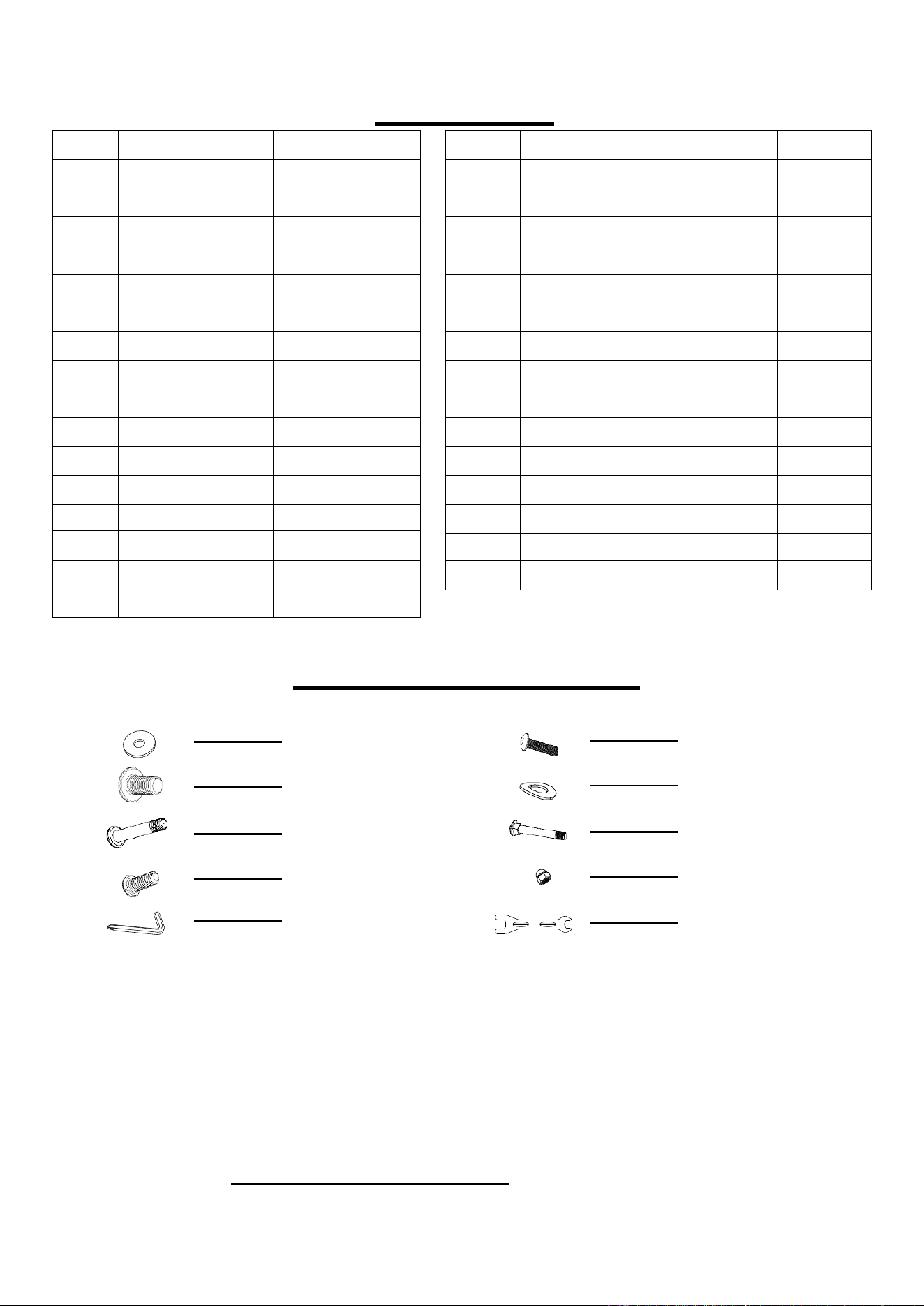
PARTS LIST
3
No.
Description
Spec.
Qty.
33
Cap
1
34
Tube
1
35
Bushing
1
36
Label
1
37
Tube
1
38
Sleeve
2
39
Sensor
1
40
Bolt
M8
4
41
Plastic Washer
1
42
Bolt
M4
8
43
Rod
1
44
Bushing
6
45
Bolt
M8
1
46
Cover-R
1
47
Front Cover
1
48
Cover-L
1
49
Seat Connect Tube
1
50
Wire
1
51
Cap Nut
4
52
Rear End Cap
2
53
Main Frame
1
54
Spacer
1
55
Cap
2
56
Nut
M10
2
57L/R
Crank-L&R
2
58L/R
Pedal-L&R
2
59
Bolt
M6
11
60
Mounting Plate
2
61
Spacer
6
62
Bearing
6003
2
63
Bearing Seat
2
64
Belt Wheel
1
No.
Description
Spec.
Qty.
1
Meter
1
2
Handle Bar
1
3
Sponge
2
4
Bolt
M5
2
5
Bolt
M8
2
6
Bolt
M4
2
7
Pulse
2
8
Washer
M8
6
9
Tension
1
10
Washer
1
11
Bolt
M5
1
12
Seat
1
13
Seat Tube
1
14
Bushing
1
15
Washer
7
16
Bolt
M8
5
17
Back Pad
1
18
Cap
1
19
Bolt
M8
3
20
Bolt
M5
2
21
Cup Holder
1
22
Back Pad Tube
1
23
Bolt
M8
2
24
Washer
2
25
Nut
M8
4
26
Sponge
2
27
Seat Handle Bar
1
28
Cap
2
29
Handlebar Bracket
1
30
Bolt
M8
2
31
Cap
2
32
Pop-Pin Knob
2
PARTS LIST
4
HARDWARE PACKAGE
#15 3pcs
#16 3pcs
#19
2pcs
# 20
2pcs
# 5 2pcs
# 8 6pcs
# 40
4pcs
# 51
4pcs
A
B
Ordering Replacement Parts (U.S. and Canadian Customers only)
Please provide the following information in order for us to accurately identify the part(s) needed:
✓ The model number (found on cover of manual)
✓ The product name (found on cover of manual)
✓ The part number found on the “EXPLODED DIAGRAM” and “PARTS LIST” (found near the
front of the manual)
Please contact us at support@sunnyhealthfitness.com or 1- 877 - 90SUNNY (877-907-8669).
No.
Description
Spec.
Qty.
81
Bearing
6000
2
82
Belt Wheel
1
83
Belt
230J3
1
84
Axle
1
85
Magnet Spacing
1
86
Bolt
M4
1
87
Spring
1
88
Iron Sheet
1
89
Magnet
4
90
Front Tube
1
91
Rear Tube
1
92
Front End Cap
2
93
Washer
2
A
Wrench
1
B
Spanner
1
No.
Description
Spec.
Qty.
65
Middle Axle
1
66
Wheel
1
67
Washer
1
68
Nut
M10
1
69
Washer
2
70
Axle
1
71
Washer
4
72
Plastic Idler
1
73
Belt
240J3
1
74
Spacer
2
75
Washer
1
76
Nut
M10
3
77
Bolt
2
78
Iron Sheet
2
79
Nut
M6
2
80
Bolt
2
ASSEMBLY INSTRUCTIONS
We value your experience using Sunny Health and Fitness products. For assistance with parts or
troubleshooting, please contact us at support@sunnyhealthfitness.com or 1-877-90SUNNY (877-907-
8669).
5
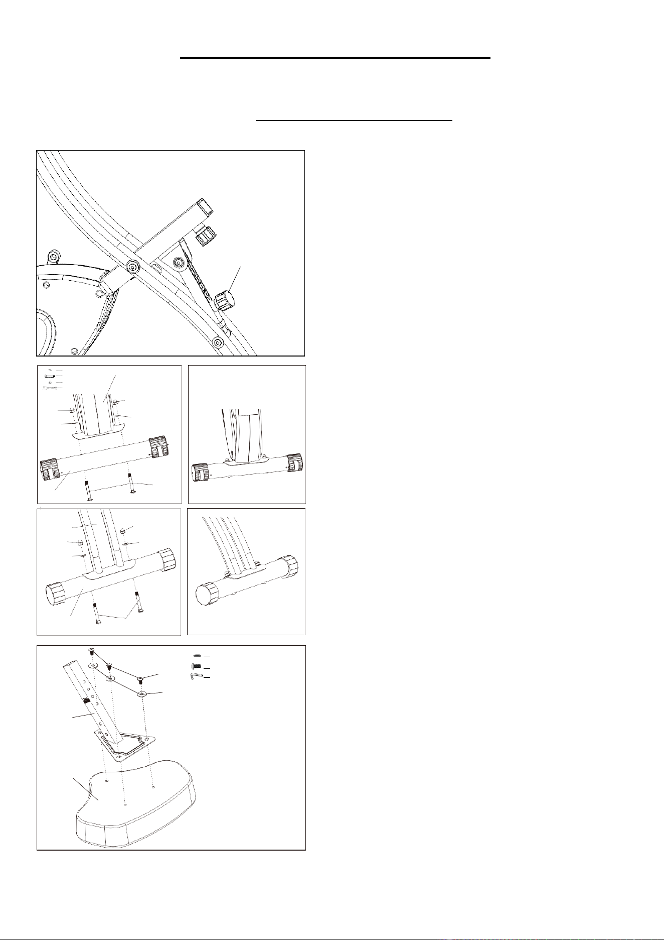
STEP 1:
Slightly loosen the Pop-Pin Knob (No. 32) and pull
outward to adjust your desired recline angle (1-3
setting).
STEP 2:
Install Front Tube (No. 90) and Rear Tube (No. 91)
onto Main Frame (No. 53) (please see image to
ensure the both tubes are installed on correct
position). Insert Bolts (No. 40) through hole in Front
Tube (No. 90) and Rear Tube (No. 91) and place
the Washers (No. 8) onto Bolts (No. 40). Then,
tighten Cap Nuts (No.51) onto Bolts (No. 40) with
Spanner (B).
STEP 3:
Attach Seat (No. 12) to the Seat Support Tube
(No. 13)
using 3 Washers (No. 15) and 3 Bolts
(No. 16). Tighten and secure with Wrench (A).
32
16
15
# 15 3pcs
# 16 M8 3pcs
A
13
12
#8 M8 4pcs
#40 M8 4pcs
#51 4pcs
B
53
51
51
8
8
40
90
53
51
8
51
8
91
40
ASSEMBLY INSTRUCTIONS
We value your experience using Sunny Health and Fitness products. For assistance with parts or
troubleshooting, please contact us at support@sunnyhealthfitness.com or 1-877-90SUNNY (877-907-
8669).
6
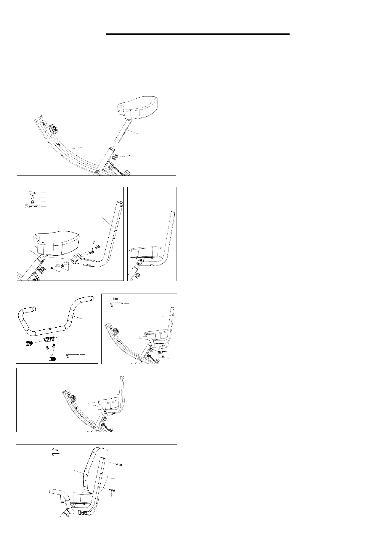
STEP 4:
Loosen Pop-Pin Knob (No. 32), and insert the Seat
Support Tube (No. 13) into Main Frame (No. 53).
Set Seat Support Tube (No. 13) at desired height
and make sure the Pop-Pin Knob (No. 32) goes into
one of the holes. Tighten Pop-Pin Knob (No. 32) to
secure.
STEP 5:
Remove preassembled Bolts (No. 23), Nuts (No.
25), and Washers (No. 24) from the Back Pad Tube
(No. 22). Align Back Pad Tube (No. 22) with hole in
the Seat Support Tube (No. 13), and insert Bolts
(No. 23) through hole in Back Pad Tube (No. 22).
Place Washers (No. 24) onto the Bolts (No. 23), and
screw on the Nuts (No. 25) and tighten with Spanner
(B).
STEP 6:
Remove the Handlebar Bracket (No. 29)
and
Bolts
(No. 30) from
the Back Pad Tube (No. 22)
.
Align
the Seat Handle Bar (No. 27) with holes on the
bottom of the Back Pad Tube (No. 22), and
place
Bolts (No. 30) into holes and tighten with Wrench (A).
STEP 7:
Align Back Pad (No. 17) against Back Pad Tube (No
.
22), and insert Bolts (No. 19) into holes. Then, tighten
with Wrench (A).
13
53
32
#23 M8 2pcs
#24 2pcs
#25 M8 2pcs
B
22
23
13
25
24
#19 M8 2pcs
A
19
17
22
19
#30 M8 2pcs
A
22
27
29
30
27
A
ASSEMBLY INSTRUCTIONS
We value your experience using Sunny Health and Fitness products. For assistance with parts or
troubleshooting, please contact us at support@sunnyhealthfitness.com or 1-877-90SUNNY (877-907-
8669).
7
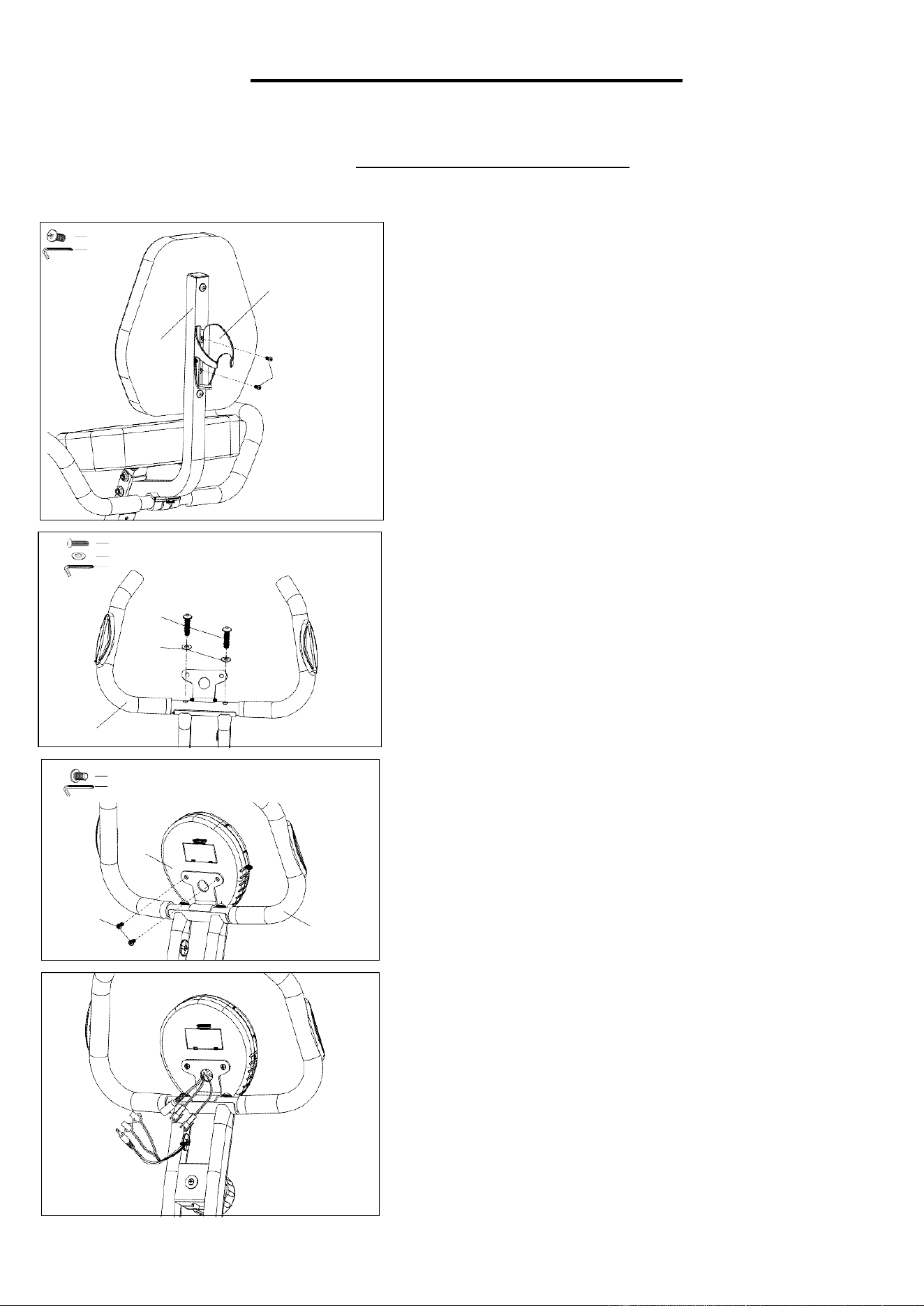
STEP 8:
Align Cup Holder (No. 21) against Back Pad Tube (No. 22),
and insert Bolts (No. 20)
into holes. Then, tighten with
Wrench
(A).
STEP 9:
Assemble the Handle Bar (No. 2) into slots on the top of
the Main Frame (No. 53).
Place
Bolts (No. 5)
and
Washers
(No. 8) into holes and
(A).
STEP 10:
tighten Bolts (No. 5)
with Wrench
Remove preassembled Bolts (No. 4) from the back of the
Meter (No. 1), and place Meter (No. 1) onto the Handle Bar
(No. 2). Then, tighten with Wrench (A).
STEP 11:
Connect all wires from Main Frame (No. 53) to Meter
(No. 1). The 2 round bigger ones must be wired to each
other. The other square wires can be interchangeably
connected to each other.
#20 M5 2pcs
A
21
22
20
#5 M8 2pcs
#8 2pcs
A
5
8
2
#4 M5 2pcs
A
1
4
2
ASSEMBLY INSTRUCTIONS
We value your experience using Sunny Health and Fitness products. For assistance with parts or
troubleshooting, please contact us at support@sunnyhealthfitness.com or 1-877-90SUNNY (877-907-
8669).
8
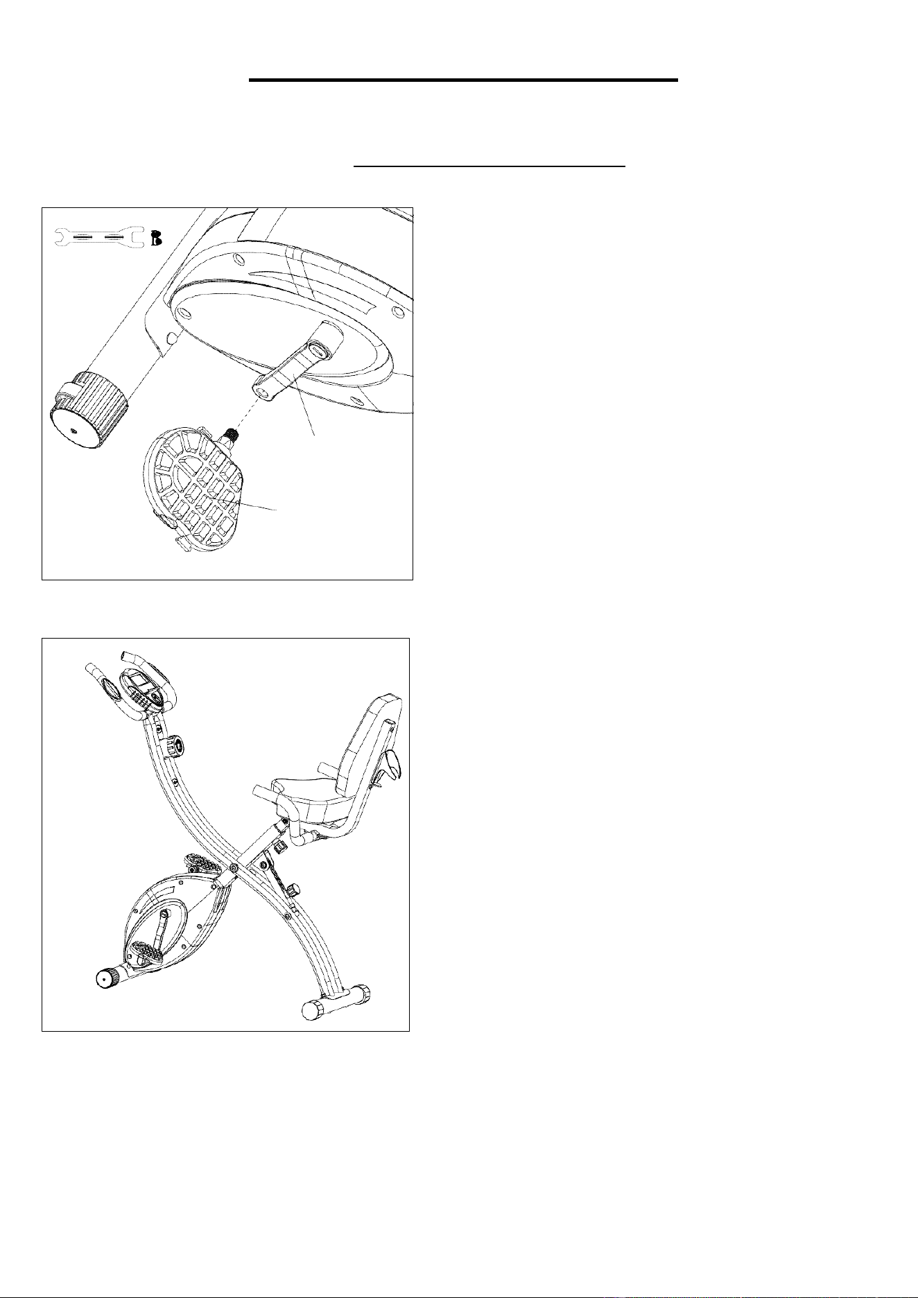
STEP 12:
Attach the Left and Right Pedals (No. 58L/R) to the
Left and Right Cranks (No. 57L/R).
Left Pedal: align the Left Pedal (No. 58L) with the
Left Crank Arm (No. 57L) at 90 degrees. Insert pedal
into crankarm, then turn pedal counter-clockwise as
tightly as you can by hand. Tighten and secure with
Spanner (B).
Right Pedal: align the Right Pedal (No. 58R) with the
Right Crank Arm (No. 57R) at 90 degrees. Insert
pedal into crank arm, then turn pedal clockwise as
tightly as you can by hand.
Tighten and secure with Spanner (B).
The assembly is complete!
57-L
58-L

EXERCISE COMPUTER
FUNCTION KEY:
9
MODE: To select functions. Press and hold for a few seconds to set values to 0.
FUNCTIONS AND SPECIFICATIONS:
SCAN -- Press “MODE” button until “SCAN” appears, monitor will rotate through all
6 functions: Time, speed, distance, calorie, ODO and pulse. Each function will display
for 5 seconds.
TIME -- Count the total time from exercise start to finish.
SPEED -- Display current training speed.
DISTANCE -- Count mileages from exercise start to finish.
CALORIES -- Count the total calories from exercise start to finish.
ODOMETER -- The total distance since batteries were installed into the meter.
PULSE RATE -- Press MODE button until “PULSE” appears. Before measuring your pulse rate, please place
the palms of your hands on both the contact pads. After 6~7 seconds, the monitor will show your current
heartbeat rate in beats per minute (BPM) on the LCD. Remark: During the process of pulse measurement,
because of the contact jamming, the measurement value may be higher than the virtual pulse rate during the first
2~3 seconds, then will return to normal level. The measurement value cannot be regardedas the basis of medical
treatment.
OPERATION PROCEDURES:
1. AUTO ON/OFF:
The meter will turn on when you press any button or start pedaling. After 4
minutes without any signal, the meter will turn off automatically.
2.
BATTERY / TROUBLESHOOT: The display console uses two AA batteries, which are included. If the
display appears improper or becomes difficult to read, please try installing new batteries before contacting
our customer service.

10
BATTERY INSTALLATION & REPLACEMENT
BATTERY INSTALLATION:
1. Take out 2 AA batteries from meter box.
2. Press the buckle of battery cover on the Meter (No. 1), then remove battery cover.
3. Install 2 AA batteries into the battery case on the back of the Meter (No. 1). Pay attention to the
battery + and – poles before installing.
4. Press the buckle of battery cover, then put the battery cover back to the back of the Meter (No.
1).
5. The installation is complete!
BATTERY REPLACEMENT:
1. Press the buckle of battery cover on the back of the Meter (No. 1), then remove battery cover.
2. Remove the 2 old AA batteries in the battery case and install 2 new AA batteries into the battery
case on the back of the Meter (No. 1). Pay attention to the battery + and – poles before
installing.
3. Press the buckle of battery cover, then put the battery cover back to the back of the Meter (No.
1).
4. The replacement is complete!

11
OPERATING INSTRUCTIONS
1. Please read all instructions before assembling the equipment. During assembly and use, please make sure to
follow all instructions carefully as any improper techniques of use or assembly may result in injury or damage to
the equipment.
2. The suggested exercise regimen for optimal results is 10-15 minutes per day, at least three times a week.
3. Before beginning exercise, always inspect the equipment to ensure that all moving parts, as well as hardware,
are secured properly and are in good condition.
4. To adjust the level of tension, turn the Tension Knob to the left or right and align the arrow to the preferred
tension level as shown below. This machine contains 10 different levels of tension, with Level 1 being the
lowest and Level 10 being the highest. Turn the Tension Knob to the left to decrease the level of tension, turn
the Tension Knob to the right to increase the level of tension.
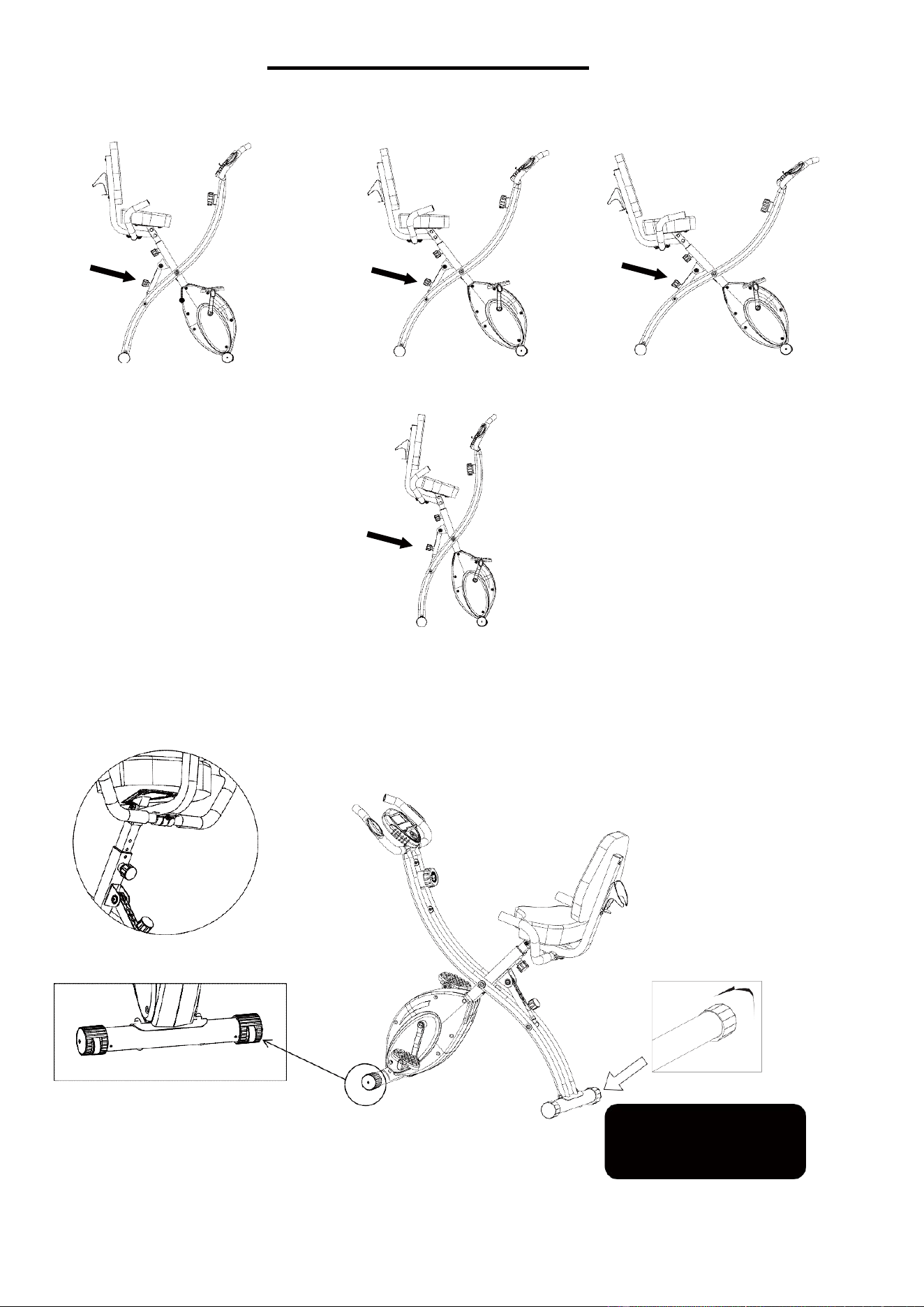
ADJUSTMENT GUIDE
THREE LEVEL AND FOLDING ADJUSTMENT: Turn and pull the knob to adjust the level.
LEVEL 2
LEVEL 3
FOLDING
SEAT TUBE ADJUSTMENT: Turn and pull the knob to adjust the seat tube.
12
Version 1.6
TRANSPORT WHEEL
Please adjust the end caps if
there is a slight imbalance
problem caused by uneven ground.
LEVEL 1