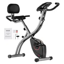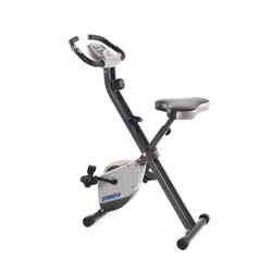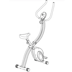
XRB 100
F o l d i n g E x e r c i s e B i k e
OWNER’S MANUAL
* This item is for consumer use only and it is not meant for commercial use.
General Information
XRB 100 X-Bike Page 1
Warranty
Body Flex Sports warrants your product for
a period of 1 year for the frame and 90 days
on all parts if the item is used for the intended
purpose, properly maintained and not used
commercially. Any alterations or incorrect
assembly of the product will void this warranty.
Proof of purchase must be presented for any
warranty validation (no exceptions). This
warranty applies to the original purchaser only
and is not transferable.
This warranty does not cover abuse or defects
caused during use, storage or assembly.
During the warranty period, Body Flex Sports
reserves the right to:
a). provide replacement parts to the
purchaser in an effort to repair the item.
b). repair the product returned to our
warehouse (at the purchaser’s cost).
c). replace the product if neither of the two
previously mentioned actions effect repair.
This warranty does not cover normal wear and
tear on upholstery.
Questions
If you have any questions concerning the
assembly of your item or if any parts are
missing, please DO NOT RETURN THE
ITEM TO THE STORE OR CONTACT THE
RETAILER. Our dedicated customer service
staff can help you with any questions you may
have regarding the assembly of this unit and
can also mail you replacement parts.
Customer Support
Customer Support is open 9:00 a.m. to 5:00
p.m. (Pacic Time) Monday through Friday.
Please contact us by any of the following
means.
Body Flex Sports, Inc.
21717 Ferrero Parkway, Walnut, CA 91789
Telephone: (888) 266 - 6789
Fax: (909) 598 - 6707
Email: info@bodyexsports.com
Safety
Before you undertake any exercise program,
please be sure to consult with your doctor.
Frequent strenuous exercise should be
approved by your doctor and proper use
of your product is essential. Please read
this manual carefully before commencing
the assembly of your product or starting to
exercise.
• Please keep all children away from this item
when in use. Do not allow children to climb or
play on them when they are not in use.
• Supervise teenagers while they use this unit.
• For your own safety, always ensure that there
is at least 3 feet of free space in all directions
around your product while you are exercising.
• Regularly check to see that all nuts, bolts and
ttings are securely tightened. Periodically
check all moving parts for obvious signs of
wear or damage.
• Clean only with a damp cloth, do not use
solvent cleaners. If you are in any doubt, do
not use your product; contact CUSTOMER
SUPPORT.
• Before use, always ensure that your product
is positioned on a solid, at surface. If
necessary, use a rubber mat underneath to
reduce the possibility of slipping.
• Always wear appropriate clothing and
footwear such as training shoes when
exercising. Do not wear loose clothing that
could become caught in moving parts during
exercise.
• Do not use this unit if it is not functioning
properly or if it is not fully assembled.
• Do not use this unit for commercial purposes.
Storage and Use
Your product is intended for use in clean
dry conditions. You should avoid storage in
excessively cold or damp places as this may
lead to corrosion and other related problems.
Weight Limit
The maximum resting weight capacity of this
unit is 250 pounds.
XRB 100 X-Bike Page 2
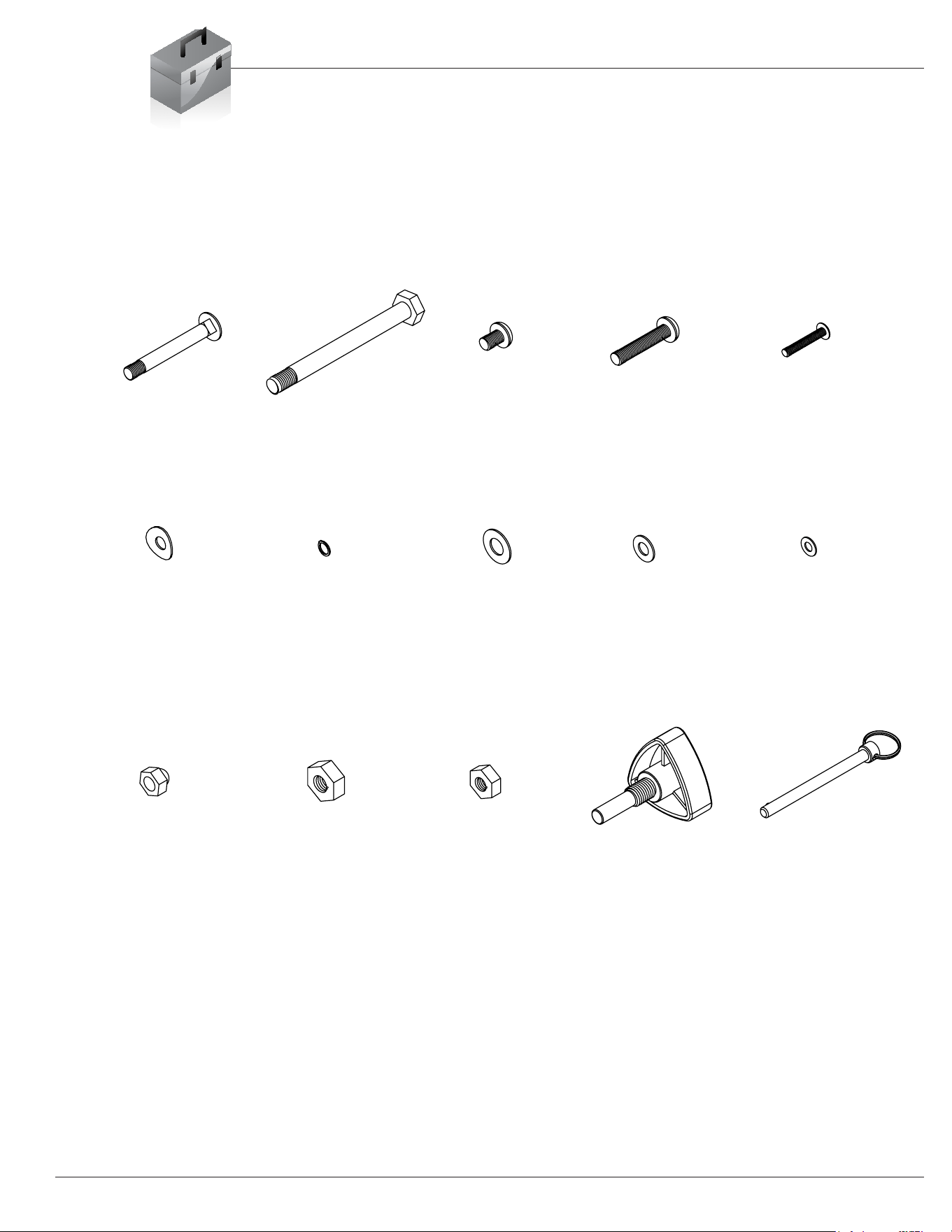
Hardware List
The following hardware is used to assemble your unit. Please take a moment to
familiarize yourself with these items.
M8*65 mm
#13 CARRIAGE BOLT
#14 ARC-WASHER
for M8 SCREW
#16 NUT
for #13 BOLT
M8*15 mm
#24 SCREW
for M8 SCREW
#22 NYLON NUT
#19 WASHER
for M10 BOLT
M10*105 mm
for M10 BOLT
#17 HEX BOLT
#20 NYLON NUT
#15 SPRING WASHER
for M8 SCREW
M8*40 mm
#25 SCREW
#23 WASHER
for M8 SCREW
#21 KNOB
M10*45 mm
M5*30 mm
#31 SCREW
#18 POP-PIN
#32 WASHER
for M5 SCREW
PLEASE NOTE: some of these parts may have already been pre-assembled on your unit.
XRB 100 X-Bike Page 3
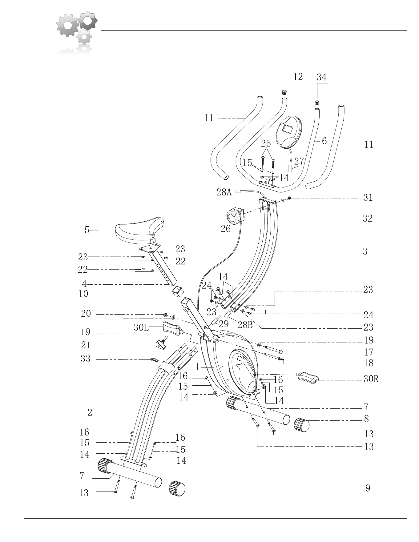
Parts Listing
Part # Description
1. ..................... Main frame
2. ..................... Lower frame
3 ...................... Upper frame
4 ...................... Seat post
5 ...................... Seat
6 ...................... Handle bar
7 ...................... Stabilizer
8 ...................... End cap
9 ...................... Adjustable end cap
10 .................... Seat post sleeve
11 .................... Handle bar grips
12 .................... Computer console
13 .................... Carriage bolt (M8*65mm)
14 .................... Curved washer (for M8 screw)
15 .................... Spring washer (for M8 screw)
16 .................... Nut (for #13 bolt)
17 .................... Hex bolt (M10*105mm)
18 .................... Pop pin
Part # Description
19 .................... Washer (for M10 bolt)
20 .................... Nylon nut (for M10 bolt)
21 .................... Knob
22. ................... Nylon nut (for M8 screw)
23 .................... Washer (for M8 screw)
24 .................... Screw (M8*15mm)
25 .................... Screw (M8*40mm)
26 .................... Tension controller
27 .................... Console wire
28A.................. Upper console wire A
28B ................. Upper console wire B
29 .................... Main frame console wire
30L .................. Left Pedal
30R ................. Right Pedal
31. ................... Screw (M5*30mm)
32 .................... Washer (for M5 screw)
33 .................... Bumper
34 .................... End cap
The following parts list describes all of the parts illustrated on the
exploded diagram on the following page. Please note, most of
these parts are already pre-assembled on your unit.
XRB 100 X-Bike Page 4
Exploded Diagram
9
9
XRB 100 X-Bike
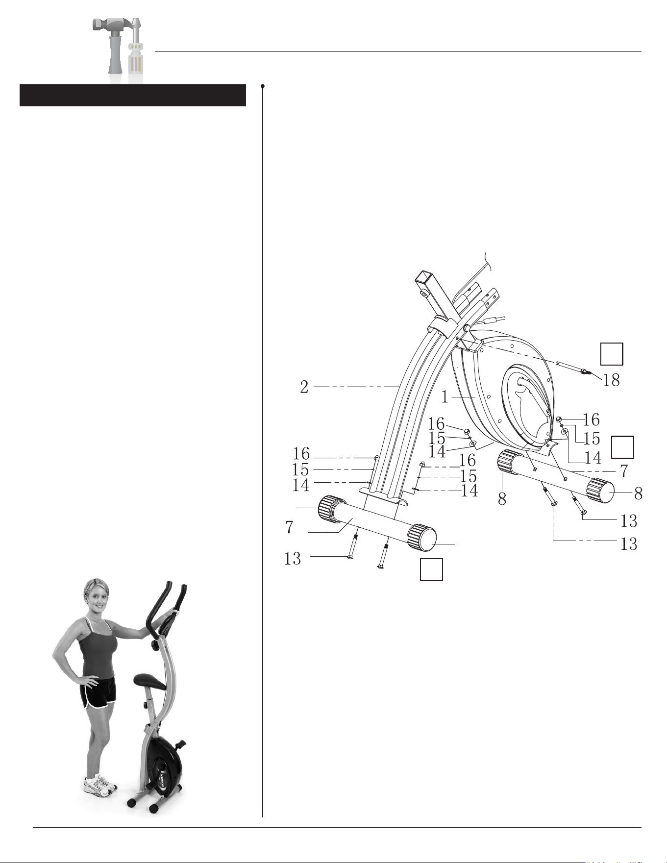
Assembly Instructions
A. Attach the Stabilizer (#7), which has
the Adjustable end caps (#9) attached to
it, to the Lower frame (#2). Secure it with
two Carriage bolts [M8*65mm] (#13), two
Curved washers [for M8 screw] (#14)
followed by two Spring washers [for M8
screw] (#15) and secure with two Nuts [for
#13 bolt] (#16). Note1: carriage bolts have a
dome shaped head. Note 2: The Adjustable
end caps (#9) rotate to compensate for
uneven surfaces and also allow the unit to roll
when you are storing it.
B. Attach the other Stabilizer (#7) to the Main
frame (#1). Secure it with two Carriage bolts
[M8*65mm] (#13), two Curved washers [for
M8 screw] (#14) followed by two Spring
washers [for M8 screw] (#15) and secure
with two Nuts [for #13 bolt] (#16).
C. Insert Pop pin (#18) into the hole located
on the Lower frame (#2) until it passes
through the Main frame (#1) and clicks into
place. This pin MUST remain inserted while
the unit is in use OR simply unfolded. After
you complete the assembly, you will be able
to fold the unit for storage. Please follow the
instructions below for more details:
X-Bike FOLDING INSTRUCTIONS:
To fold your unit simply remove the Pop pin
(#18), fold the unit and then re-insert Pop pin
(#18) ensuring the pin clicks into place.
A s s e m b l y S t e p 1
Page 5
A
B
C
NOTE: Prior to beginning assembly, it is necessary to remove
the Pop pin (#18) from the Main frame (#1) in order to open
the frame as illustrated below.
XRB 100 X-Bike
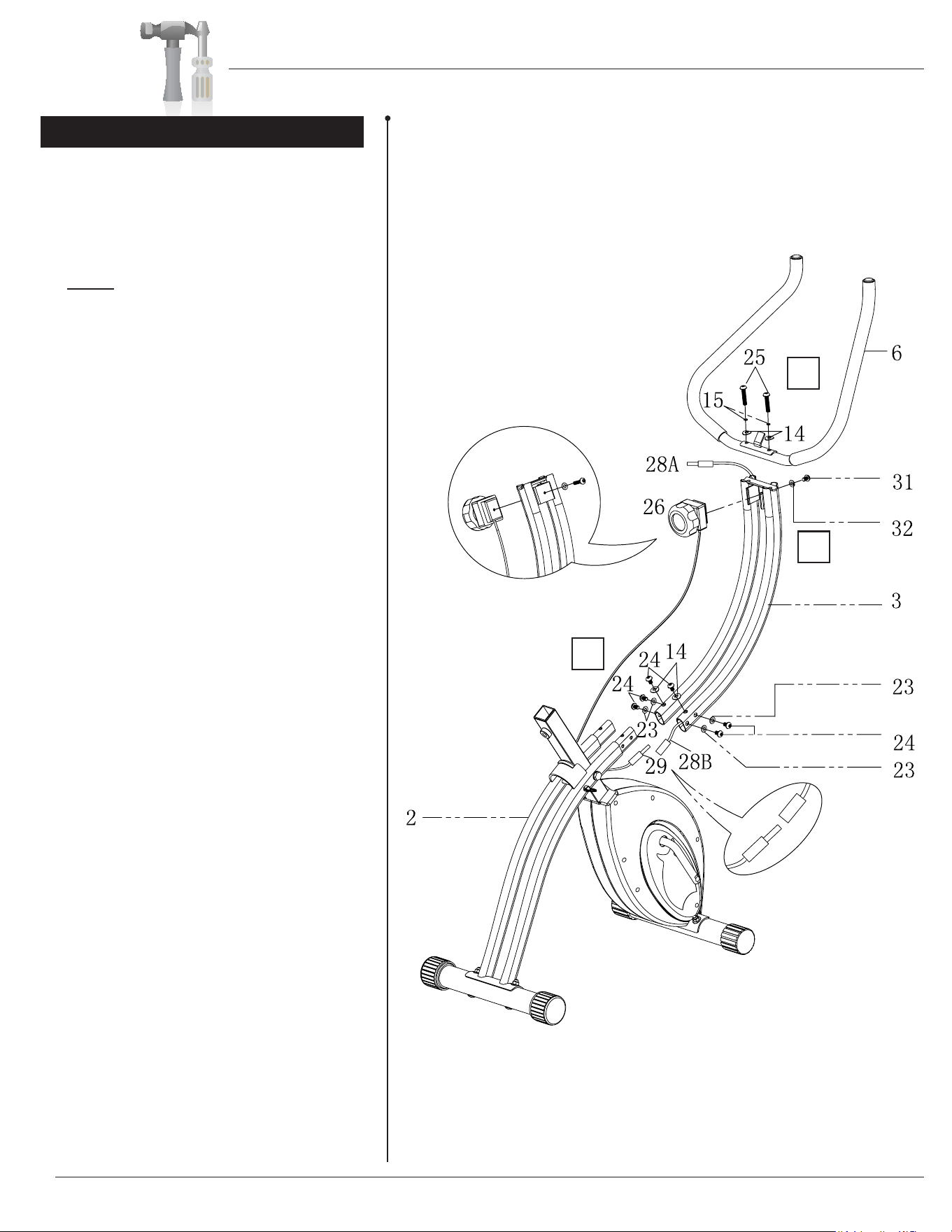
Assembly Instructions
Page 6
A. Connect the Main frame console wire
(#29) to the Upper frame console wire
(#28B). Slide the Upper frame (#3) onto
the Lower frame (#2). Slide four Screws
[M8*15] (#24) through four Washers [for
M8 screw] (#23) and screw them through
the SIDES of the Upper frame (#3) loosely
(don’t tighten yet). Slide two Screws [M8*15]
(#24) through two Curved washers [for M8
screw] (#14) and screw them through the
TOP of the Upper frame (#3) rmly. Tighten
all screws.
B. Slide the Tension controller (#26) (from
the underneath) into the bracket located on
the Upper frame (#3) and secure it using one
Washer [for M5 screw] (#32) and one Screw
[M5*30mm] (#31).
C. Attach the Handle bar (#6) to the Upper
frame (#3) using a total of two Screws
[M8*40mm] (#25) followed by two Spring
washers [for M8 screw] (#15) and two
Curved washers [for M8 screw] (#14).
A s s e m b l y S t e p 2
A
B
C
XRB 100 X-Bike
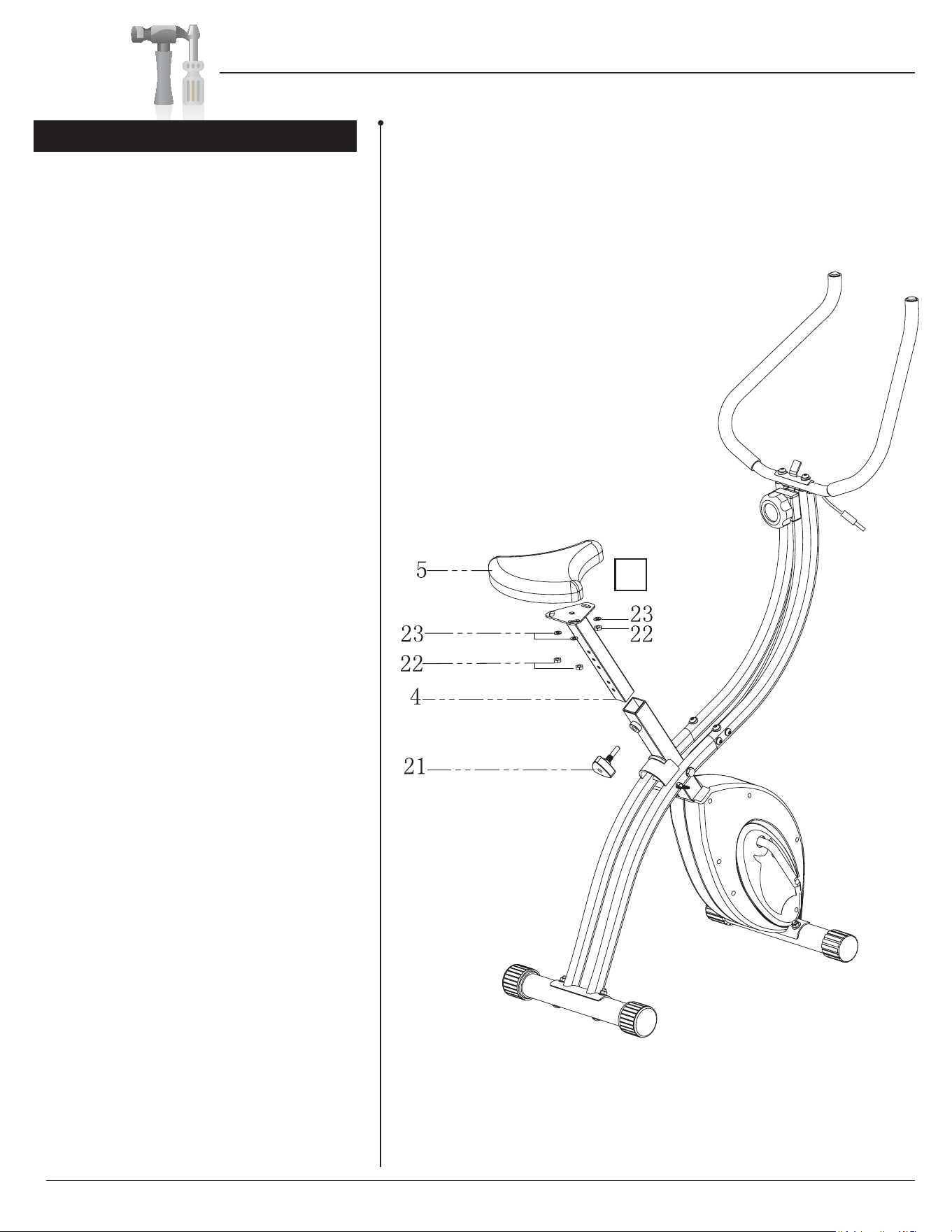
Assembly Instructions
Page 7
A. Attach the Seat (#5) to the Seat post
(#4) using a total of three Washers [for M8
screw] (23) and three Nylon nuts [for M8
screw] (#22). Slide the Seat post (#4) into
the Seat post sleeve (#10). Screw Knob
(#21) through the Main frame (#1) and then
into the hole located on the Seat post (#4)
that best accommodates your height and
screw snugly.
A s s e m b l y S t e p 3
A
XRB 100 X-Bike
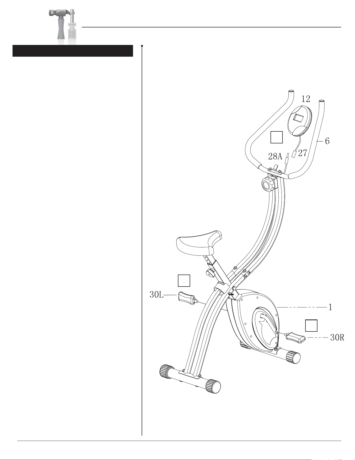
Assembly Instructions
Page 8
A. Connect the Console wire (#27) to the
Upper console wire (#28A) and then slide
the Computer console (#12) onto the bracket
located on the Handle bar (#6) until it clicks.
B. Screw Pedal (#30L) onto the crank shaft
COUNTER-CLOCK-WISE. You must use a
wrench to tighten it securely.
C. Screw Pedal (#30R) onto the crank shaft
CLOCK-WISE. You must use a wrench to
tighten them securely.
A s s e m b l y S t e p 4
A
C
B
XRB 100 X-Bike
Safety Instructions / Computer Operation
Page 9
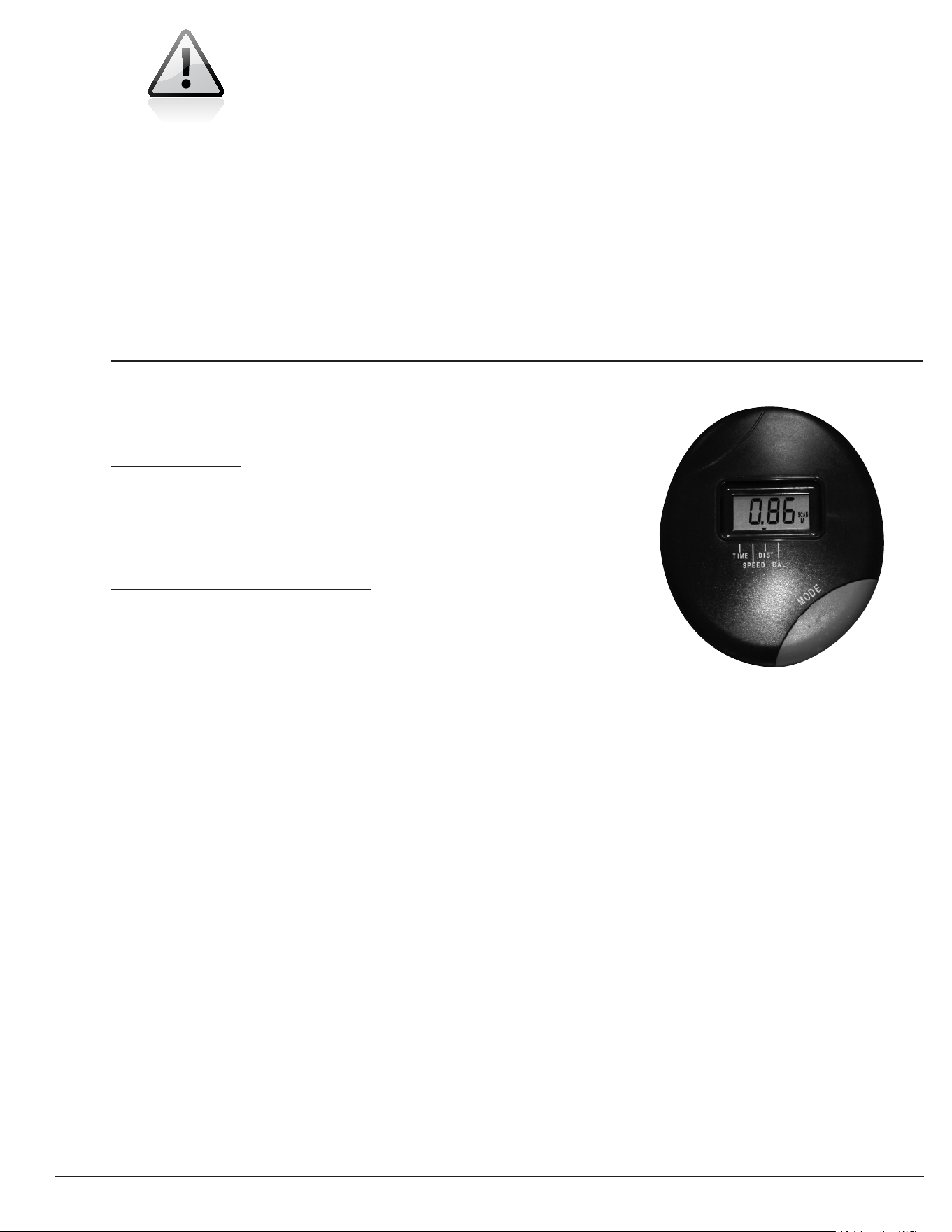
EXERCISE COMPUTER INSTRUCTIONS
MODE BUTTON:
MODE/RESET - Push MODE to select different functions.
- Push MODE and hold for three seconds
to reset time, distance and calories.
FUNCTIONS AND OPERATIONS:
1. SCAN: Press MODE button until SCAN appears in
small letters to the right of the digits. The
display will scan through these functions:
time, speed, distance and calorie. Each
function will show for four seconds before
changing to the next one.
2. TIME: Counts the total exercise time
3. SPEED: Displays current speed.
4. DIST: Measures the total distance in miles
5. CALORIES: Estimates total calories burned
6. AUTO ON/OFF & AUTO START/STOP:
The computer console automatically turns
on once you start exercising and shuts
off if there is no activity for eight minutes.
You can also manually turn the computer
console on my pressing the MODE button.
If the unit does not turn on, replace the
batteries.
Console uses two AA batteries. Remove the batteries if you
plan to store the unit for more than one month.
SAFETY INSTRUCTIONS
• Make sure all bolts are tightened.
• Check for loose parts and components
• Check to see if there are any tears or bends in the welding or metal.
• Be sure that all adjustment and locking devices and safety devices
are properly engaged prior to use!
Thanks for choosing
"ODY&LEX3PORTS)NC
&ERRERO0ARKWAY
7ALNUT#!
0HONE
&AX
%MAILINFO BODYFLEXSPORTSCOM
XRB 100
Store Location:

Body Flex Sports, Inc. • 21717 Ferrero Parkway, Walnut, CA 91789 • Telephone: (888) 266 - 6789 • Email: info@bodyexsports.com