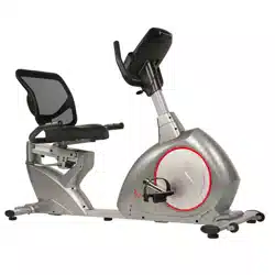
PINK FOLDING RECUMBENT BIKE
SF-RB1117
USER MANUAL
IMPORTANT! Please retain owner’s manual for maintenance and adjustment instructions. Your
satisfaction is very important to us, PLEASE DO NOT RETURN UNTIL YOU HAVE CONTACTED
US: [email protected] or 1- 877 - 90SUNNY (877-907-8669).

1
IMPORTANT SAFETY INFORMATION
We thank you for choosing our product. To ensure your safety and health, please use this equipment
correctly. It is important to read this entire manual before assembling and using the equipment. Safe
and effective use can only be achieved if the equipment is assembled, maintained, and used properly.
It is your responsibility to ensure that all users of the equipment are informed of all warnings and
precautions.
1. Before starting any exercise program, you should consult your physician to determine if you have
any medical or physical conditions that could put your health and safety at risk or prevent you from
using the equipment properly. Your physician’s advice is essential if you are taking medication
that affects your heart rate, blood pressure, or cholesterol level.
2. Be aware of your body’s signals. Incorrect or excessive exercise can damage your health. Stop
exercising if you experience any of the following symptoms: pain, tightness in your chest, irregular
heartbeat, shortness of breath, lightheadedness, dizziness, or feelings of nausea. If you do
experience any of these conditions, you should consult your physician before continuing with your
exercise program.
3. Keep children and pets away from the equipment. The equipment is designed for adult use only.
4. Use the equipment on a solid, flat level surface with a protective cover for your floor or carpet. To
ensure safety, the equipment should have at least 2 feet (60 CM) of free space all around it.
5. Ensure that all nuts and bolts are securely tightened before using the equipment. The safety of the
equipment can only be maintained if it is regularly examined for damage and/or wear and tear.
6. Always use the equipment as indicated. If you find any defective components while assembling or
checking the equipment, or if you hear any unusual noises coming from the equipment during
exercise, discontinue use of the equipment immediately and do not use until the problem has
been rectified.
7. Wear suitable clothing while using the equipment. Avoid wearing loose clothing that may become
entangled in the equipment.
8. Do not place fingers or objects into the moving parts of the equipment.
9. The maximum weight capacity of this unit is 220 pounds (100 KG).
10. The equipment is not suitable for therapeutic use.
11. To avoid bodily injury and/or damage to the product or property, proper lifting and moving are
required.
12. Your product is intended for use in cool and dry conditions. You should avoid storage in extreme
cold, hot or damp areas as this may lead to corrosion and other related problems.
13. This equipment is designed for indoor and home use only; it is not intended for commercial use.
2
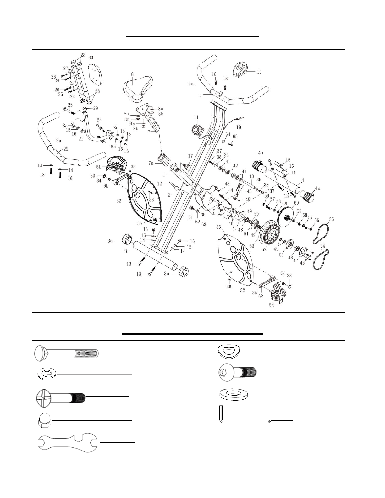
EXPLODED DIAGRAM
HARDWARE PACKAGE
#13 M8 x 65mm 4pcs
#14 Φ8x1.5 4pcs
#15 Φ8x1.5 4pcs
#18 M8 x 35mm 2pcs
#26 M6 x 40mm 4pcs
#27 Φ6.5 x 1.5 4pcs
#16 M8 4pcs
#20 S5 1pc
#31 S13, 14, 15 1pc

3
PARTS LIST
No.
Description
Spec.
Qty
1
Main Frame
20/40x1085mm
1
2
Rear Frame
oval
1
3
Rear Stabilizer
Φ50x395mm
1
3a
Adjustable End Cap
Φ50
2
4
Front Stabilizer
Φ50x285mm
1
4a
Front End Cap
Φ50
2
5L/R
Pedal
2
6L/R
Crank
5”
2
7
Seat Support
30/60x450mm
1
7a
Bushing
1
8
Seat
278*245mm
1
8a
Flat Washer
Φ8x1.5
6
8b
Nylon Nut
M8
3
9
Handlebar
Φ22x462mm
1
9a
Handlebar Foam
Φ22 x 310mm
2
10
Exercise Monitor
1
11
Tension Control Knob
1
12
Locking Pin
M10x105mm
1
13
Carriage Bolt
M8x65mm
4
14
Curved Washer
Φ8x1.5
6
15
Spring Washer
Φ8x1.5
7
16
Dome Nut
M8
7
17
Adjustment Knob
M16
1
18
Allen Bolt
M8x35mm
4
19
Sensor Wire
1
20
Allen Wrench
S5
1
21
Back Support Frame
30/30x258mm
1
22
Rear Handlebar
Φ22x462mm
1
23
Backrest Support
30/15x245mm
1
24
Carriage Bolt
M8x45mm
2
25
Allen Bolt
M8x75mm
1
26
Screw
M6x40mm
4
27
Flat Washer
Φ6.5 x 1.5
4
28
End Cap
30/15
4
29
Square End Cap
30/30
1
30
Backrest
193x255mm
1
No.
Description
Spec.
Qty
31
Spanner
S13, 14, 15
1
32
Chain Cover
2
33
Crank Guard Trim
2
34
Nut
M10
2
35
Self-tapping Screw
M4x20mm
4
36
Self-tapping Screw
M4x20mm
2
37
Allen Bolt
M8x20mm
2
38
Spring Washer
Φ8x1.5
2
39
Flat Washer
Φ8x2.0
2
40
Main Axle
Φ17x150mm
1
41
Outer Bushing
4
42
Inner Bushing
2
43
Screw
M5x15mm
1
44
Spring
Φ9
1
45
Magnetic Bracket Set
1
46
Screw
M6x15mm
7
47
Round Steel
2
48
Bearing
6003Z
2
49
Spring Washer
Φ17
5
50
Wave Washer
Φ17
1
51
Bearing Bush
2
52
Drive Wheel Set
150mm
1
53
Flywheel
180
1
54
Drive Belt
230
1
55
Drive Belt
220
1
56
Nut
M10
2
57
Screw
M6x4mm
2
58
Flat Washer
Φ10
2
59
Nut
M10
2
60
Lower Drive Wheel
150mm
1
61
Bearing
608Z
1
62
Flat Washer
Φ10
1
63
Nylon Nut
M10
1
64
Flat Washer
Φ6.5 x 1.5
1
65
Screw
M5x30mm
1
Ordering Replacement Parts (U.S. and Canadian Customers only)
Please provide the following information in order for us to accurately identify the part(s) needed:
The model number (found on cover of manual)
The product name (found on cover of manual)
The part number found on the “EXPLODED DIAGRAM” and “PARTS LIST” (found near the
front of the manual)
Please contact us at [email protected] or 1- 877 - 90SUNNY (877-907-8669).
4
ASSEMBLY INSTRUCTIONS
We value your experience using Sunny Health and Fitness products. For assistance with parts or
troubleshooting, please contact us at suppo[email protected] or 1-877-90SUNNY (877-907-
8669).
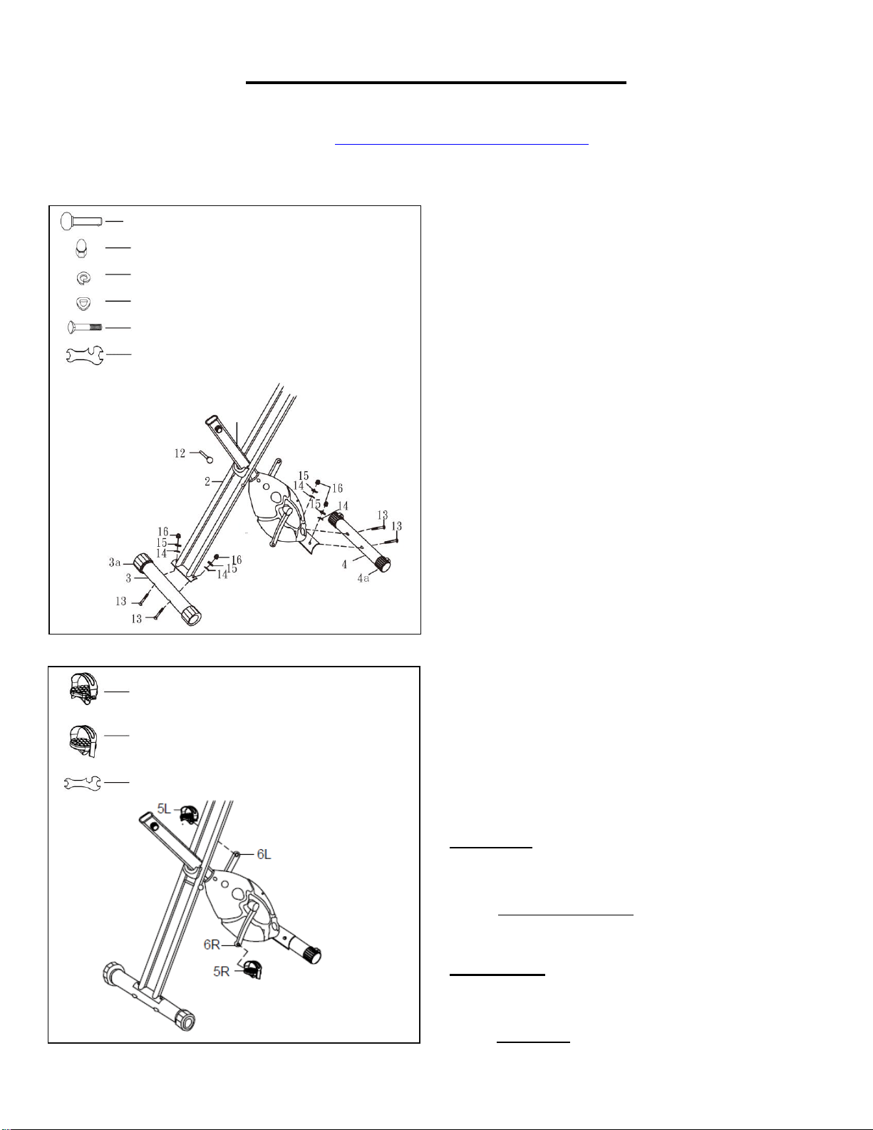
STEP 1:
Remove Locking Pin (No. 12) from Rear
Frame (No. 2). Unfold the Main Frame (No. 1)
and Rear Frame (No. 2). Secure the position
using Locking Pin (No. 12).
Attach the Rear Stabilizer (No. 3) to the Rear
Frame (No. 2) with 2 Carriage Bolts (No. 13), 2
Curved Washers (No. 14), 2 Spring Washers
(No. 15), and 2 Dome Nuts (No. 16). Tighten
and secure with Spanner (No. 31).
Repeat this process for the Front Stabilizer
(No. 4) and tighten all nuts and bolts securely
with Spanner (No. 31).
STEP 2:
Connect the Left & Right Pedals (No. 5L/R) to
the Left & Right Cranks (No. 6L/R). Before you
begin, turn the Tension Control Knob (No. 11)
all the way to the right until the crank arms are
immobilized.
Left Pedal: Align the Left Pedal (No. 5L) to the
Left Crank (No. 6L) at 90 degrees. Gently
insert the pedal in the crank arm and turn the
pedal counter-clockwise and use Spanner (No.
31).
Right Pedal: Align the Right Pedal (No. 5R) to
the Right Crank (No. 6R) at 90 degrees. Gently
insert the pedal in the crank arm and turn the
pedal clockwise and use Spanner (No. 31).
#12 M10x105mm 1pc
#16 M8 4pcs
#15 Φ8x1.5 4pcs
#14 Φ8x1.5 4pcs
#13 M8x65mm 4pcs
#31 S13, 14, 15 1pc
#5L Pedal 1pc
#5R Pedal 1pc
#31 S13, 14, 15 1pc
1
5
We value your experience using Sunny Health and Fitness products. For assistance with parts or
troubleshooting, please contact us at suppo[email protected] or 1-877-90SUNNY (877-907-
8669).
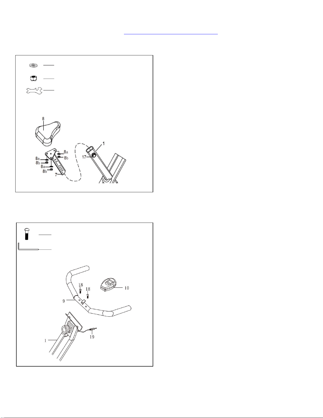
STEP 3:
Remove 3 Flat Washers (No. 8a) and
3 Nylon Nuts (No. 8b) from the Seat
(No. 8).
Attach the Seat (No. 8) to the Seat
Support (No. 7) with 3 Flat Washers
(No. 8a) and 3 Nylon Nuts (No. 8b) that
were removed. Tighten and secure with
Spanner (No. 31).
Loosen the Adjustment Knob (No. 17)
and slide the Seat Support (No. 7) into
the Main Frame (No. 1). Set the Seat
(No. 8) to the desired height then re-
tighten the Adjustment Knob (No. 17).
STEP 2:
17).
STEP 4:
Attach the Handlebar (No. 9) to the
handlebar support on the Main Frame
(No. 1) with 2 Allen Bolts (No. 18).
Tighten and secure with Allen Wrench
(No. 20).
Attach the Exercise Monitor (No. 10)
onto the mounting tab on the Handlebar
(No. 9). Connect the Sensor Wire (No.
19) to Exercise Monitor (No. 10).
#8a Φ8 x 1.5 3pcs
#8b M8 3pcs
#31 S13, 14, 15 1pc
#20 S5 1pc
#18 M8 x 35mm 2pcs
6
We value your experience using Sunny Health and Fitness products. For assistance with parts or
troubleshooting, please contact us at suppo[email protected] or 1-877-90SUNNY (877-907-
8669).
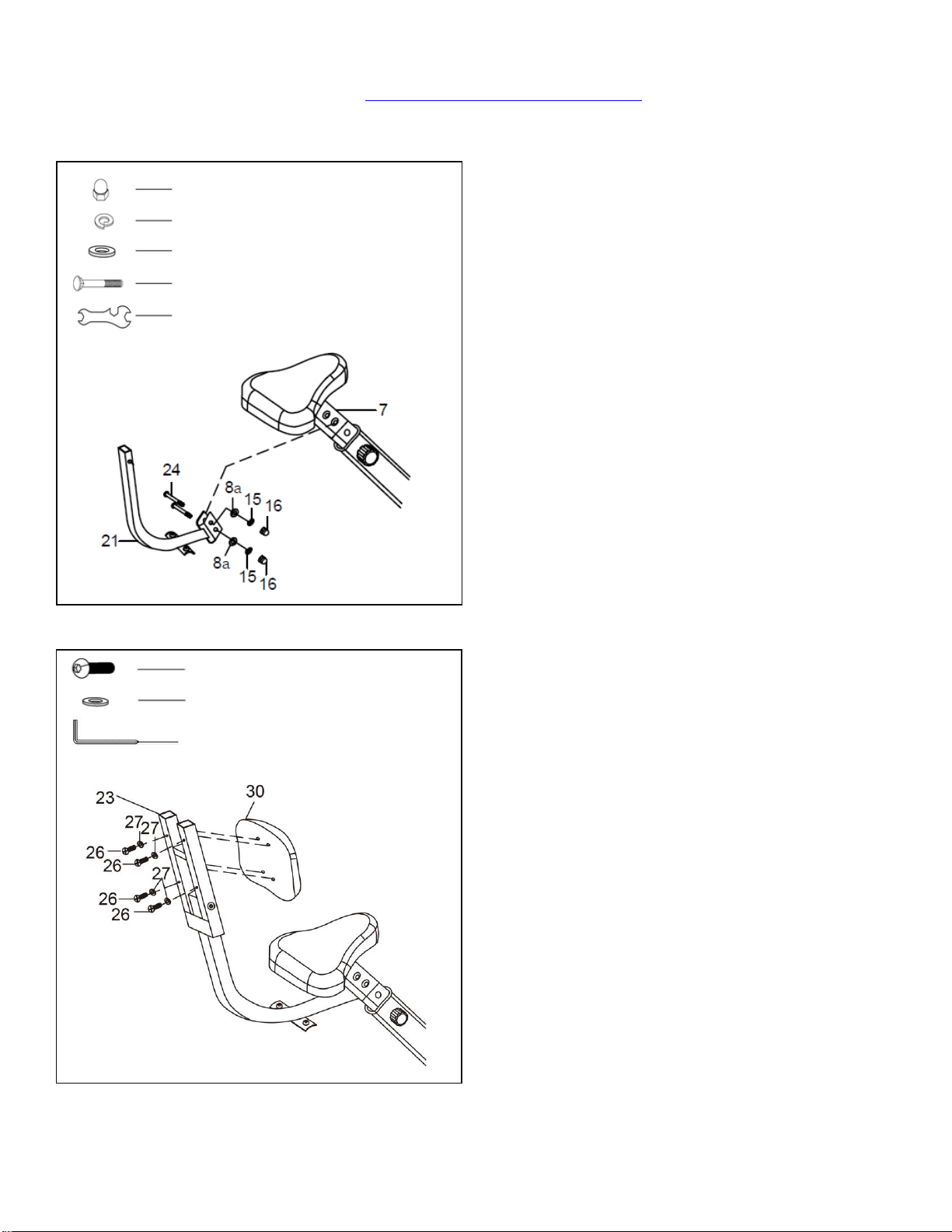
STEP 5:
Remove 2 Flat Washers (No. 8a), 2
Dome Nuts (No. 16), 2 Carriage Bolts
(No. 24), and 2 Spring Washer (No. 15)
from Back Support Frame (No. 21).
Attach the Back Support Frame (No.
21) to the Seat Support (No. 7) with 2
Flat Washers (No. 8a), 2 Dome Nuts
(No. 16), 2 Carriage Bolts (No. 24), and
2 Spring Washer (No. 15). Tighten and
secure with Spanner (No. 31).
STEP 6:
Attach the Backrest (No. 30) to the
Backrest Support (No. 23) with 4 Flat
Washers (No. 27) and 4 Screws (No.
26) that were removed. Tighten and
secure with Allen Wrench (No. 20).
#16 M8 2pcs
#15 Φ8 x 1.5 2pcs
#8a Φ8 x 1.5 2pcs
#24 M8 x 45mm 2pcs
#31 S13, 14, 15 1pc
#26 M6 x 40mm 4pcs
#27 Φ6.5 x 1.5 4pcs
#20 S5 1pc
7
We value your experience using Sunny Health and Fitness products. For assistance with parts or
troubleshooting, please contact us at suppo[email protected] or 1-877-90SUNNY (877-907-
8669).
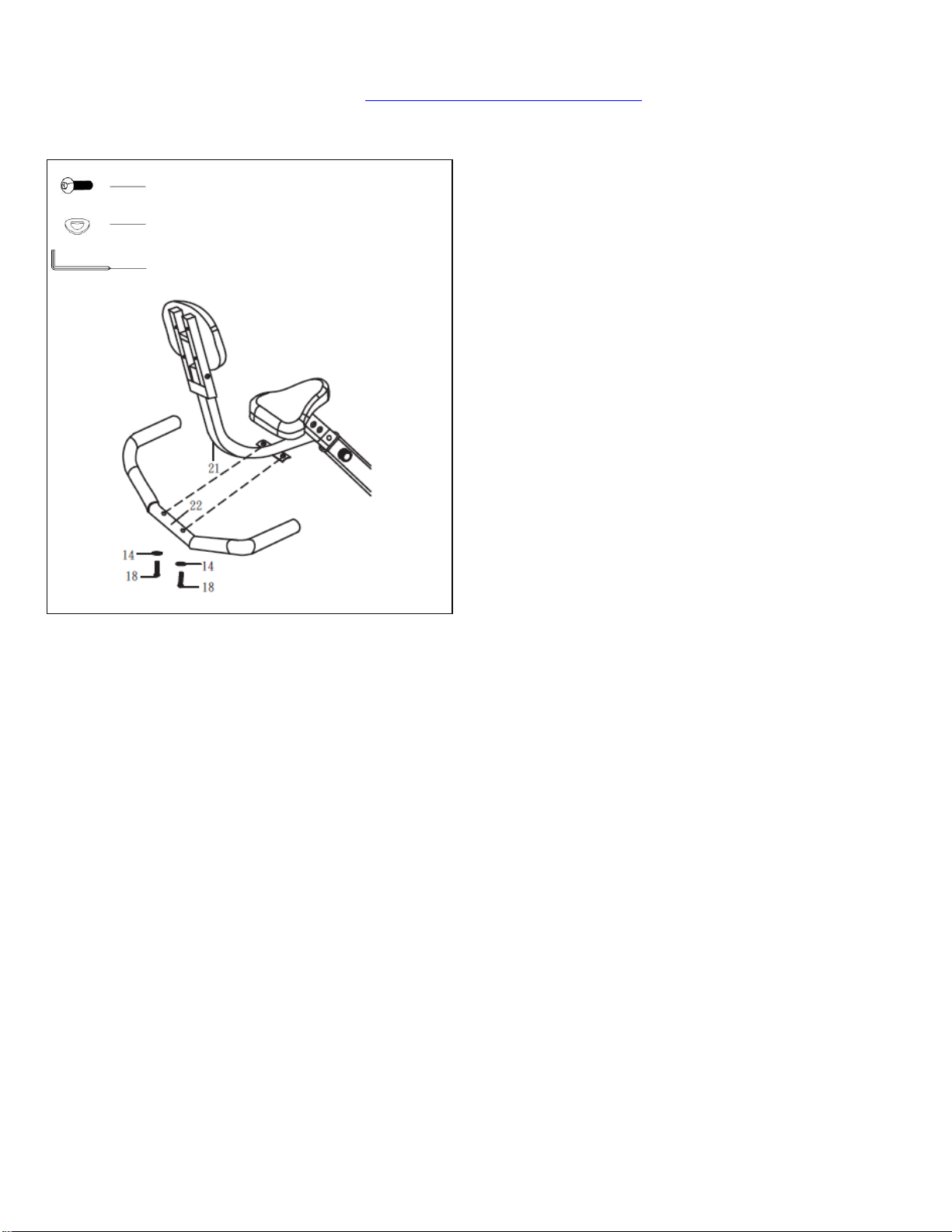
STEP 7:
Remove 2 Allen Bolts (No. 18) and 2
Curved Washers (No. 14) from the
Back Support Frame (No. 21).
Attach the Rear Handlebar (No. 22) to
the Back Support Frame (No. 21) with
2 Allen Bolts (No. 18) and 2 Curved
Washers (No. 14). Tighten and secure
with Allen Wrench (No. 20).
The assembly is complete!
#18 M8 x 35 mm 2pcs
#14 Φ8 x 1.5 2pcs
#20 S5 1pc
8
ADJUSTMENT INSTRUCTIONS
3
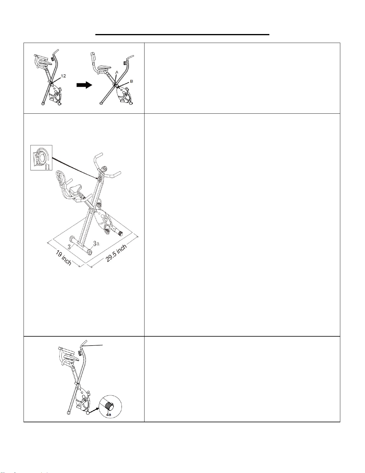
HOW TO FOLD THE BIKE
Pull out Locking Pin (No. 12). Fold the bike. Insert
Locking Pin (No. 12) into position B.
HOW TO ADJUST THE RESISTANCE
To ensure smooth and efficient cycling motions, the
belt tension braking system on your folding recumbent
bike has been pre-tensioned by our factory during
production.
To adjust the tension during use, turn the Tension
Control Knob (No. 11) clockwise to increase the
tension. Turn the Tension Control Knob (No. 11)
counter-clockwise to decrease the level of tension.
HOW TO ADJUST THE BALANCE
For security and stability, your folding recumbent bike
has a factory welded frame and once properly
assembled, should not need further alignment.
However, in the interest of safety, please always
ensure it is positioned on a solid, flat surface.
If necessary, use a rubber mat underneath to reduce
the possibility of slipping while in use.
If you need to adjust in order to level your bike, simply
turn the end of the Adjustable End Caps (No. 3a) on
the Rear Stabilizer (No. 3) to compensate for uneven
floors.
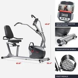
HOW TO MOVE THE BIKE
The Front End Caps (No. 4a) have wheels. When the
bike is folded, hold the Handlebars (No. 9) and tilt the
bike forward. You can transport the bike to the desired
location.
9
9
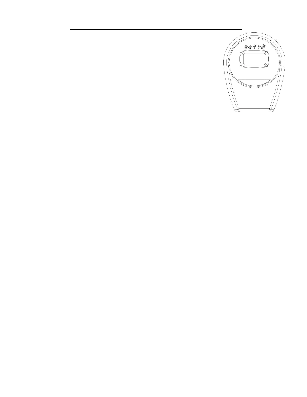
EXERCISE MONITOR INSTRUCTION
TIME ...................................................................................00:00-99:59
SPEED (SPD) .....................................................................0.0-99.9 MI/H
DISTANCE (DIST)...............................................................0.00-999.9 MI
CALORIES (CAL) ...............................................................0.0-999.9 KCAL
KEY FUNCTIONS:
MODE: Press to select and lock into a function.
CLEAR (RESET): Resets the values to zero by pressing and holding for 3 seconds.
OPERATING PROCEDURES:
AUTO ON/OFF: The monitor will activate when you press any button or start pedaling. If the machine
is inactive for 4 minutes, the monitor will automatically turn off.
RESET: Press and hold the button for 3 seconds to reset all values. The monitor can be reset by
changing the batteries or pressing the MODE button for 3 seconds.
MODE: To choose between SCAN and LOCK - if you do not want to use scan mode, press the
MODE button until the pointer is on the function you want.
FUNCTIONS:
TIME: Counts the total time of an exercise from 00.00-99.59.
SPEED: Displays current training speed.
DISTANCE: Accumulates the workout distance from 0.00 up to 999.9 miles.
CALORIE: Counts the total calories burned during an exercise from start to finish.
SCAN: Automatically scans through each function in the sequence.
BATTERY:
If there is a problem with the monitor display, change the batteries. This item requires 2 AA batteries.
When you change the batteries, change both at the same time. Do not mix old and new batteries.
Dispose the batteries according to your state and local guidelines.
Version 1.9