
1
IMPORTANT SAFETY INFORMATION
We thank you for choosing our product. To ensure your safety and health, please use this
equipment correctly. It is important to read this entire manual before assembling and using
the equipment. Safe and effective use can only be achieved if the equipment is assembled,
maintain and used properly. It is your responsibility to ensure that all users of the equipment
are informed of all warnings and precautions.
1. Before starting any exercise program, you should consult your physician to determine if
you have any medical or physical conditions that could put your health and safety at risk
or prevent you from using the equipment properly. Your physician’s advice is essential if
you are taking medication that affects your heart rate, blood pressure or cholesterol level.
2. Be aware of your body’s signals. Incorrect or excessive exercise can damage your health.
Stop exercising if you experience any of the following symptoms: pain, tightness in your
chest, irregular heartbeat, shortness of breath, lightheadedness, dizziness or feelings of
nausea. If you do experience any of these conditions, you should consult your physician
before continuing with your exercise program.
3. Keep children and pets away from the equipment. The equipment is designed for adult
use only.
4. Use the equipment on a solid, flat level surface with a protective cover for your floor or
carpet. To ensure safety, the equipment should have at least 2 feet (60 CM) of free space
all around it.
5. Ensure that all nuts and bolts are securely tightened before using the equipment. The
safety of the equipment can only be maintained if it is regularly examined for damage
and/or wear and tear.
6. Always use the equipment as indicated. If you find any defective components while
assembling or checking the equipment, or if you hear any unusual noises coming from
the equipment during exercise, discontinue use of the equipment immediately and do not
use until the problem has been rectified.
7. Wear suitable clothing while using the equipment. Avoid wearing loose clothing that may
become entangled in the equipment.
8. Do not place fingers or objects into the moving parts of the equipment
9. The maximum weight capacity of this unit is 275 pounds (125 KG).
10. The equipment is not suitable for therapeutic use.
11. To avoid bodily injury and/ or damage to the product or property, proper lifting and moving
is required.
12. Your product is intended for use in cool and dry conditions. You should avoid storage in
extreme cold, hot or damp areas as this may lead to corrosion and other related
problems.
13. This equipment is designed for indoor and home use only. It is not intended for
commercial use.
2
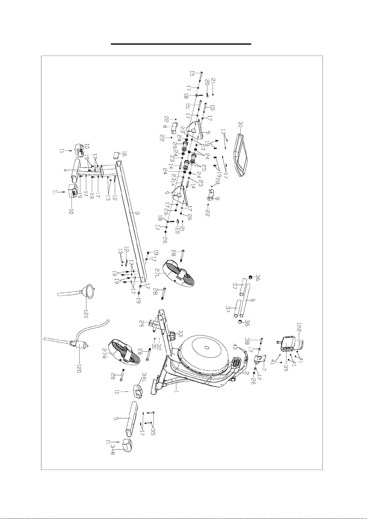
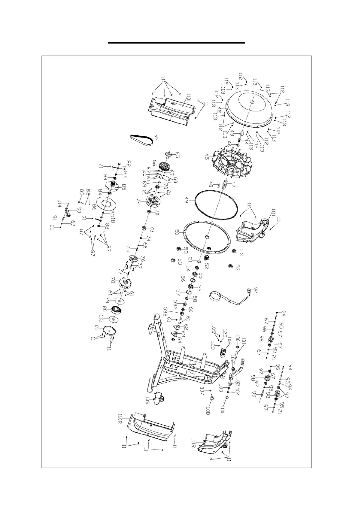
EXPLODED DIAGRAM 1
3
EXPLODED DIAGRAM 2
4
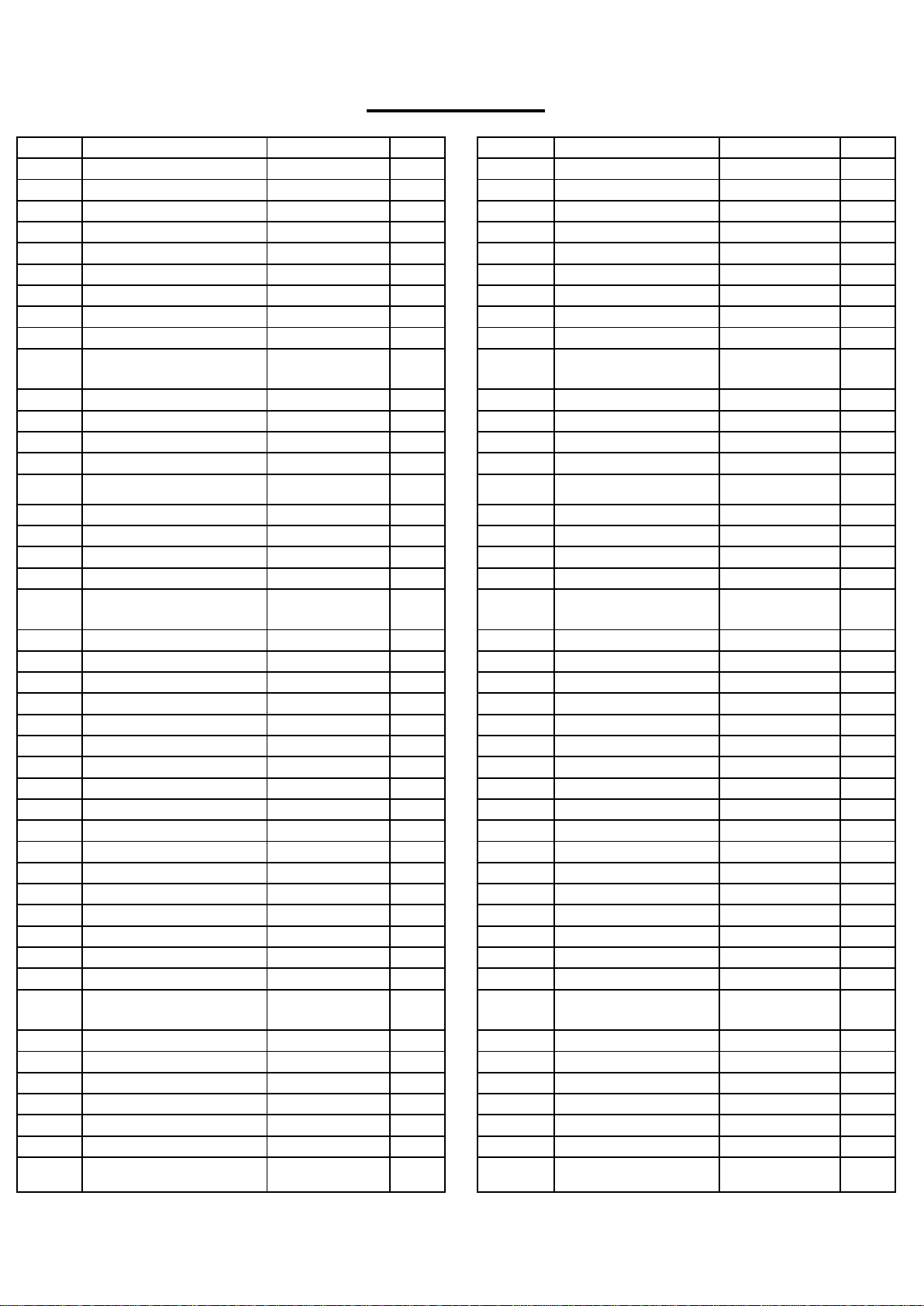
PARTS LIST
No.
Description
Spec.
Qty.
No.
Description
Spec.
Qty.
1
Main Frame
1
46
Flat Washer
D10xD30x2.5
1
2
Meter Support Tube
1
47
Rotating Axle
1
3
Slide Rail
1
48
Stainless Steel Pin
1
4
Rear Support Tube
1
49
Tray Sealing Ring
1
5
Front Stabilizer
1
50
Lower Tank Cover
1
6
Pull Bar
1
51
O Shape Washer
1
7
Meter Plate
1
52
Plug
1
8
U Shape Baffle
2
53
Knob
4
9
Supporting Board
2
54
Skeleton Oil Seal
1
10
Adjustable Rear End
Cap
2 55 Bearing 6005 2
11
Screw
ST4.2x18
25
56
Spacer
1
12
Limit Cushion
2
57
Hole Washer
1
13
Screw
M6x10
4
58
Axle Washer
1
14
Spacer
3
59A/B
Coupler 1
2
15 Hex Bolt M8x125 3 60 Coupler 2 1
16
Square Cap
1
61
Bolt
M6x12
10
17
Flat Washer
D8xD20x1.5
24
62
Fixed Plate
1
18
Adjustable Chain Bolt
4
63
Bearing Plate
1
19
Screw
M8×15
14
64
Bearing
6001
1
20
Adjustable Chain U
Mat
2 65 Center Axle 1
21
Nylon Nut
M6
10
66
Belt Pulley
1
22
Screw
M5x7
4
67
Flat Washer
D6xD12x1.2
8
23
Roller Spacer
6
68
Spring Washer
D6
4
24
Bearing
6
69
Axle Washer
1
25
Roller
3
70
Bearing
16003
2
26
Nylon Nut
M8
4
71
Hex Screw
M6
2
27L/R
Pedal
1 pr.
72
Belt Wheel
1
28
Hex Bolt
M12x160
4
73
Bearing
1
29
Square Cap
1
74
Flat Washer
D6xD20x2
1
30
Seat
1
75
Screw
M6x18
1
31
Screw
1
76
Volute Spring Axle
1
32
Flat Washer
1
77
Screw
M6x35
5
33
Tension Control
1
78
Volute Wheel
1
34L/R
Front End Cap
1 pr.
79
PC Board 1
1
35
Screw
M8x55
2
80
Volute Spring
1
36
Round Cap
2
81
Belt Wheel Cover
1
37
Foam Grip
2
82
Flange Nut
M10x1
2
38 Screw M8X70 1 83
Hex Conical Thin
Nut
M10x1 2
39
Meter
1
84
Bearing
6000
2
40
Sensor Wire
2
85
Plastic Belt Wheel
1
41
Screw
M5X10
6
86
Aluminum Ring
1
42
Upper Tank Cover
1
87
Screw
ST4.2x16
8
43
Cap
1
88
Screw
M5
2
44
Screw
M10x30
1
89
Hex Bolt
M5x35
1
45 Impeller 1 90 Magnetic Board 1
5
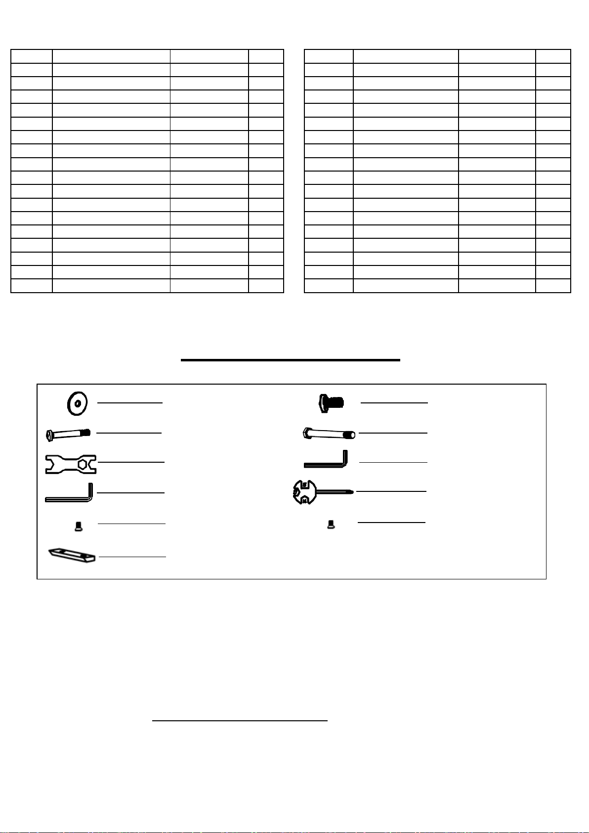
HARDWARE PACKAGE
Ordering Replacement Parts (U.S. and Canadian Customers only)
Please provide the following information in order for us to accurately identify the part(s)
needed:
The model number (found on cover of manual)
The product name (found on cover of manual)
The part number found on the “EXPLODED DIAGRAM” and “PARTS LIST” (found near
the front of the manual)
Please contact us at support@sunnyhealthfitness.com or 1- 877 – 90SUNNY(877-907-8669).
No.
Description
Spec.
Qty.
No.
Description
Spec.
Qty.
91
Magnetic Board Axle
1
108
Adjustable Knob
1
92
Mesh Belt
1
109
Decoration Cover
1
93
Belt
1
110L/R
Belt Cover 1
1 pr.
94
Hex Bolt
M6x90xL20
2
111L/R
Belt Cover 2
1 pr.
95
Axle Washer
6
112
Screw
M4x12
12
96
Belt Wheel Axle
2
113
Flat Washer
D4xD9x1
12
97
Bearing
6000
6
114
Screw
M6x35
1
98
Belt Roller
3
115
PC Board 2
1
99
Belt Wheel Axle
1
116
Wrench
S=17,19
1
100
Hole Cover
2
117
Allen Wrench
S=5
1
101
Bolt
Ф19.2x96
1
118
Allen Wrench
S=6
1
102
Axle Sleeve
2
119
Spanner
S=13,14,15
1
103
Flat Washer
D8xD16x1.5
1
120
Pumping Siphon
1
104
Nylon Nut
M8
1
121
Funnel
1
105
Screw
M5x15
2
122
Tablet Holder
1
106
Pull Bar Fixed Plate
1
123
Flat Washer
D5XD10X1
2
107
Hex Screw
M8
1
#35 M8x55 2PCS
#19 M8x15 10PCS
#28 M12x160 4PCS
#116 S=17,19 1PC
#117 S=5 1PC
#118 S=6 1PC
#119 S=13,14,15 1PC
#17 D8 12PCS
#13 M6x10 2 PCS
#41 4PCS
#12 1PC
6
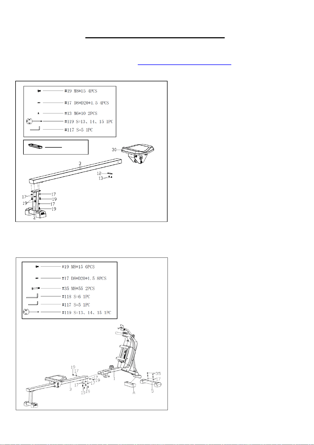
ASSEMBLY INSTRUCTIONS
We value your experience using Sunny Health and Fitness products. For assistance with parts or
(877-907-8669).
STEP 1:
Remove the pre-assembled Limit
Cushion (No. 12) and 2 Screws (No.
13) from the Slide Rail (No. 3) using
Spanner (No. 119).
Slide the Seat (No. 30) to the Slide Rail
(No. 3), make sure Seat (No. 30)
through the position of Limit Cushion
(No. 12). Then attach the Limit
Cushion (No. 12) to the Slide Rail (No.
3) with 2 Screws (No. 13) using
Spanner (No. 119).
Attach the Rear Support Tube (No. 4)
to the Slide Rail (No. 3) with 4 Screws
(No. 19) and 4 Flat Washers (No. 17)
using Allen Wrench (No. 117).
STEP 2:
Remove the Plastic Block (A) from the
Main Frame (No. 1) using Spanner
(No. 119). Attach the Front Stabilizer
(No. 5) to the Main Frame (No. 1) with 2
Screws (No. 35) and 2 Flat Washers
(No. 17) using Allen Wrench (No. 118).
Attach the Slide Rail (No. 3) to the Main
Frame (No. 1) with 6 Screws (No. 19)
and 6 Flat Washers (No. 17) using
Allen Wrench (No. 117).
#12 1PC
7
We value your experience using Sunny Health and Fitness products. For assistance with parts or
troubleshooting, please contact us at support@sunnyhealthfitness.com or 1-877-90SUNNY
(877-907-8669).
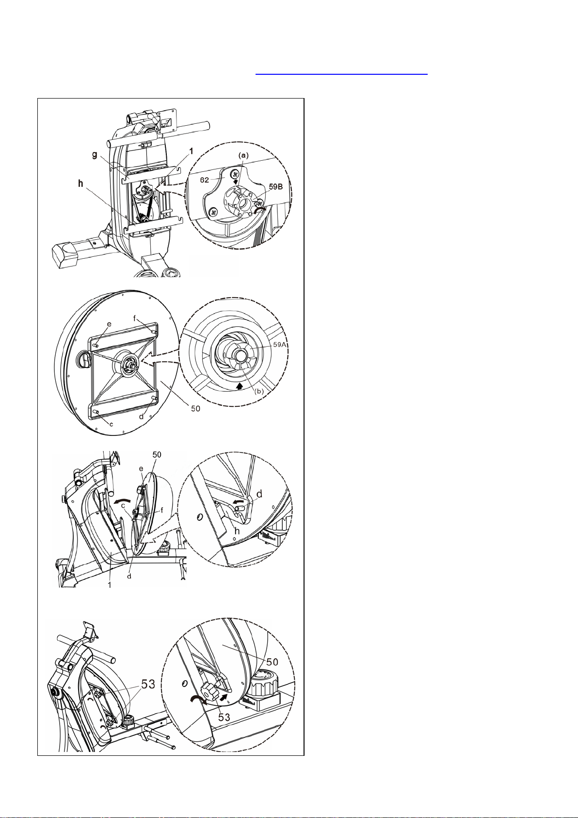
STEP 3:
Turn the Coupler (No. 59B) on the
Main Frame (No. 1) clockwise, keep
the gap (a) of the Coupler (No. 59B)
align to the red arrow shown on the
Fixed Plate (No. 62). (Fig. 1)
Note: The Coupler (No. 59B) can only
be turned clockwise.
Turn the Coupler (No. 59A) on the
Lower Tank Cover (No. 50), keep the
gap (b) of the Coupler (No. 59A) align
to the red arrow shown on the Lower
Tank Cover (No. 50). (Fig. 2)
Attach the
Lower Tank Cover (No.
50) to the Main Frame (No.1). There
are 4 bolts (c, d, e, and f)
on the
bottom and top of the
Lower Tank
Cover (No. 50). (Fig. 3)
Hang the 2 bolts (c and d) to the
bottom steel plate (h) of the Main
Frame (No. 1)
. Make sure the
remaining 2 bolts (e and f) hang to the
upper steel plate (g). Cover the Lower
Tank Cover (No. 50). Tight 4 Knobs
(No.53) to lock the Lower Tank Cover
(No. 50). (Fig. 4)
Fig. 1
Fig. 2
Fig. 3
Fig. 4
8
We value your experience using Sunny Health and Fitness products. For assistance with parts or
troubleshooting, please contact us at support@sunnyhealthfitness.com or 1-877-90SUNNY
(877-907-8669).
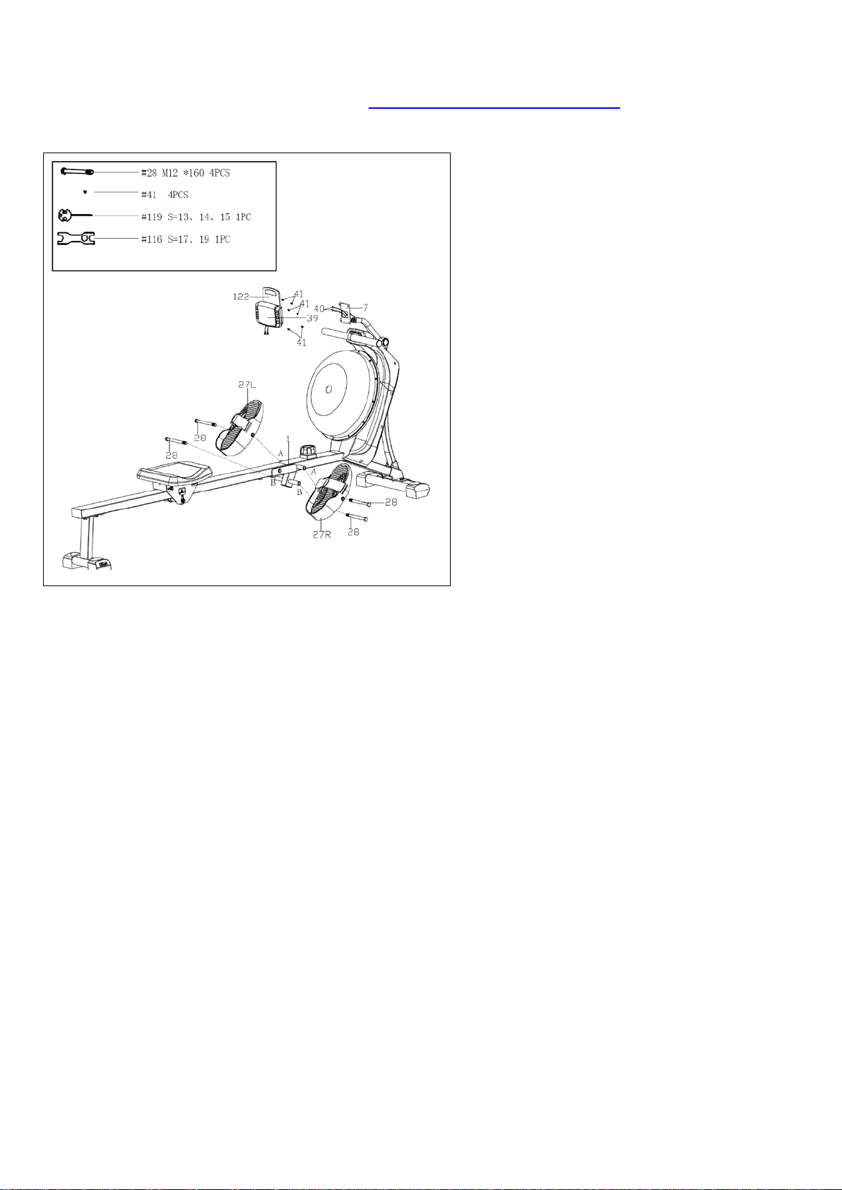
STEP 4:
Insert the 2 Hex Bolts (No. 28)
into the
bottom hole in position B of
Main Frame
(No. 1). Tighten with Wrench (No. 116).
Insert the 2 Hex Bolts (No. 28)
into the
upper hole in position A of
Main Frame
(No. 1) through the Pedals (No. 27L/R)
.
Tighten with Wrench (No. 116).
Note: The 2 Pedals (No. 27L/R)
should
rest on Hex Bolts (No. 28)
that are in
position B.
Remove 6 Screws (No. 41) from the
back Meter (No. 39) using
Spanner (No.
119).
Insert the Tablet Holder (No. 122)
to the
Meter (No. 39) and lock with 2
Screws
(No. 41) using Spanner (No. 119).
Connect the Sensor Wires (No. 40)
with
wires of Meter (No. 39)
. Then attach the
Meter (No. 39) to the
Meter Plate (No. 7)
with 4 Screws (No. 41)
that were just
removed by using Spanner (No. 119).
Note:
Put all wires to the meter tube
before attaching the Meter (No. 39)
to
Main Frame (No. 1).
The assembly is complete!
9
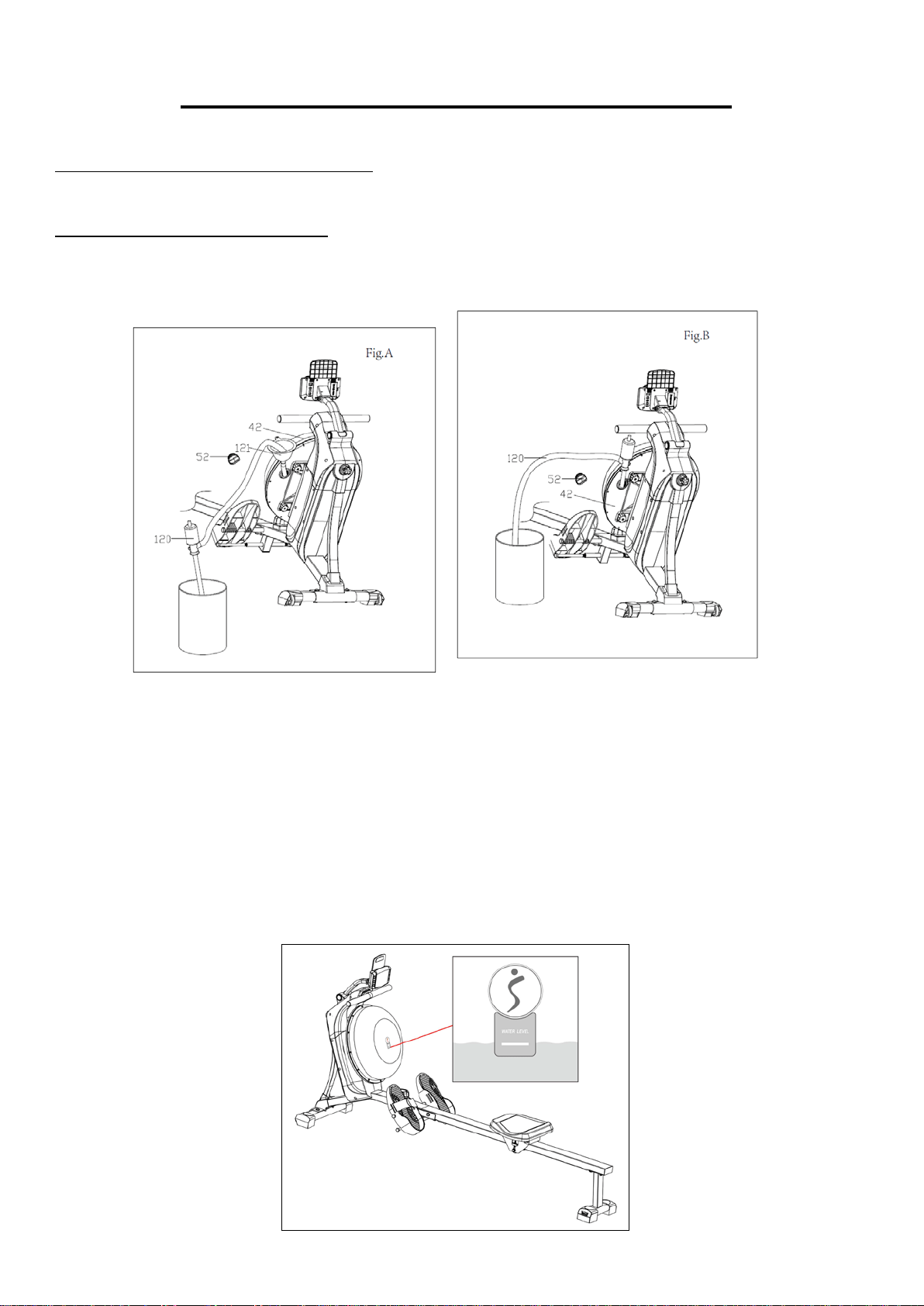
HOW TO FILL AND EMPTY THE TANK
1. Remove the Plug (No.52) from the Upper Tank Cover (No. 42).
2. To fill the tank with water, refer to Fig. A. Insert the Funnel (No. 121) into the tank, then use a cup or
a bucket and Pumping Siphon (No. 120) to fill the tank. Use the water level gauge on the front of
the tank to measure water level in the tank.
3. To empty the tank, refer to Fig. B. Place a bucket next to the rower and use the Pumping Siphon
(No. 120) to pump out the water from the tank into the bucket.
4. Insert the Plug (No. 52) back into the Upper Tank Cover (No. 42). Wipe off excess water around the
area.
NOTE:
• Fill the tank only with tap water. Add 1 water purification tablet (1 packet is included). Never use
pool chlorine or chlorine bleach. This will damage the tank and void the warranty.
• Add a water purification tablet every 6 months or as needed. If water remains cloudy, replace the
water in the tank.
• Do not consume the tank water. Dispose the water after pumping it out from the tank.
WATER LEVEL
• The water level gauge is on the front of the tank. Please fill the water until it reaches the limit (white
line). The water level should not be higher or lower than this limit. Never fill over this limit. Filling the
tank over the limit will void the warranty.
10
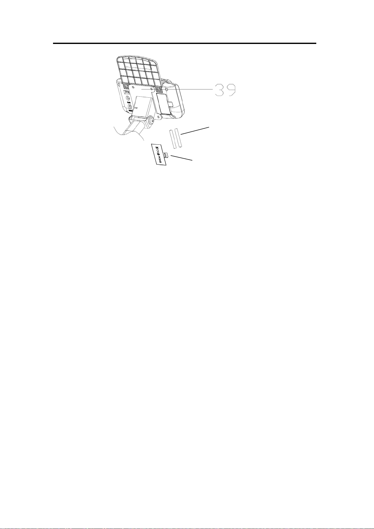
BATTERY INSTALLATION & REPLACEMENT
BATTERY INSTALLATION:
1. Take out 2 AA batteries from meter box.
2. Press the buckle of battery cover on the back of the Meter (No. 39), then remove battery
cover.
3. Install 2 AA batteries into the battery case on the back of the Meter (No. 39). Pay attention
to the battery + and – poles before installing.
4. Press the buckle of battery cover, then put the battery cover back to the back of the Meter
(No. 39).
5. The installation is complete!
BATTERY REPLACEMENT:
1. Press the buckle of battery cover on the back of the Meter (No. 39), then remove battery
cover.
2. Remove the 2 old AA batteries in the battery case and install 2 new AA batteries into the
battery case on the back of the Meter (No. 39). Pay attention to the battery + and – poles
before installing.
3. Press the buckle of battery cover, then put the battery cover back to the back of the Meter
(No. 39).
4. The replacement is complete!
NOTE: Always change both batteries at the same time. Do not mix battery types and do not
mix old and new batteries. Dispose batteries according to your state and regional guidelines.
Battery Cover
Battery
11
ADJUSTMENTS GUIDE
ADJUSTING THE BALANCE
Adjust the Adjustable Rear End Caps (No. 10) on the
Rear Support Tube (No. 4) of the rower if the rower is
unbalanced during use.
CAUTION!
Moving parts, such as the Seat (No. 30), can crush and
cut. Keep hands clear of the Slide Rail (No. 3) during
!
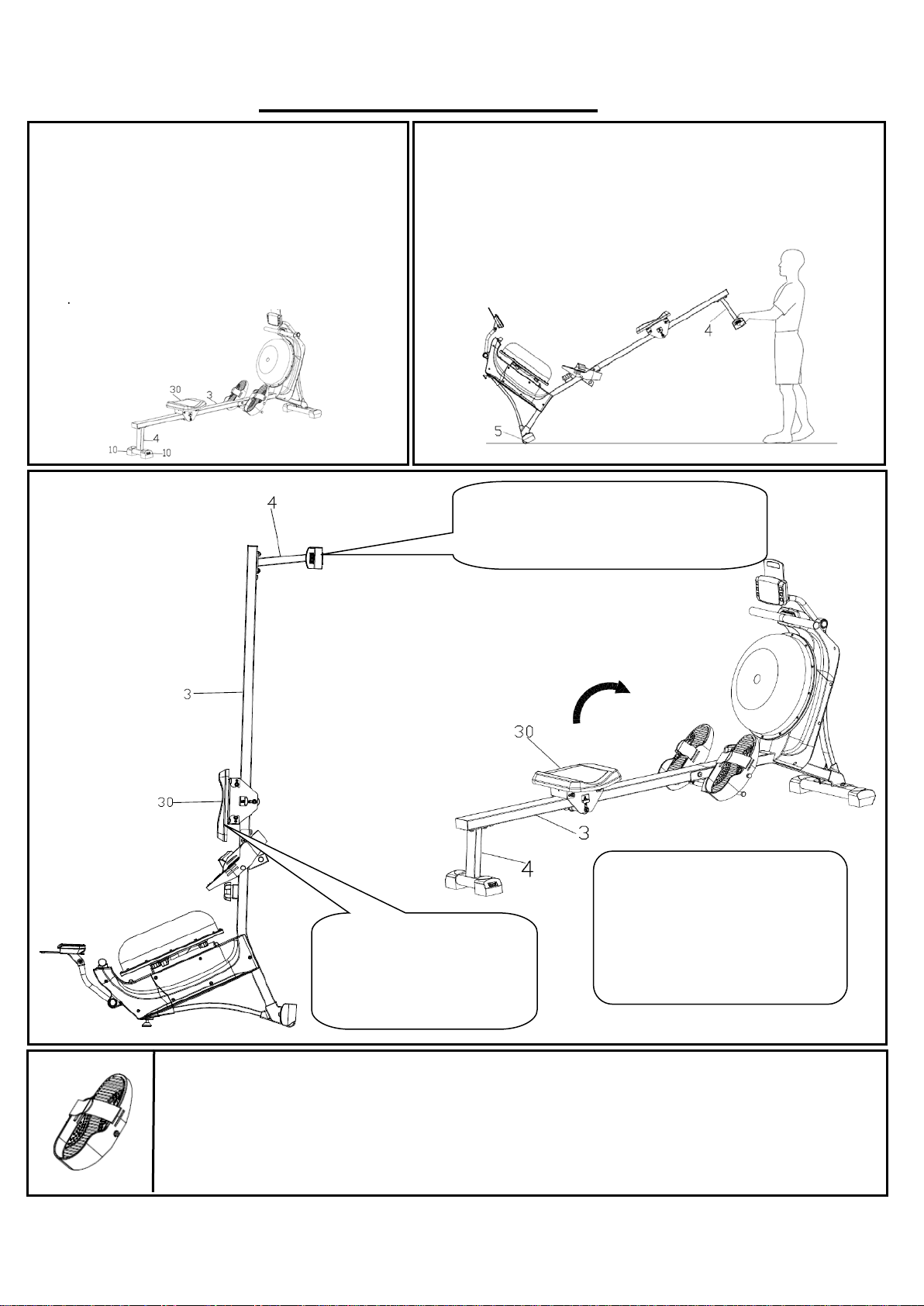
STORAGE
MOVING THE ROWER
To move the rower, lift up the Rear Support Tube (No. 4) until the
transportation wheels on the Front Stabilizer (No. 5) touch the ground.
With the wheels on the ground, you can transport the rower to the
desired location with ease.
PEDAL ADJUSTMENT
The pedal strap is adjustable and can be personalized to fit the user’s foot size.
CAUTION!
Move the Seat (No.30) to the
front of Slide Rail (No.3) first
or it will glide down when
raising the rower up!
CAUTION!
Move with caution when you raise the rower
up, as your head may touch the Rear
Support Tube (No. 4).
When not in use, you can save
space by storing the rower
vertically. Lift by the Rear
Support Tube (No. 4) to raise the
rower to a vertical position.
If not using the rower for more
than a month, empty the tank
before storing.
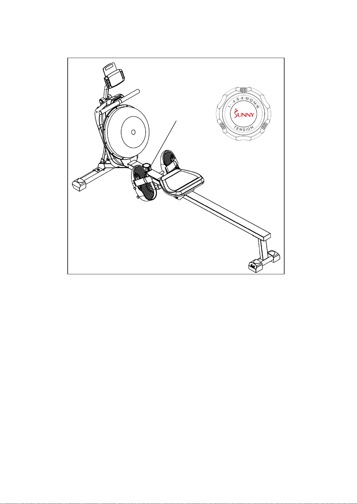
12
ADJUSTING THE RESISTANCE
Rotate the Tension Control (No. 33) clockwise to increase the level of resistance. Rotate
the Tension Control (No. 33) counter-clockwise to decrease the level of resistance.
33
13
EXERCISE METER
Our computerized exercise meter on the Sunny Water Rowing Machine allows the user to tailor a
personalized workout by monitoring their progress. During a workout, the display console will
alternately and repeatedly display the Time, Time/500M, SPM, Distance, Strokes, Total Strokes,
Calories Burned, and Pulse.
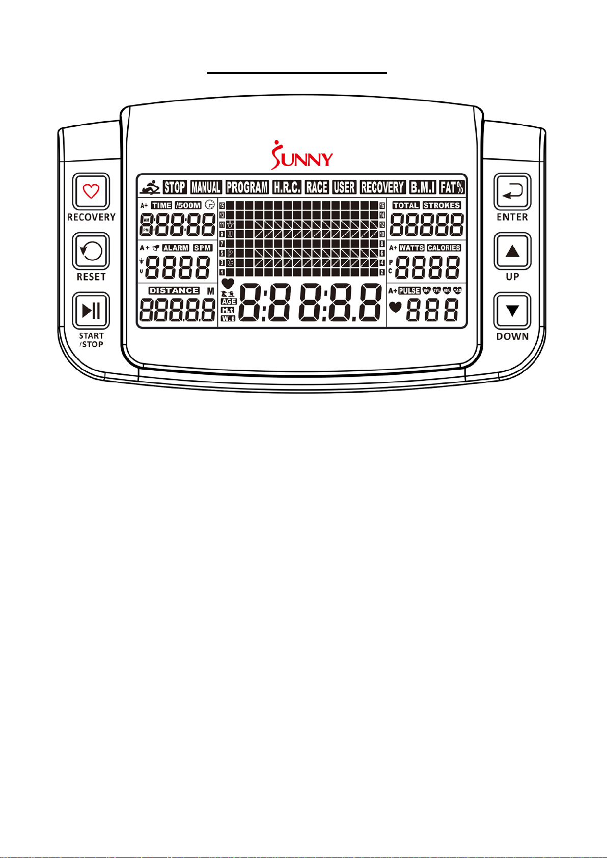
BUTTONS
UP▲/DOWN ▼
Press these two buttons to scroll through the available selection.
To adjust the function values upward and downward.
ENTER:
To confirm your selection.
During training, press this button to scan each display function.
START /STOP:
To start and stop your selected workout program.
RESET:
To return the meter back to the main menu.
Press and hold for 3 seconds to reset values.
RECOVERY:
To activate the RECOVERY PROGRAM that will automatically evaluate your fitness immediately
after workout.
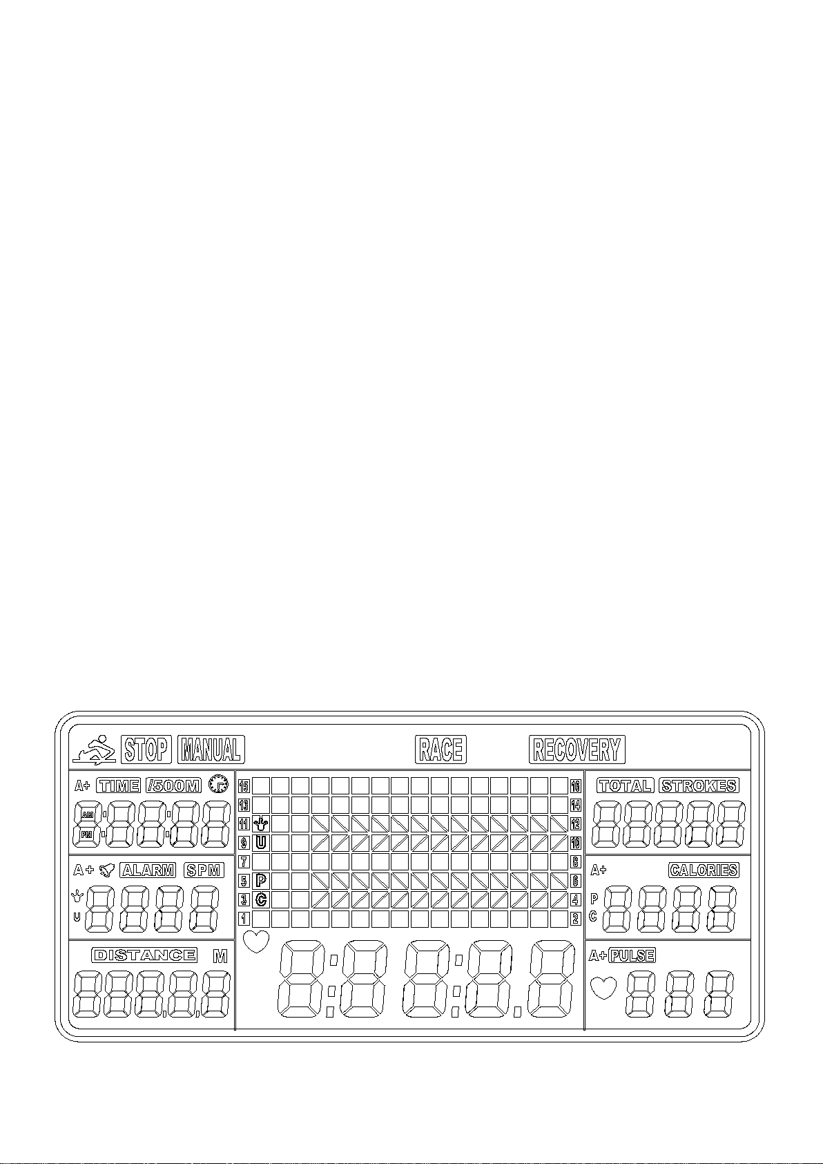
14
FUNCTIONS
TIME: Set target time (1 min ~ 99 min) by pressing UP and DOWN buttons, in 1 minute
increments.
TIME/500M: Your average 500M time is automatically displayed.
SPM: Strokes per minute.
DISTANCE: Preset target distance (100 ~ 99900 meters) by pressing UP and DOWN buttons, in
100 meters increments.
STROKES: Set target stroke (10 ~ 9990 strokes) by pressing UP and DOWN buttons, in 10
strokes increments.
TOTAL STROKES: Accumulates total strokes from 0 to 9999.
CALORIES: Set target calories (10 ~ 9990 Cal) by pressing UP or DOWN buttons, in 10 Cal
increments.
HRC/PULSE: Displays heart rate.
In Manual Mode, set target pulse by pressing UP and DOWN buttons (30 ~ 240), in 1 BPM
increments. HRC will display at the top of the meter. The meter will display your heart rate during
training. When it reaches the target value, PULSE will flash, and the meter will beep until it is
changed to another mode or you remove the chest strap. Pulse measurement function only
works with 5.3 KHz chest strap heart rate monitors.
CALENDAR: The meter will display year, month, and day when meter is in sleep mode.
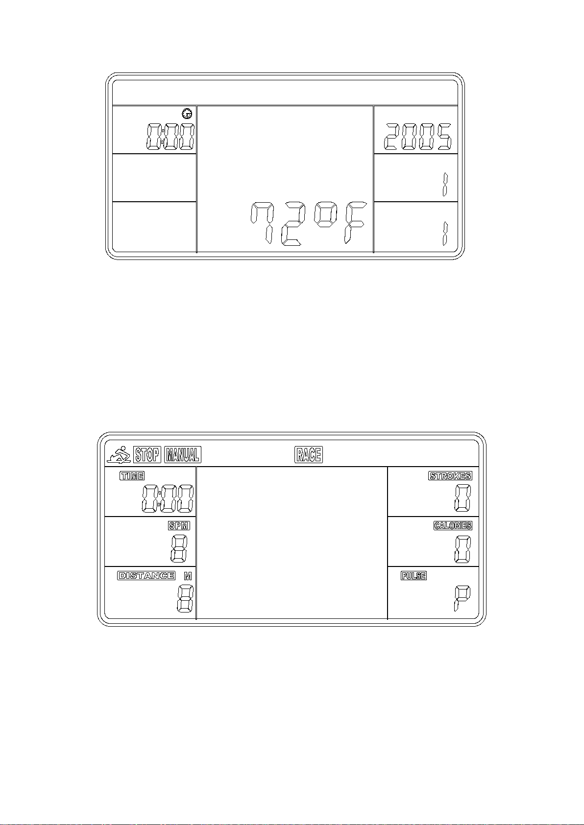
TEMPERATURE: The meter will display current room temperature when the meter is in sleep
mode.
CLOCK: The meter will display current time when the meter is in sleep mode.
Note: Chest Strap Heart Rate Monitor is not included.
OPERATION
1. Install 2 PCS AA batteries (included) and meter will beep for 2 seconds (Fig.1).
Then, the meter enters into the CLOCK & CALENDAR MODE (Fig.2).
Fig. 1
15
2. The CLOCK will flash. Press UP button to set the hour. Press ENTER to confirm.
Press UP to set the minutes. Press ENTER to confirm. Continue press UP button to set the
YEAR (in the STROKES window); MONTH (in the CALORIES window); DAY (in the PULSE
window). Press ENTER to confirm when it is set.
After you confirm it, the ALARM will beep. Press ENTER to skip setting up the alarm. To set up
the alarm, press UP button to turn on ALARM. An arrow will appear next to ALARM. Press
ENTER. CLOCK window will flash. Press UP or DOWN buttons to set the alarm time. Press
ENTER to confirm. Meter will go into the SPORT screen (Fig. 3).
Fig. 3
3. When you enter the SPORT screen, MANUAL and RACE will flash. Press UP or DOWN to
select MANUAL or RACE. Press ENTER to confirm your selection.
(1) MANUAL (Fig. 4): There are 2 options in MANUAL mode.
a. The meter can be set to countdown. When you select MANUAL, the value of TIME will start
to flash. Press UP to set the value of TIME to countdown. Press ENTER to confirm it. Press
Fig. 2
16
ENTER to skip setting up the time COUNTDOWN and go to the next function. You can set
the values for DISTANCE, STROKES, CALORIES, or PULSE. (Note: You can only set the
value for one function to countdown. For example, if you have set the target value for
TIME, then DISTANCE can’t be set.)
Press START button to start and the STOP icon will disappear. When the countdown
reaches zero or you press STOP button, the meter will stop and display the average value.
b. The meter counts the value of your workout. Press START to start.
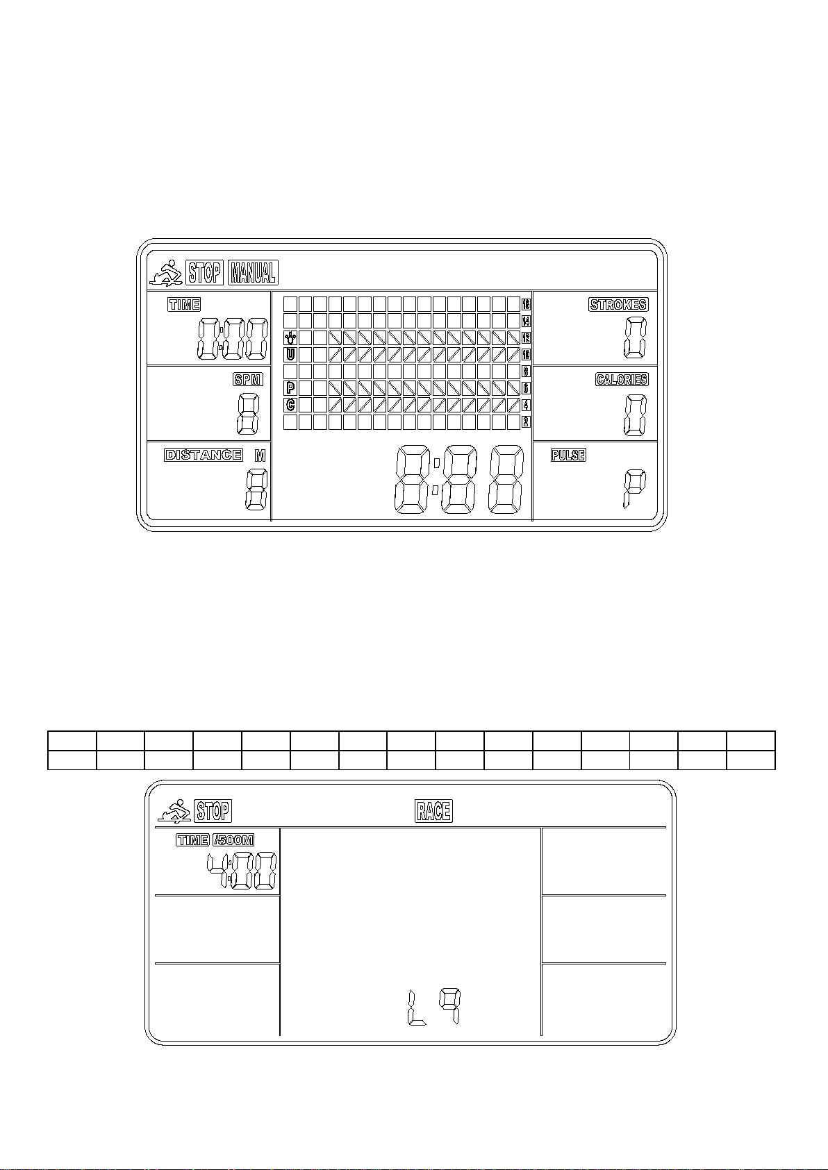
(2) RACE (Fig. 5):
Select RACE mode and L9 will flash. The TIME/500M will display 4:00. Then, press UP or
DOWN to select L1 ~ L15. Press ENTER to confirm. Then, you can set the distance of the race
(500 ~ 10000M) while the value of DISTANCE is blinking. Press ENTER, and the picture of the
race will display on the screen.
The TIME/500M of the programs are as follows:
L1
L2
L3
L4
L5
L6
L7
L8
L9
L10
L11
L12
L13
L14
L15
8:00
7:30
7:00
6:30
6:00
5:30
5:00
4:30
4:00
3:30
3:00
2:30
2:00
1:30
1:00
Fig.4
Fig.5
17
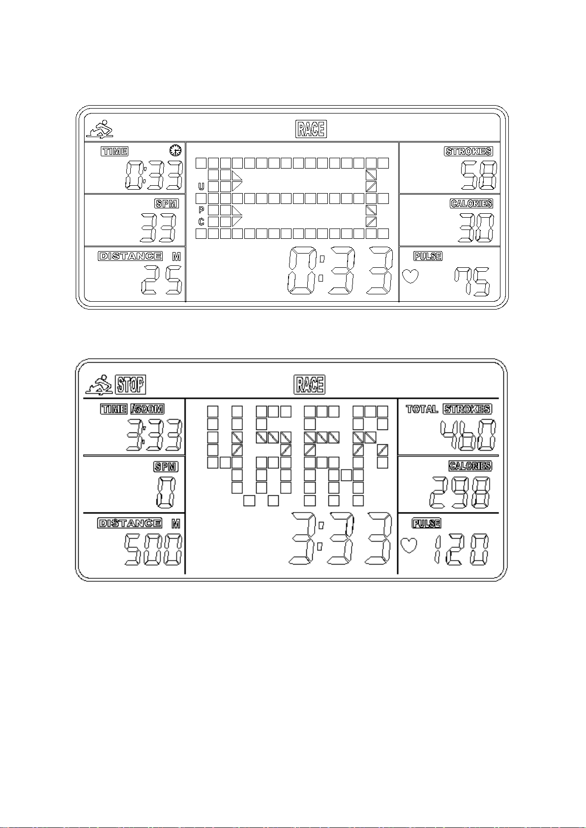
a. Press START button to start and STOP icon will disappear. USER and PC will display in the
matrix (Fig. 6). The meter will stop when either the user or meter has reached the race
distance that was set. Then, the matrix displays “PC WIN” or “USER WIN” (Fig. 7).
Fig. 7
b. When the race is over, you can press START to start a race once again. Press RESET to
leave the RACE screen.
(3) RECOVERY:
This meter works with a 5.3 KHz chest strap heart rate monitor (not included). After exercising
for a period of time, keep wearing the chest strap monitor and press RECOVERY button. All
function displays will stop except “TIME” starts counting down from 00:60 to 00:00.
Screen will display your heart rate recovery status with the F1, F2….to F6. F1 is outstanding. F6
is poor. User may keep exercising to improve the heart rate recovery status. (Press the
RECOVERY button again to return the main display.)
Fig. 6

18
ALARM
Alarm only works while the meter is in sleep mode. Alarm will not sound during exercise. Press
and hold RESET to go to clock screen to set up ALARM.
SLEEP MODE
The meter will go into sleep mode after about 4 minutes of inactivity.
BATTERY
This meter uses 2 AA batteries, which are included. Changing the batteries will reset all values.
If there is a problem with the display, try to change the batteries first. When changing the
batteries, change both. Do not mix battery types. Do not mix old and new batteries. Dispose of
old batteries according to your regional guidelines.
Version 1.2