CARBON PREMIUM AIR
MAGNETIC ROWING MACHINE
SF-RW5983
USER MANUAL
IMPORTANT! Please retain owner’s manual for maintenance and adjustment instructions.
Your satisfaction is very important to us, PLEASE DO NOT RETURN UNTIL YOU HAVE
CONTACTED US: [email protected] or 1- 877 - 90SUNNY (877-907-8669).

1
IMPORTANT SAFETY INFORMATION
We thank you for choosing our product. To ensure your safety and health, please use this
equipment correctly. It is important to read this entire manual before assembling and using the
equipment. Safe and effective use can only be achieved if the equipment is assembled,
maintained, and used properly. It is your responsibility to ensure that all users of the equipment
are informed of all warnings and precautions.
1. Before starting any exercise program, you should consult your physician to determine if you
have any medical or physical conditions that could put your health and safety at risk or prevent
you from using the equipment properly. Your physician’s advice is essential if you are taking
medication that affects your heart rate, blood pressure, or cholesterol level.
2. Be aware of your body’s signals. Incorrect or excessive exercise can damage your health.
Stop exercising if you experience any of the following symptoms: pain, tightness in your chest,
irregular heartbeat, shortness of breath, lightheadedness, dizziness, or feelings of nausea. If
you do experience any of these conditions, you should consult your physician before
continuing with your exercise program.
3. Keep children and pets away from the equipment. The equipment is designed for adult use
only.
4. Use the equipment on a solid, flat level surface with a protective cover for your floor or carpet.
To ensure safety, the equipment should have at least 2 feet (60 CM) of free space all around it.
5. Ensure that all nuts and bolts are securely tightened before using the equipment. The safety of
the equipment can only be maintained if it is regularly examined for damage and/or wear and
tear.
6. Always use the equipment as indicated. If you find any defective components while
assembling or checking the equipment, or if you hear any unusual noises coming from the
equipment during exercise, discontinue use of the equipment immediately and do not use until
the problem has been rectified.
7. Wear suitable clothing while using the equipment. Avoid wearing loose clothing that may
become entangled in the equipment.
8. Do not place fingers or objects into the moving parts of the equipment.
9. The maximum weight capacity of this unit is 265 pounds (120 KG).
10. The equipment is not suitable for therapeutic use.
11. To avoid bodily injury and/or damage to the product or property, proper lifting and moving are
required.
12. Your product is intended for use in cool and dry conditions. You should avoid storage in
extreme cold, hot or damp areas as this may lead to corrosion and other related problems.
13. This equipment is designed for indoor and home use only; it is not intended for commercial
use.
2
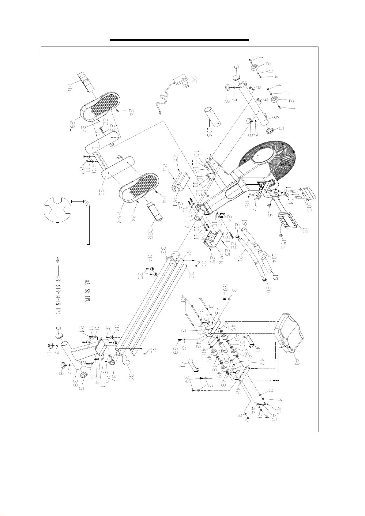
EXPLODED DIAGRAM 1
3
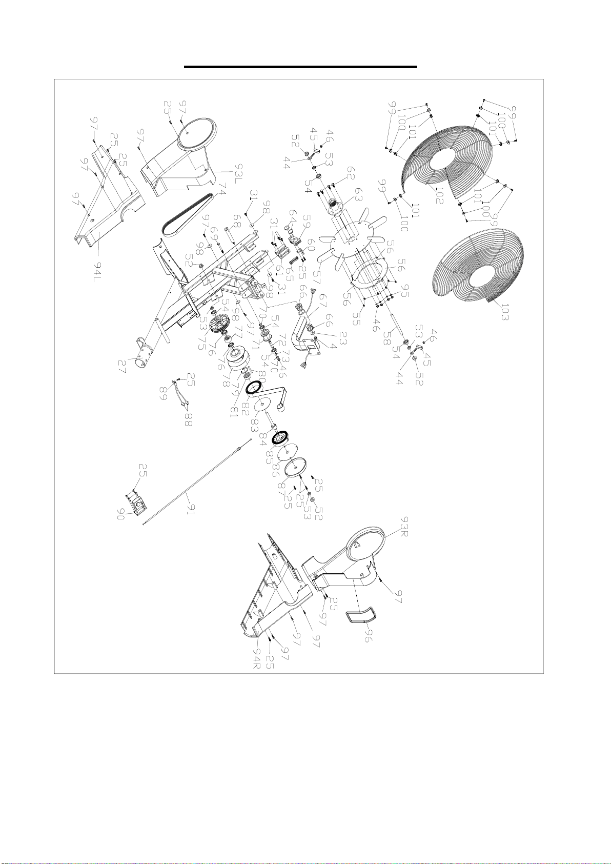
EXPLODED DIAGRAM 2

4
PARTS LIST
No.
Description
Spec.
Qty.
No.
Description
Spec.
Qty.
1
Inner Hex Pan Head
Bolt
M8*42*15*S6
2
35
Inner Hex Pan Head
Bolt
M6*16*Φ10
4
2
Transportation
Wheel
2
36
Upper Sliding Rail
Cover
1
3
Washer
d8*Φ16*1.5
16
37
Bottom Sliding Rail
Cover
1
4
Nylon Nut
M8*H7.5*S13
6
38
Rear Support
1
5
End Cap
Φ60.5*17
4
39
Bolt
M8*16*S14
4
6
Front Stabilizer
1
40
Seat
1
7
Nut
M8
4
41
U Baffle Plate
2
8
Adjustable Foot Pad
Φ52*18
4
42
Seat Support
2
9
Carriage Bolt
M8*73*20*H5
2
43
Bolt
M8*135*15*S1
4
3
10
Arc Washer
d8*Φ20*2*R30
8
44
Adjusting Bolt
M6*40*Φ10*2.5
4
11
Spring Washer
d8
16
45
Adjusting U Seat
4
12
Nut
M8*H16*S13
2
46
Nylon Nut
M6*H6*S10
9
13
Cross Pan Head
Screw
M5*10
4
47
Spacer
d8*Φ15*4
6
14
End Cap
1
48
Bearing
608Z
10
15
Computer
1
49
Roller
Φ45*38*Φ22
4
15a
Computer Wire
1
50
Spacer
Φ14*Φ8.3*30
2
16
Extension Wire
1
51
Roller
Φ33*106*Φ22
1
17
Handlebar Seat
1
52
Flange Nut
M10*1*H9.5*S1
5
4
18
Screw
M5*10*Ф8.5
2
53
Hexagonal Thin Nut
M10*1*H5*S17
4
19
Foam Grip
2
54
Bearing
6000-2RS
5
20
End Cap
Φ32*17
2
55
Cross Pan Head
Screw
M5*8
6
21
Handlebar
1
56
Aluminum Sheet
3
22
Bolt
M8*20*S13
4
57
Fan Wheel
1
23
Washer
d8*Φ20*2
5
58
Fan Wheel Axle
1
24
Bolt
M8*20*S5
14
59
Magnetic Plate
1
25
Screw
ST4.2*16*Φ8
21
60
L Sheet Metal
1
26L/R
Sliding Rail Cover
2
61
Magnetic Plate Seat
1
27
Main Frame
1
62
Hex Bolt
M6*16*S10
4
28L/R
Pedal Strap
2
63
Fan Wheel Axle
Sleeve
1
29L/R
Pedal
2
64
Round Magnet
Φ24*5
2
30
Pedal Seat
1
65
Spring
Φ1.2*Φ15*48*N
9
1
31
Cross Pan Head
Screw
M5*10*Φ8
10
66
Bushing
Φ32*3.3*Φ28*1
6*Φ14
2
32
Aluminum Sliding
Rail
Rail
2
67
Computer Support
1
33
Sliding Rail
1
68
Bolt
Φ14*81.5*M8*S
6
1
34
Limiter
Φ27*Φ23*16*Φ
6
4
69
Bolt
M6*55*15*S10
1

5
No.
Description
Spec.
Qty.
No.
Description
Spec.
Qty.
70
Circlip for Shaft
2
90
Motor
1
71
Pulley
Φ45*35
1
91
Tension Wire
1
72
Belt Wheel Shaft
1
92
Adapter
1
73
Washer
D10
1
93L/R
Front Cover
2
74
Belt
6PJ290
1
94L/R
Rear Cover
2
75
Belt Wheel
Φ112*61.5
1
95
Spring Washer
d6
4
76
Bearing
16003-2RS
2
96
Rubber Ring
1
77
Bearing
Φ35*d17*16
1
97
Screw
ST4.2*16*Φ8
12
78
Mesh Belt Wheel
1
98
Washer
d5*Φ16*1.5
4
79
Circlip
d35
1
99
Cross Pan Head
Screw
M4*10*Φ8
7
80
Fixing Axle for Mesh
Belt
1
100
Chuck for Steel Net
Cover
7
81
Bearing
6300-2RS
1
101
Chuck for Steel Net
Cover
7
82
Mesh Belt
1
102
Left Steel Net Cover
1
83
PC Board for Mesh
Belt Wheel
1
103
Right Steel Net Cover
1
84
Axle for Mesh Belt
Wheel
1
104
Rubber Ring
2
85
Volute Spring
1
105
Device Holder
1
86
Outer PC Board
1
106
Shipping Tube
1
87
Outer Cover for
Mesh Belt Wheel
1
A
Allen Wrench
S5
1
88
Sensor Wire
2
B
Spanner
S13-14-15
1
89
Sensor Holder
1
6
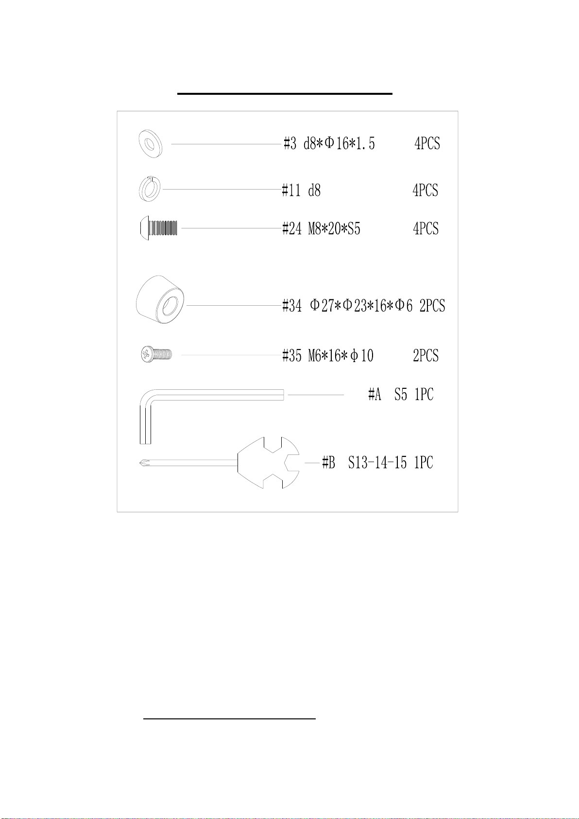
HARDWARE PACKAGE
Ordering Replacement Parts (U.S. and Canadian Customers only)
Please provide the following information in order for us to accurately identify the part(s) needed:
The model number (found on cover of manual)
The product name (found on cover of manual)
The part number found on the “EXPLODED DIAGRAM” and “PARTS LIST” (found near the
front of the manual)
Please contact us at [email protected] or 1- 877 - 90SUNNY (877-907-8669).
7
ASSEMBLY INSTRUCTIONS
We value your experience using Sunny Health and Fitness products. For assistance with parts or
(877-907-8669).
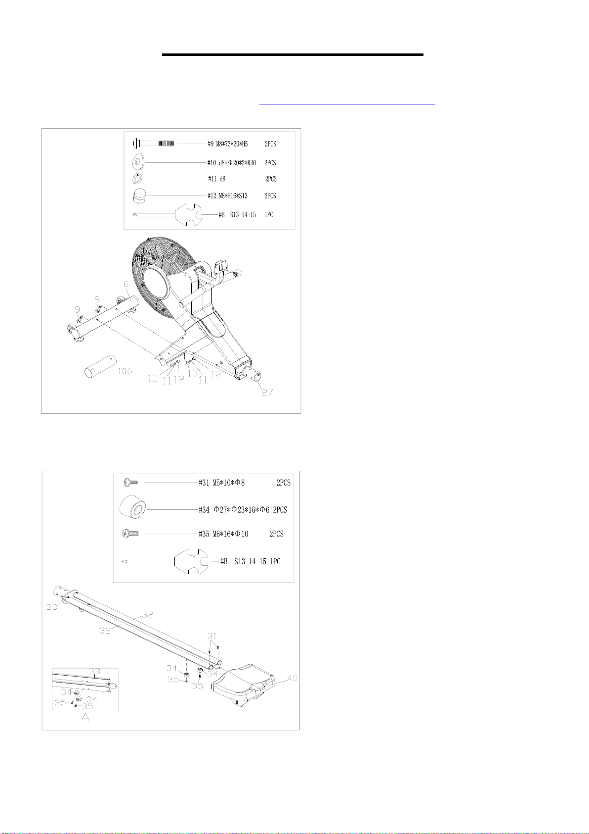
STEP 1:
Remove 2 Carriage Bolts (No. 9), 2
Arc Washers (No. 10), 2 Spring
Washers (No. 11), 2 Nuts (No. 12) and
Shipping Tube (No. 106) from the
Main Frame (No. 27) by Spanner (No.
B).
Attach the Front Stabilizer (No. 6) to
the Main Frame (No. 27) using 2
Carriage Bolts (No. 9), 2 Arc Washers
(No. 10), 2 Spring Washers (No. 11)
and 2 Nuts (No. 12) that were removed.
Tighten and secured with Spanner (No.
B).
You may save the Shipping Tube (No.
106) in case you’d like to repackage
and transport this rower in the future.
STEP 2:
Remove 2 Cross Pan Head Screws
(No. 31) from Sliding Rail (No. 33) by
Spanner (No. B);
Insert Seat (No. 40) into Sliding Rail
(No. 33);
Secure 2 Aluminum Sliding Rails (No.
32) to the Sliding Rail (No. 33) with 2
Cross Pan Head Screws (No. 31) that
were removed. Tighten with Spanner
(No. B);
Attach 2 Limiters (No. 34) to the
Sliding Rail (No. 33) using 2 Inner Hex
Pan Head Bolts (No. 35). Tighten and
secure with Spanner (No. B).
8
We value your experience using Sunny Health and Fitness products. For assistance with parts or
(877-907-8669).
36
37
25
3
11
24
3
11
24
24
11
3
33
38
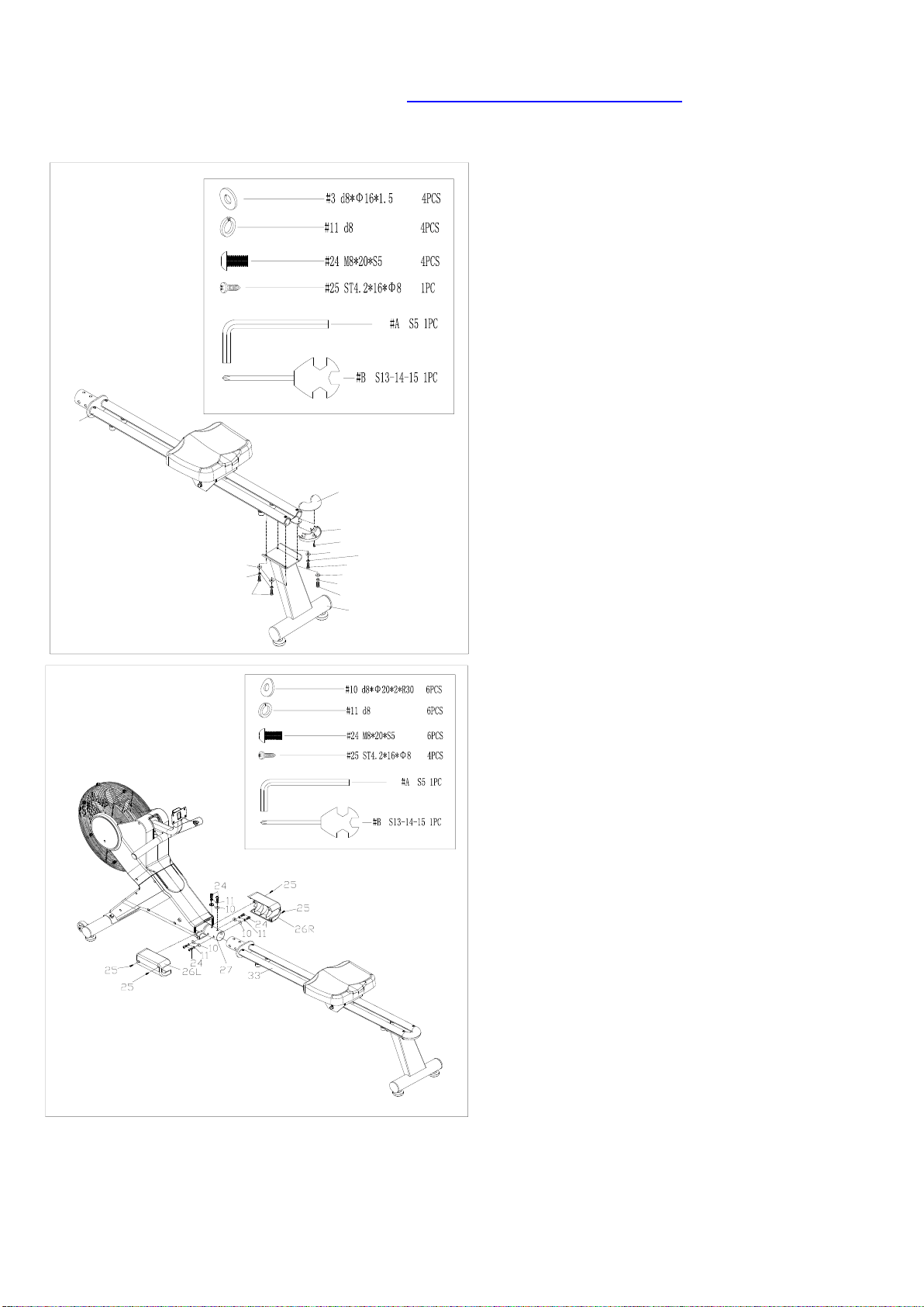
STEP 3:
Remove 1 Screw (No. 25) from Upper and
Bottom Sliding Rail Covers (No. 36 & No.
37) by Spanner (No. B).
Attach Upper and Bottom Sliding Rail
Covers (No. 36 & No. 37) to the Sliding
Rail (No. 33) with 1 Screw (No. 25) that
was removed. Tighten and secure with
Spanner (No. B);
Attach Rear Support (No. 38) to Sliding
Rail (No. 33) with 4 Washers (No. 3), 4
Spring Washers (No. 11) and 4 Bolts (No.
24). Tighten and secure with Allen Wrench
(No. A).
STEP 4:
Remove 6 Arc Washers (No. 10), 6
Spring Washers (No. 11) and 6 Bolts
(No. 24) from Main Frame (No. 27) by
Allen Wrench (No. A);
Remove the 4 Screws (No. 25) from the
Left & Right Sliding Rail Covers (No.
26L/R) and Main Frame (No. 27) with
Spanner (No. B);
Attach Sliding Rail (No. 33) to Main
Frame (No. 27) using 6 Arc Washers (No.
10), 6 Spring Washers (No. 11) and 6
Bolts (No. 24) that were removed. Tighten
and secure with Allen Wrench (No. A);
Attach the Left & Right Sliding Rail
Covers (No. 26L/R) to the Main Frame
(No. 27) using 4 Screws (No. 25) that
were removed. Tighten and secure with
Spanner (No. B).
9
We value your experience using Sunny Health and Fitness products. For assistance with parts or
(877-907-8669).
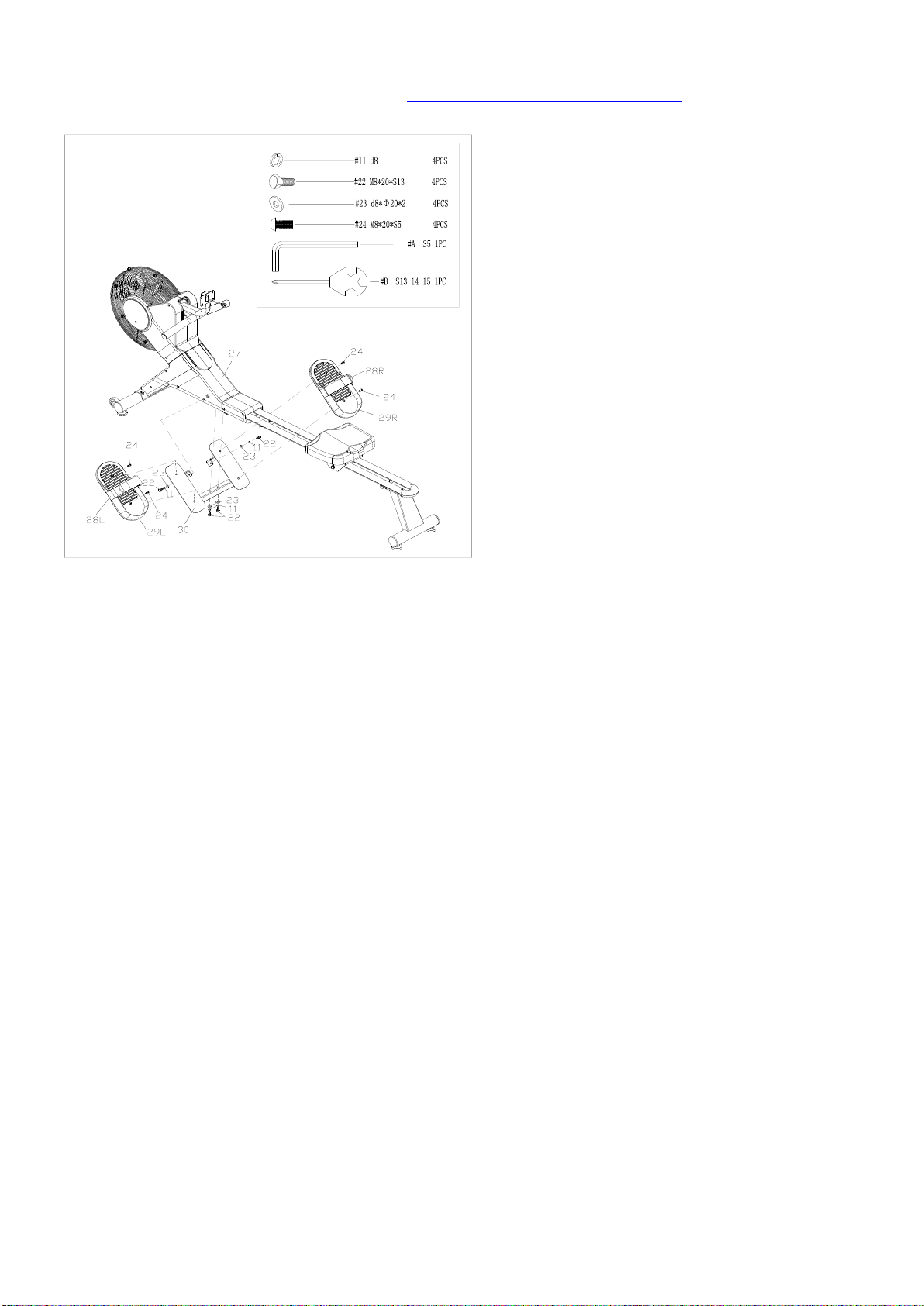
STEP 5:
Remove 4 Spring Washers (No. 11), 4
Bolts (No. 22) and 4 Washers (No. 23)
from Main Frame (No. 27) by Spanner
(No. B);
Attach Pedal Seat (No. 30) to Main
Frame (No. 27) using 4 Washers (No.
23), 4 Spring Washers (No. 11) and 4
Bolts (No. 22) that were removed.
Tighten and secure with Spanner (No.
B);
Remove 4 Bolts (No. 24) from Pedal
Seat (No. 30) with Allen Wrench (No.
A). Attach 2 Pedals (No. 29L/R) to the
Pedal Seat (No. 30) using 4 Bolts (No.
24) that were removed. Tighten and
secure with Allen Wrench (No. A);
Attention: The 2 Pedal Straps (No.
28L/R) should be put in the long groove
which is at the bottom of 2 Pedals (No.
29L/R). And don’t press the 2 Pedals
(No. 29L/R) against the 2 Pedal Straps
(No. 28L/R), so that the 2 Pedal Straps
(No. 28L/R) could be freely to pull up
and down.
10
We value your experience using Sunny Health and Fitness products. For assistance with parts or
(877-907-8669).
The assembly is complete!
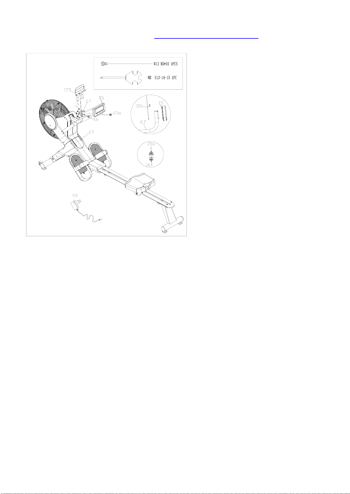
STEP 6:
Remove 4 Cross Pan Head Screws
(No. 13) from Computer (No. 15), then
pull out the Extension Wire (No. 16)
from Computer Support (No. 67), then
connect Extension Wire (No. 16) with
Computer Wire (No. 15a), and put
back these wires into the Computer
Support (No. 67);
Fix Device Holder (No. 105) and
Computer (No. 15) onto the Computer
Support (No. 67) with 4 Cross Pan
Head Screws (No. 13) that were
removed. Tighten and secure with
Spanner (No. B);
Insert the link wire of Adapter (No. 92)
to the adapter input hole on the front of
Main Frame (No. 27) and plug the
Adapter (No. 92) into an outlet.
Attention:Switch off the power when
not in use.
11
ADJUSTMENTS & USAGE GUIDE
6
2
38
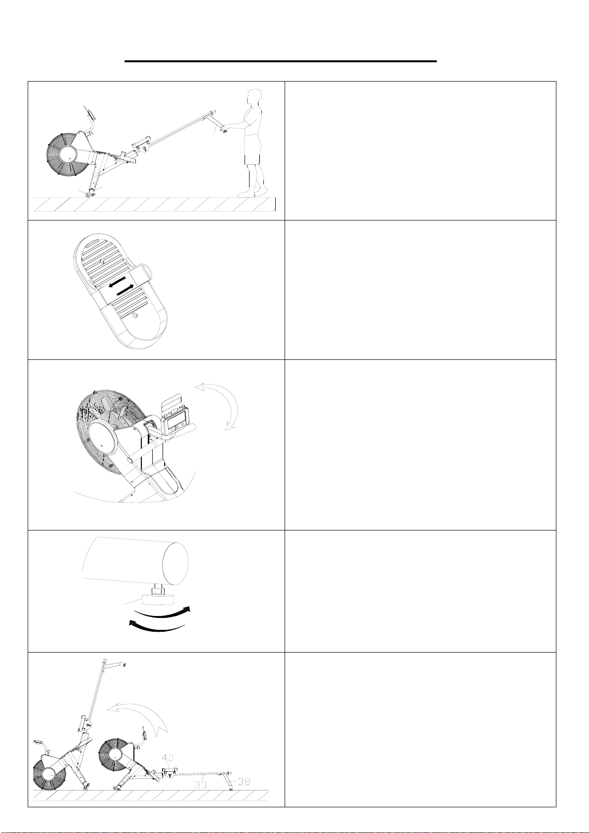
MOVING THE ROWER
To move the rower, lift up the Rear Support (No.
38) until the Transportation Wheels (No. 2) on
the Front Stabilizer (No. 6) touch the ground.
With the Transportation Wheels (No. 2) on the
ground, you can transport the rower to the desired
location with ease.
PEDAL ADJUSTMENT
The pedal strap is adjustable and can be
personalized to fit the user’s foot size.
COMPUTER ANGLE ADJUSTMENT
The rotation angle of computer support can be
adjusted to obtain the best view of the computer
LCD screen.
8
ADJUSTING THE BALANCE
When this product is on an uneven surface,
please adjust both Adjustable Foot Pads (No. 8)
according to the left instruction picture.
Figure A
Figure B
STORAGE
Attention!
Before you fold it up, please move the Seat (No.
40) to the front end of the Sliding Rail (No. 33).
(Figure B)
This rower is foldable design, you can lift it up to
save storage space. (Figure A)
12
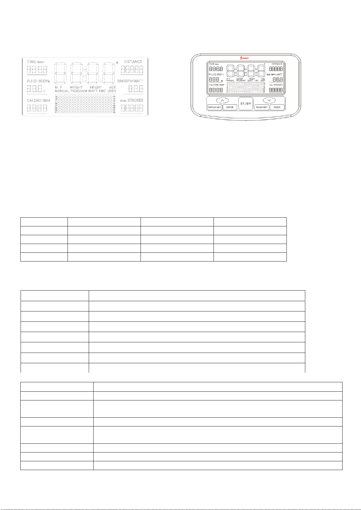
EXERCISE COMPUTER
DISPLAY INFORMATION
1. The main window displays the exercise status:
a. Scan mode: Display and switch among functions every 6 seconds: TIME (TIME/500m)
->DISTANCE->PLUSE->SPM (WATT)->CALORIE->STROKES (TOTAL STROKES);
b. Press “Display-ALT” to select and lock on any specific function.
2. TIME (TIME/500m), DISTANCE, PULSE, SPM (WATT), CALORIE, STROKES (TOTAL
STROKES) display window.
3. TIME (TIME/500m), SPM/WATT, STROKES/TOTAL STROKES display window.
Press “ENTER” to switch display TIME (TIME/500m), SPM (WATT), STROKES (TOTAL
STROKES) during use.
4. Resistance level : 16 levels.
SPECIFICATIONS
TIME.
0m:00s ~ 99m:59s
SPM
0 ~ 999 RPM
TIME/500m
0m:00s ~ 99m:59s
WATT
0~899 W
DISTANCE
0.0 ~ 99999 M
STROKES
0~9999
CALORIE
0 ~ 9999 KCAL
TOTAL STROKES
0~99999
PULSE
40-240 BPM
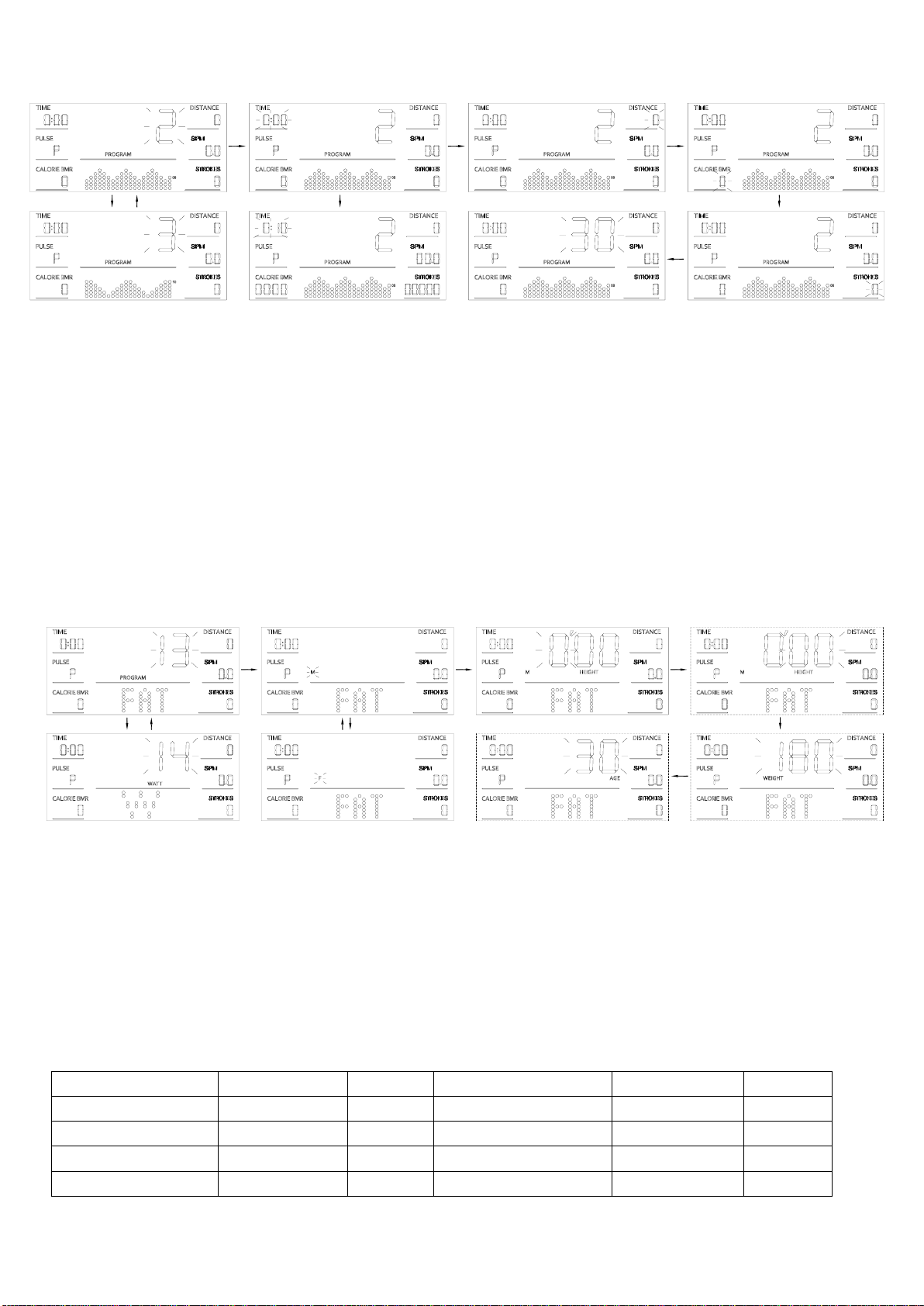
FUNCTION DESCRIPTION
MANUAL MODE
PRORGAM 1: The resistance value is adjusted manually.
PROGRAM MODE
PROGRAM 2~12 : The exercise is adjusted with preset value automatically.
BODY FAT
PROGRAM 13: Calculate body fat percentage, Body Mass Index (BMI) and
Basal Metabolic Rate (BMR).
WATT MODE
PROGRAM 14: The exercise is controlled by target watt.
H.R.C MODE
PROGRAM 15~18: The exercise is controlled by target heartbeat value
-65% ,75%,85%, user setting value.
USER MODE
PROGRAM19~22: The exercise is set by resistance value.
RECOVERY MODE
Based on the level of recovery heart rate.
WIRELESS PULSE
Wireless pulse receiver.
TIME
The time of each workout ,when starting exercise.
DISTANCE
The distances of each workout ,when starting exercise.
TIME/500m
The time of each 500 meters at the current pulp velocity.
PULSE
Heart beat .
CALORIE
The calorie burned of each workout, when starting exercise.
SPM
The strokes per minute, when starting exercise.
STROKES
The strokes of each workout, when staring exercise.
TOTAL STROKES
The total strokes of all workout.
13
KEY FUNCTION
UNIT
HEIGHT
WEIGHT
PULSE
CAL
DISTANCE
SPM
WATT
Ft ’in
LB
BPM
KCAL
M (Meter)
STROKES/ MIN
W
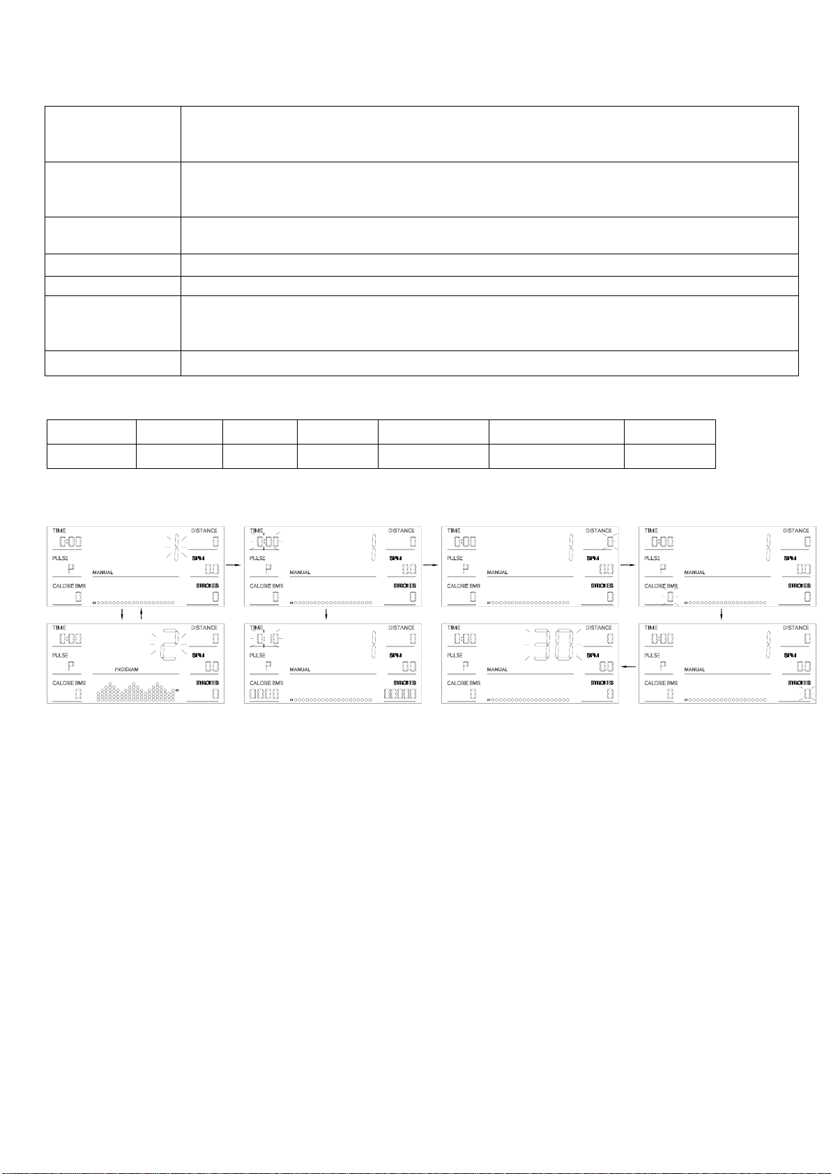
MANUAL MODE (PROGRAM 1)
1. Press “UP” or “DOWN” to select any functions;
2. Press “START/STOP” to start the exercise, or press “ENTER” to enter Setting Mode.
3. In Setting Mode, press “ENTER” to choose setting items with relevant flashing window for TIME,
DISTANCE, CALORIE, STROKES, AGE.
4. Press “UP” or “DOWN” to increase or decrease the value, and press “ENTER” to skip to next
item.
5. When all operations are complete, it will exit the Setting Mode automatically. Or press
“START/STOP” in the settings status to start.
6. Resistance level can be adjusted during use, with “UP” or “DOWN” button.
7. Once user begin the exercise, it will count down from the set value. When any of setting value
count to 0, it will beep and stop the workout automatically.
8. Press “START/STOP” to stop the exercise automatically at any point during use.
UP
.Move up the selections in PROGRAM Mode.
.Increase value in the Setting Mode.
.Increase resistance level during use.
DOWN
.Move down the selections in PROGRAM Mode.
.Decrease value in the Setting Mode.
.Decrease resistance level during use.
RESET
.Return to PROGRAM 1 from any status.
.Clear all values, except the user settings of U1-U4, WATT, PULSE.
START/STOP
.Start or stop the motion status.
RECOVERY
.To test the level of heart rate recovery.
ENTER
.To switch display SPM (WATT), STROKES (TOTAL STROKES) and TIME
(TIME/500M) during use.
.To choose function for setting.
Display-ALT
.Let you select and lock on to any function.
ENTER ENTER ENTER
ENTERUPUP
ENTER
DOWN
14
PROGRAM MODE (PROGRAM 2-12)
1. Press “UP” or “DOWN” to select any functions.
2. Press “START/STOP” to start the exercise, or press “ENTER” to enter Setting Mode.
3. In Setting Mode, press “ENTER” to choose setting items with relevant flashing window for TIME,
DISTANCE, CALORIE, STROKES, AGE.
4. Press “UP” or “DOWN” to increase or decrease the value, and press “ENTER” to skip to next
item.
5. When all operations are complete, it will exit the Setting Mode automatically. Or press
“START/STOP” in the settings status to start.
6. Resistance level is adjusted automatically during workout for each program, or press “UP” /
“DOWN” to make adjustment manually.
7. Once user begin the exercise, it will count down from the set value. When any of setting value
count to 0, it will beep and stop the workout automatically.
8. Press “START/STOP” to stop the exercise automatically at any point during use.
BODY FAT (PROGRAM 13)
1. Press “UP” or “DOWN” to select any functions;
2. Press “ENTER” to enter the Setting Mode.
3. In Setting Mode, press “ENTER” to choose setting items with relevant flashing window for
GENDER→HEIGHT(FOOT)→HEIGHT(INCH)→WEIGHT→AGE.
4. Press “UP” or ‘DOWN” to increase or decrease the value, and press “ENTER” to skip to next
item.
5. Press “START/STOP’ to start the test and hold the pulse sensors. Then the display will show
your body fat within 8 seconds.
6. You should keep your body relaxed to get the most accurate value.
B.M.I. (Body Mass Index)
Gender/Age
Underweight
Healthy
Slightly Overweight
Overweight
Obese
Male/ ≤ 30
< 14
14~20
20.1~25
25.1~35
> 35
Male/ > 30
< 17
17~23
23.1~28
28.1~38
> 38
Female/≤ 30
< 17
17~24
24.1~30
30.1~40
> 40
Female/ > 30
< 20
20~27
27.1~33
33.1~43
> 43
ENTER ENTER ENTER
ENTERUP
ENTER
UP
DOWN
ENTER
ENTER
UPUP
ENTER ENTER
DOWN
DOWN
ENTER
15
BODY FAT
Gender
Low
Medium
Slightly High
High
Male
<13%
13%-25.9%
26%-30%
>30%
Female
<23%
23%-35.9%
36%-40%
>40%
B.M.R (Basal Metabolic Rate)
The average number of calories burned per day for basic survival.
Ref:1300±100 (22-40years)
BODY TYPE:
B1
B2
B3
B4
B5
B6
B7
B8
B9
Severely
Underweight
Underweight
Thin
Slightly
Thin
Healthy
Slightly
Overweight
Overweight
Obese
Extremely
Obese
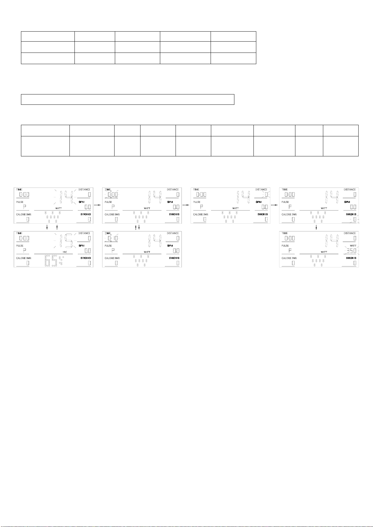
WATT MODE (PROGRAM 14)
1. Press “UP” or “DOWN” to select any functions;
2. Press “ENTER” to enter Setting Mode.
3. In Setting Mode, press “ENTER” to choose setting items with relevant flashing window for
TIME→DISTANCE→STROKES→WATT.
4. Press “UP” or “DOWN” to increase or decrease the value, and press “ENTER” to skip to next
item.
5. Press “START/STOP” to start.
6. Resistance level is adjusted automatically with WATT target value during workout.
7. Once user begin the exercise, it will count down from the set value. When any of setting value
count to 0, it will beep and stop the workout automatically.
8. Press “START/STOP” to stop the exercise automatically at any point during use.
Note: the WATT value is decided by the TORQUE and RPM. In this program, the watt value will
keep at constant value. It means that if you peddle quickly, the load resistance will decrease and if
you peddle slowly, the load resistance will increase to ensure you at the same watt value.
ENTER
UP
ENTER ENTER
UPDOWN
DOWN
ENTER
16
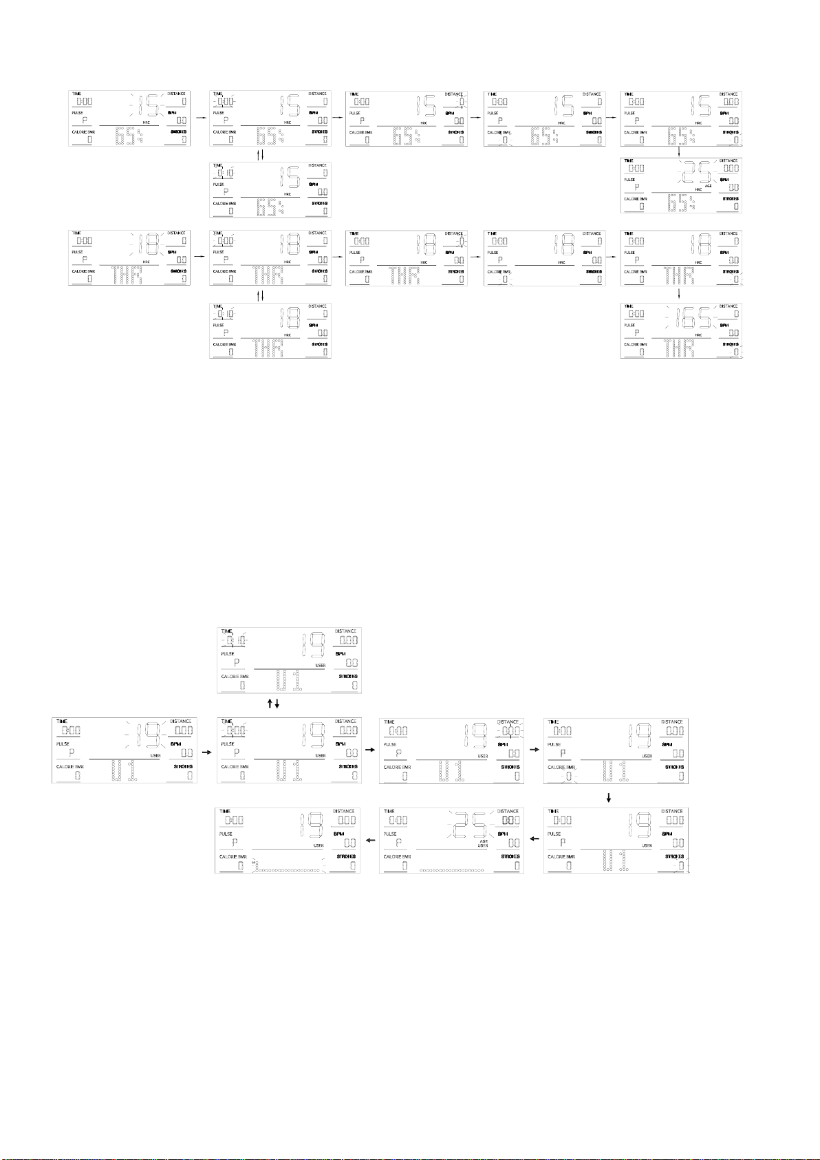
H. R.C MODE (PROGRAM 15-18)
1. Press “UP” or “DOWN” to select any functions.
2. Press “START/STOP” to start the exercise, or press “ENTER” to enter Setting Mode.
3. In Setting Mode, press “ENTER” to choose setting items with relevant flashing window for
TIME→DISTANCE→CALORIE→STROKES→AGE (only PROGRAM 15-17) → T.H.R(only
PROGRAM 18).
4. Press “UP” or “DOWN” to increase or decrease the value, and press “ENTER” to skip to next
item.
5. Press “START/STOP” to start.
6. Resistance level is adjusted automatically during workout with target T.H.R value.
7. Once user begin the exercise, it will count down from the set value. When any of setting value
count to 0, it will beep and stop the workout automatically.
9. Press “START/STOP” to stop the exercise automatically at any point during use.
NOTICE: you must hold the pulse sensors during exercise.
USER MODE (PROGRAM 19-22)
1. Press “UP” or “DOWN” to select U1-U4 mode.
2. Press “START/STOP” to start the exercise, or press “ENTER” to enter Setting Mode.
3. In Setting Mode, press “ENTER” to choose setting items with relevant flashing window for
TIME→DISTANCE→CALORIE→STROKIES→AGE →Resistance Value.
4. Press “UP” or “DOWN” to increase or decrease the value, and press “ENTER” to skip to next
item.
5. Press “START/STOP” to start.
6. Resistance level is adjusted automatically during workout in this program, or press “UP” /
“DOWN” to make adjustment manually.
7. Once user begin the exercise, it will count down from the set value. When any of setting value
count to 0, it will beep and stop the workout automatically.
8. Press “START/STOP” to stop the exercise automatically at any point during use.
ENTER
ENTER ENTER ENTER
ENTER ENTER ENTER
ENTER
UP
DOWN
ENTER
ENTER
UP
DOWN
ENTER
ENTER ENTER
UP
DOWN
ENTER
ENTERENTER

17
RECOVERY
TIMER 60"
RECOVERY MODE
During use, first test your pulse as above mentioned. Then press “RECOVERY” key to enter pulse
recovery function. The display will show 1 minute count-down as well as your pulse rate. Then, it
will pop up your pulse recovery level from F1 to F6, which is from the fastest recovery to slowest.
The fastest recovery F1 shows the best.
WIRELESS PULSE
The computer supports the standard 5.3Khz wearing heart rate detector.
1. Please wet the two electrodes of the heart rate detector.
2. Wear the heart rate detector on your chest.
FAULT CODE DESCRIPTION
FAULT CODE
POSSIBLE CAUSE
CHECK
SOLUTION
E1
The motor doesn't work.
Check if the motor wires are
plugged in or check if the
motor is stuck.
Plug in the motor wires
again or change the motor.
There is something
wrong with the wires.
Check if the wires are
damaged.
Change the wires or plug in
again.
The computer cannot
supply normal voltage to
the motor.
Test whether the voltage of
the motor is normal when
pressing UP and DOWN.
Change the computer.
E2
When starting the test in
the BODY FAT mode,
the heart rate detector
isn’t worn on your chest
immediately.
Please wear the heart rate
detector on your chest
within 3 seconds after the
test is started.
The computer cannot
display the heart rate
value.
Check if there is heart rate
value displayed in other
modes.
If there is no heart rate
value displayed in other
modes, replace the heart
rate detector.
If there is still no display,
replace the computer.
F1
BEST STATE
F2
WELL
F3
GOOD
F4
ORDINARY
F5
RELATIVELY POOR
F6
BAD

18
NOTE:
1. This computer uses a 9V/1A power adapter.
2. When the computer is abnormal, please pull out the power plug and re-insert.
3. Without any operation, the computer will enter standby mode after five minutes.
Version 1.2

19