0
PINK MAGNETIC ELLIPTICAL BIKE
P8300
USER MANUAL

1
IMPORTANT SAFETY INFORMATION
We thank you for choosing our product. To ensure your safety and health, please use this
equipment correctly. It is important to read this entire manual before assembling and using the
equipment. Safe and effective use can only be achieved if the equipment is assembled, maintained,
and used properly. It is your responsibility to ensure that all users of the equipment are informed of
all warnings and precautions.
1. Before starting any exercise program, you should consult your physician to determine if you
have any medical or physical conditions that could put your health and safety at risk or prevent
you from using the equipment properly. Your physician’s advice is essential if you are taking
medication that affects your heart rate, blood pressure, or cholesterol level.
2. Be aware of your body’s signals. Incorrect or excessive exercise can damage your health. Stop
exercising if you experience any of the following symptoms: pain, tightness in your chest,
irregular heartbeat, shortness of breath, lightheadedness, dizziness, or feelings of nausea. If
you do experience any of these conditions, you should consult your physician before continuing
with your exercise program.
3. Keep children and pets away from the equipment. The equipment is designed for adult use only.
4. Use the equipment on a solid, flat level surface with a protective cover for your floor or carpet.
To ensure safety, the equipment should have at least 2 feet (60 CM) of free space all around it.
5. Ensure that all nuts and bolts are securely tightened before using the equipment. The safety of
the equipment can only be maintained if it is regularly examined for damage and/or wear and
tear.
6. Always use the equipment as indicated. If you find any defective components while assembling
or checking the equipment, or if you hear any unusual noises coming from the equipment during
exercise, discontinue use of the equipment immediately and do not use until the problem has
been rectified.
7. Wear suitable clothing while using the equipment. Avoid wearing loose clothing that may
become entangled in the equipment.
8. Do not place fingers or objects into the moving parts of the equipment.
9. The maximum weight capacity of this unit is 220 pounds (100 KG).
10. The equipment is not suitable for therapeutic use.
11. To avoid bodily injury and/or damage to the product or property, proper lifting and moving are
required.
12. Your product is intended for use in cool and dry conditions. You should avoid storage in extreme
cold, hot or damp areas as this may lead to corrosion and other related problems.
13. This equipment is designed for indoor and home use only; it is not intended for commercial use.
2
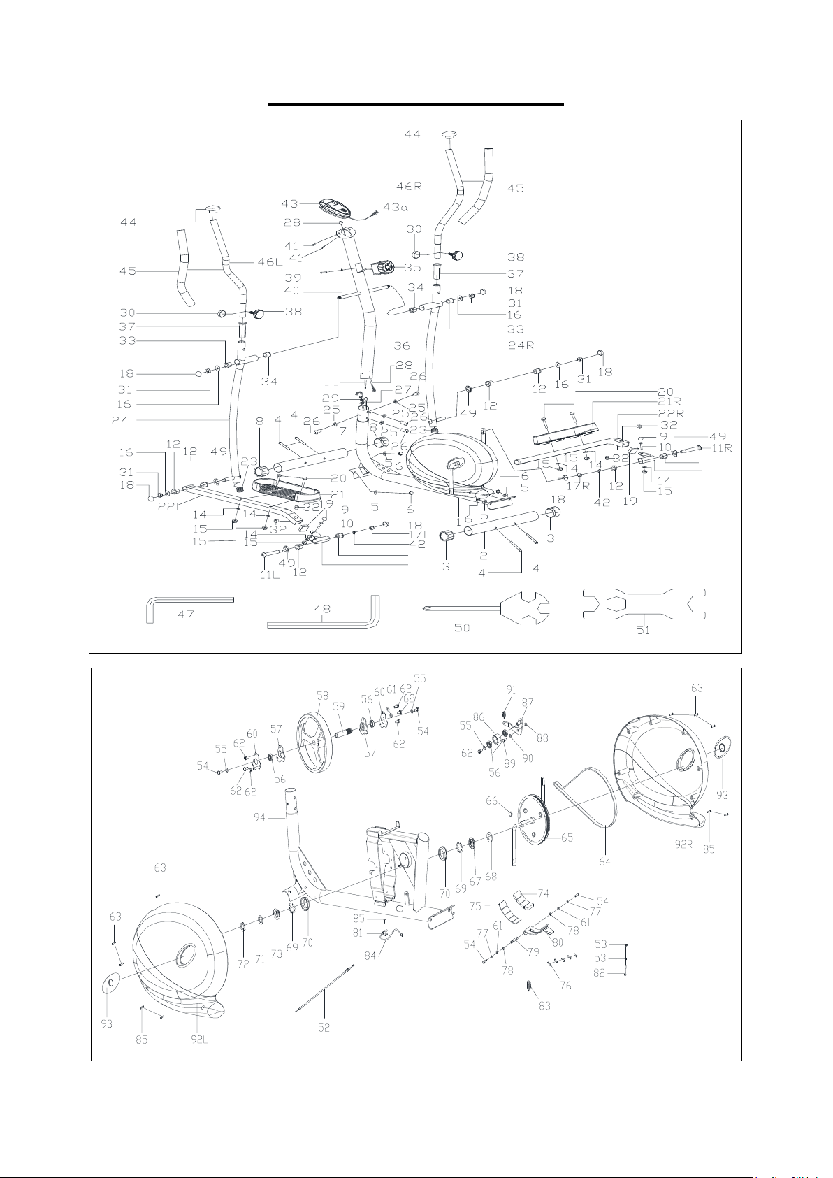
EXPLODED DIAGRAM
13L
13R
12
12
35a

3
PARTS LIST
No.
Description
Spec.
Qty.
No.
Description
Spec.
Qty.
1
Main Frame
1
32
Alloy Bushing
Φ14*Φ10.1*10
4
2
Rear Stabilizer
Φ50
1
33
Bushing
Φ28.5*Φ15.5*23
2
3
Adjust Adjustable End Cap
Φ50
2
34
Bushing with
Chamfer
Φ28.5*Φ15.5*23
2
4
Carriage Bolt
M10*60
4
35
Tension Control
Knob
8-level
1
5
Arc Washer
d10*Φ25*2*R30
4
35a
Tension Control
Wire
1
6
Nut
M10
4
36
Handlebar Post
1
7
Front Stabilizer
Φ50 w/ wheel
1
37
Bushing
Φ32*1.5
2
8
End Cap
Φ50 wheel
2
38
Knob
M8*36
2
9
Ball Cap
S16
2
39
Screw
M5*20
1
10
Bolt
M10*50
2
40
Arc Washer
d5*Φ20*1.5
1
11L/R
Hinge Bolt L/R
2
41
Screw
M5*10
2
12
Alloy Bushing
Φ24*Φ16.1*20
8
42
Spring Washer
d13
2
13L/R
Link Connector
Combination L/R
2
43
Computer
1
14
Washer
d10*Φ20*2
6
43a
Computer Wire
1
15
Nylon Nut
M10
6
44
End Cap
Φ28*1.5
2
16
Washer
d13*Φ26*2
4
45
Foam Grip
2
17L/R
Nylon Nut L/R
B0.5
2
46L/R
Handlebar L/R
2
18
Ball Cap
S18
6
47
Allen Wrench
S6
1
19
End Cap
J40*25*1.5
2
48
Allen Wrench
S8
1
20
Bolt
M10*45
4
49
Wave Washer
d17*Φ25* 0.3
4
21L/R
Pedal L/R
2
50
Spanner
S13-14-15
1
22L/R
Connecting Rod L/R
2
51
Spanner
S17-19
1
23
End Cap
Φ32*1.5
2
52
Tension Control
Wire
1
24L/R
Swing Rod L/R
2
53
Hex Nut
M6
2
25
Arc Washer
d8*Φ20*2*R30
4
54
Bolt
4
26
Screw
M8*16
4
55
Flat Washer
Φ6.5*Φ16*1.5
3
27
Sensor Wire
1
56
Bearing
6001RS C&U
4
28
Trunk Wire
1
57
Bearing Seat
D type
2
29
Tension Wire
1
58
External Magnetic
Flywheel
1
30
Ball Cap
S13
2
59
Inertia Wheel
1
31
Nylon Nut
R B0.5
4
60
Bearing Baffle
2

4
No.
Description
Spec.
Qty.
No.
Description
Spec.
Qty.
61
Flat Washer
Φ6*Φ12*1
4
78
Lock Washers for
Shaft
D12
2
62
Bolt
M6*9
7
79
Magnetic Board
Shaft
1
63
Screw
ST4.2*20
6
80
Magnetic Board
1
64
Belt
310PJ6
1
81
Needle Sensor
1
65
Pulley
1
82
Bolt
1
66
Round Magnet
1
83
Tension Spring 2
1
67
Three Slot Nut
1
84
Induction Line 1
1
68
Washer
1
85
Screw
ST4.2*16
5
69
Collar Ball
2
86
Inert Wheel
1
70
Collar Housing
2
87
Idler Connecting
Rod
1
71
Lock Washer
1
88
Plastic Nut
M8
1
72
Hex Nut
1
89
Tap Bolt
1
73
Two Slot Nut
1
90
Flat Washer
Φ10.5*Φ16*0.5
1
74
Black Magnet
4
91
Tension Spring 1
1
75
Magnet Positioning
Grid
1
92L
Left Cover
1
76
Screw
ST3*10
5
92R
Right Cover
1
77
Spring Washer
D6
2
93
Crank Plug
2
Ordering Replacement Parts (U.S. and Canadian Customers only)
Please provide the following information in order for us to accurately identify the part(s) needed:
✓ The model number (found on cover of manual)
✓ The product name (found on cover of manual)
✓ The part number found on the “EXPLODED DIAGRAM” and “PARTS LIST” (found near the front
of the manual)
Please contact us at [email protected] or 1- 877 - 90SUNNY (877-907-8669).
5
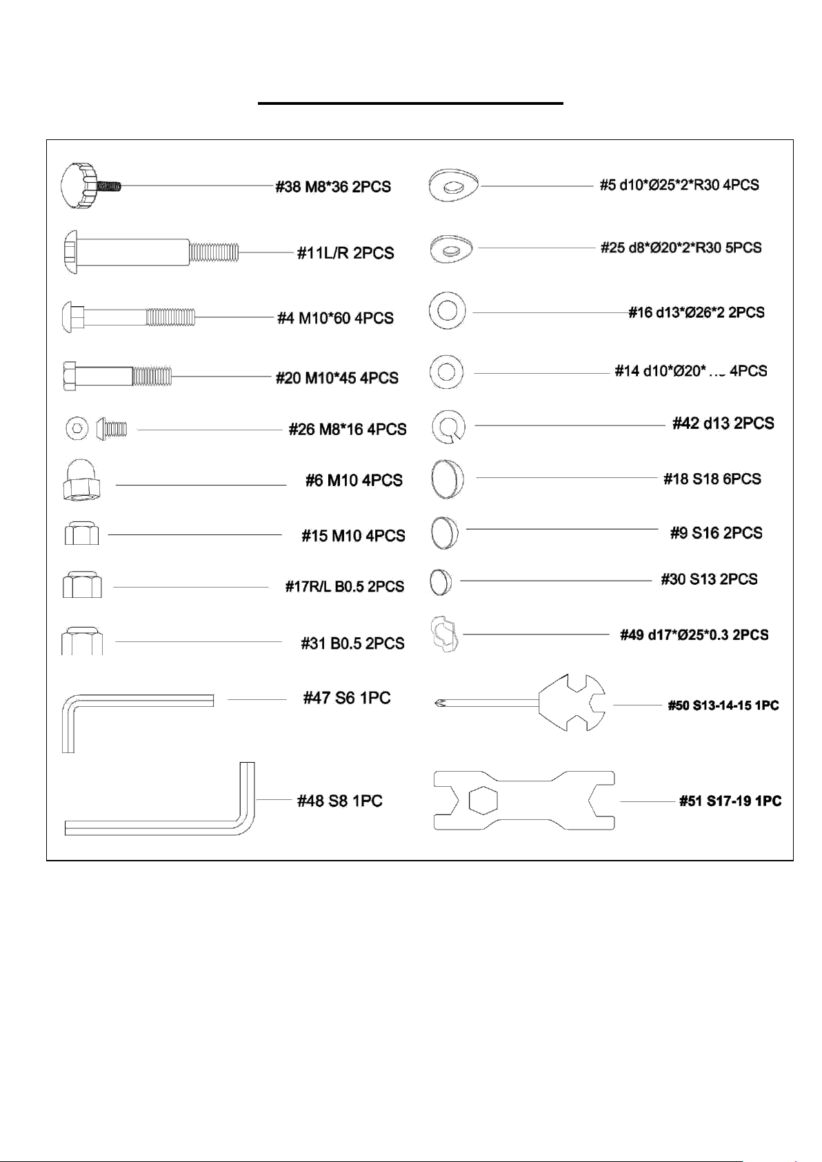
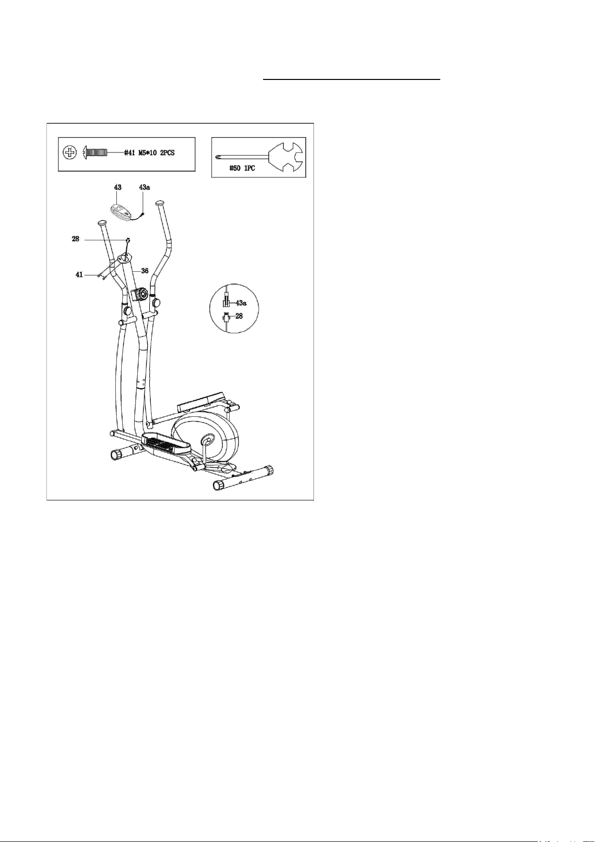
HARDWARE PACKAGE
2
6
ASSEMBLY INSTRUCTIONS
We value your experience using Sunny Health and Fitness products. For assistance with parts or
(877-907-8669).
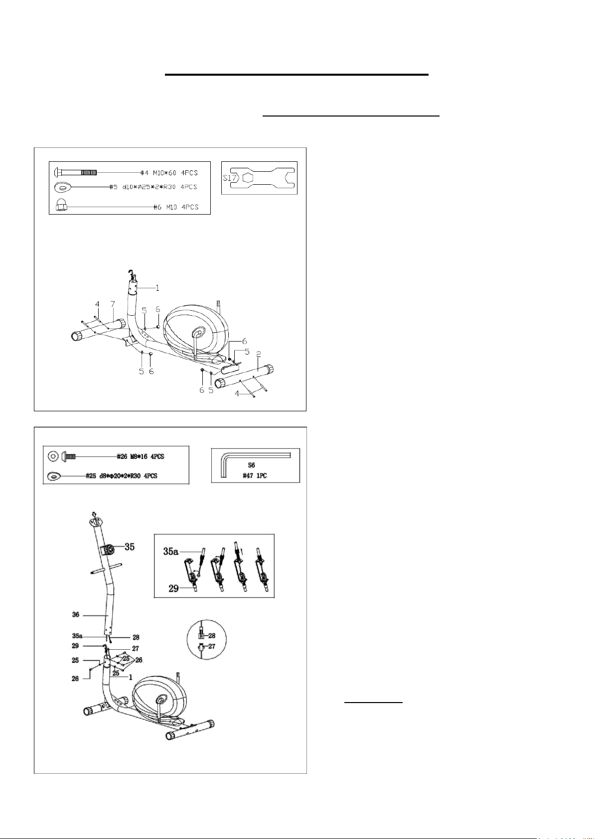
STEP 1:
Attach Front Stabilizer (No. 7) and
Rear Stabilizer (No. 2) to Main Frame
(No. 1) with 4 Carriage Bolts (No. 4), 4
Arc Washers (No. 5), and 4 Nuts (No.
6). Tighten and secure with Spanner
(No. 51).
STEP 2:
Note: Turn the Tension Control Knob
(No. 35) to the lowest resistance level
(level 1, all the way to the left) before
you connect the Tension Control Wire
(No. 35a)
Connect Trunk Wire (No. 28) to
Sensor Wire (No. 27). Then, connect
Tension Control Wire (No. 35a) with
Tension Wire (No. 29).
Attach Handlebar Post (No. 36) to
Main Frame (No. 1) with 4 Screws
(No. 26) and 4 Arc Washers (No. 25).
Tighten and secure with Allen Wrench
(No. 47).
CAUTION: Be careful not to pinch or
damage the wires during assembling.
7
We value your experience using Sunny Health and Fitness products. For assistance with parts or
(877-907-8669).
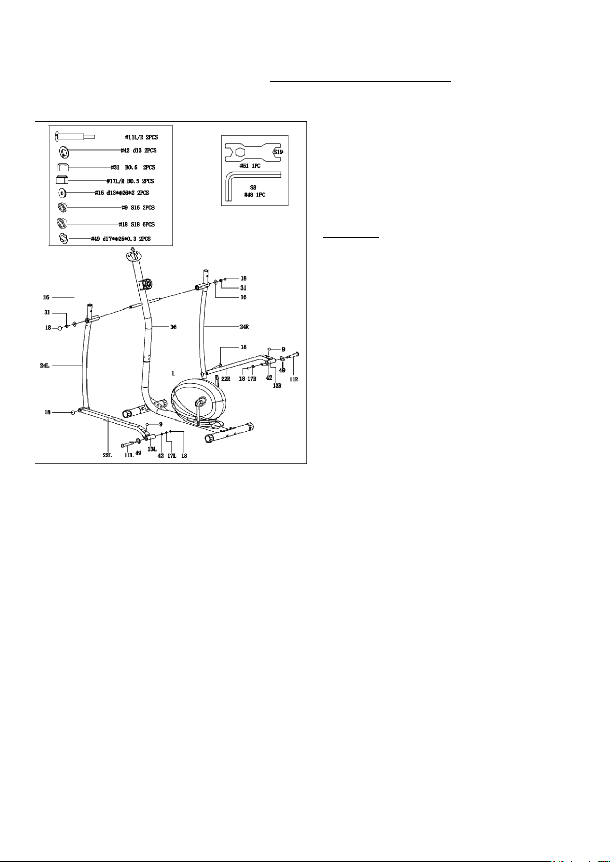
STEP 3:
Lock Swing Rods (No. 24L/R) to Handlebar
Post (No. 36) with 2 Nylon Nuts (No. 31) and
2 Washers (No. 16), then attach 2 Ball Caps
(No. 18).
CAUTION: Part 11 is labeled L for LEFT and
R for RIGHT. Please make sure you have the
correct bolt before installing.
Lock Connecting Rods (No. 22L/R) to the
cranks of Main Frame (No. 1) with 2 Hinge
Bolts (No. 11L/R), 2 Wave Washers (No. 49),
2 Spring Washers (No. 42), and 2 Nylon
Nuts (No. 17L/R). Tighten and secure with
Allen Wrench (No. 48) and Spanner (No.
51). Then, cover with 4 Ball Caps (No. 18)
and 2 Ball Caps (No. 9).
NOTE: Make sure to turn Left Hinge Bolt
(No. 11L) counter-clockwise, Right Hinge
Bolt (No. 11R) clockwise, Left Nylon Nut
(No. 17L) clockwise, and Right Nylon Nut
(No. 17R) counter-clockwise. Failure to
follow procedures may result in permanent
damage to your machine.
If you are having trouble with assembly of
Hinge Bolts (No. 11L/R), please see the next
page for alternate assembly method.
8
We value your experience using Sunny Health and Fitness products. For assistance with parts or
(877-907-8669).
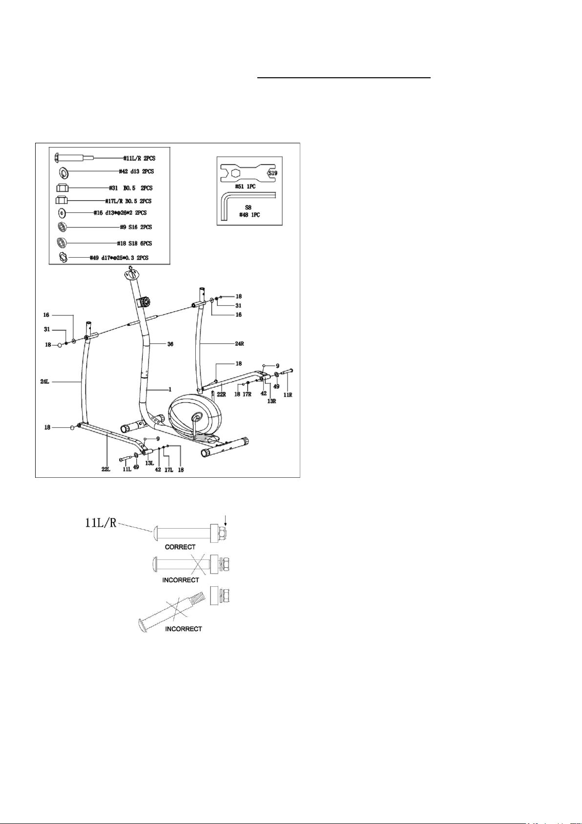
ALTERNATIVE INSTALLATION METHOD:
STEP 1:
Disconnect the Link Connector
Combinations (No. 13L/R) from the
Connecting Rods (No. 22L/R).
STEP 2:
Insert the 2 Hinge Bolts (No. 11L/R)
through the 2 Wave Washers (No. 49), then
through the hole of the Link Connector
Combinations (No. 13L/R). Screw the
Hinge Bolts (No. 11L/R) into the crank arm.
*Note: when assembling the left side, you
must screw counter-clockwise to tighten*
Connect the Spring Washers (No. 42) and
Nylon Nuts (No. 17L/R) and attach the Ball
Caps (No. 18). You can now reattach the
Link Connector Combinations (No.
13L/R) to the Connecting Rods (No.
22L/R).
IMPORTANT:
The Hinge Bolts (No. 11L/R) must be fully
inserted in the Link Connector
Combinations (No. 13L/R) and crank. This
will ensure the stability and durability of your
Elliptical.
NOTE:
In order to install the Hinge Bolts (No.
11L/R) properly, keep it perfectly straight as
the bolt goes through the pedal arms and
the crankshaft. If the hinge bolt is connected
to the crankshaft at an angle, damage to
both the hinge and the crankshaft may
occur.
9
We value your experience using Sunny Health and Fitness products. For assistance with parts or
(877-907-8669).
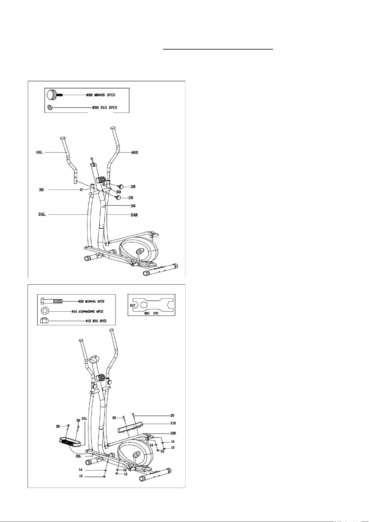
STEP 5:
Attach Pedals (No. 21L/R) to
Connecting Rods (No. 22L/R) with 4
Bolts (No. 20), 4 Washers (No. 14),
and 4 Nylon Nuts (No. 15). Tighten
and secure with Spanner (No. 51).
STEP 4:
Insert Handlebars (No. 46 L/R) into
Swing Rods (No. 24L/R). Tighten with 2
Knobs (No. 38), then cover with 2 Ball
Caps (No. 30).
10
We value your experience using Sunny Health and Fitness products. For assistance with parts or
(877-907-8669).
STEP 6:
Remove the preassembled 2 Screws
(No. 41) from Computer (No. 43).
Connect Trunk Wire (No. 28) to
Computer Wire (No. 43a).
Attach Computer (No. 43) to
computer holder on the top of
Handlebar Post (No. 36) with 2
Screws (No. 41) that were removed
from Computer (No. 43).
The assembly is complete!
11
ADJUSTMENTS & USAGE GUIDE
2
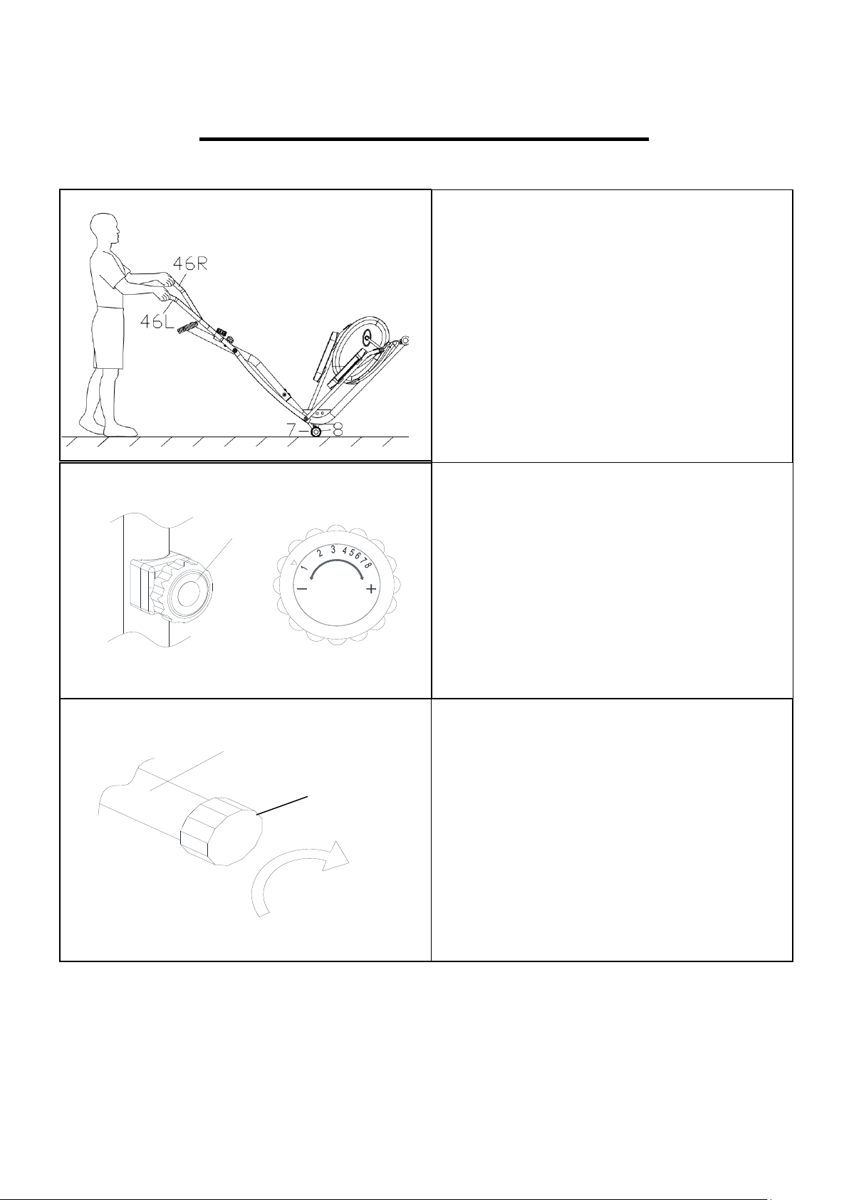
HOW TO MOVE THE ELLIPTICAL
The End Caps (No. 8) on the Front
Stabilizer (No. 7) are wheels. Hold the
Handlebars (No. 46L/R) and pull forward to
lift the rear of the elliptical off the floor. Now
you can move the elliptical.
ADJUSTING THE RESISTANCE
Adjust the resistance of the elliptical using
the Tension Control (No. 35). Increase the
level of resistance by turning the tension
knob to the RIGHT (clockwise), decrease the
level of resistance by turning the tension
knob to the LEFT (counter-clockwise).
ADJUSTING THE HEIGHT AND BALANCE
In order to achieve a smooth and
comfortable ride, you must ensure that the
elliptical is stable. If you notice that the
elliptical is unbalanced during use, you
should adjust the Adjustable End Caps
(No. 3) located beneath the Rear Stabilizer
(No. 2). To do so, turn it clockwise.
LOW HIGH
35
3

12
EXERCISE COMPUTER
FUNCTION BUTTONS
MODE: Press to select functions.
Press and hold the MODE button for 3 seconds to reset time, distance, and calories.
SET: Press to set values of time, distance, and calories when not in scan mode.
RESET: Press to reset time, pulse, distance, and calories to zero when not in scan mode.
A. Press the MODE button to cycle through functions: time, distance, and
Calories to select desired function.
B. Use the SET button to set a value for time, distance, or calories. The value
of a function will be set on a countdown.
C. Press the MODE button once more, to save the function value you’ve created.
FUNCTIONS
SCAN: Press MODE button until “▼” appears at SCAN position (or until “SCAN” appears), the
computer will rotate through all 5 functions: Time, Speed, Distance, Calories, and Total Distance.
Each function will be displayed for 6 seconds.
TIME: Counts the total time of the exercise from start to finish.
SPEED: Displays the current speed.
DISTANCE (DIST): Counts the distance of an exercise from start to finish.
CALORIES (CAL): Counts the total calories burned during an exercise from start to finish.
TOTAL DISTANCE (ODO): Counts the total distance after installing the batteries.
AUTO ON/OFF & AUTO START/STOP: If the elliptical is put into motion, or any button is pressed,
the computer will turn on. After about 8 minutes without any signal, the power (computer) will turn
off automatically.
ALARM: The functions of time, distance, and calorie can be set to countdown. When the value goes to
zero, the computer will beep. Press MODE to select the function, then press SET to adjust the value.
SPECIFICATIONS
FUNCTION
Auto Scan
Every 6 seconds
Running Time
00:00 ~ 99:59 (Minute: Second)
Current Speed
The max pick-up signal is 999.9 MILE/H
Trip Distance
0.0 ~ 999.9 MILE
Calories
0 ~ 9999 Kcal
Total Distance
0 ~ 9999 MILE
Battery Type
2 pcs of SIZE- AAA
Operating Temperature
0℃ ~ +40℃ (32℉~ 104℉)
Storage Temperature
-10℃ ~ +60℃ (14℉~ 140℉)
13
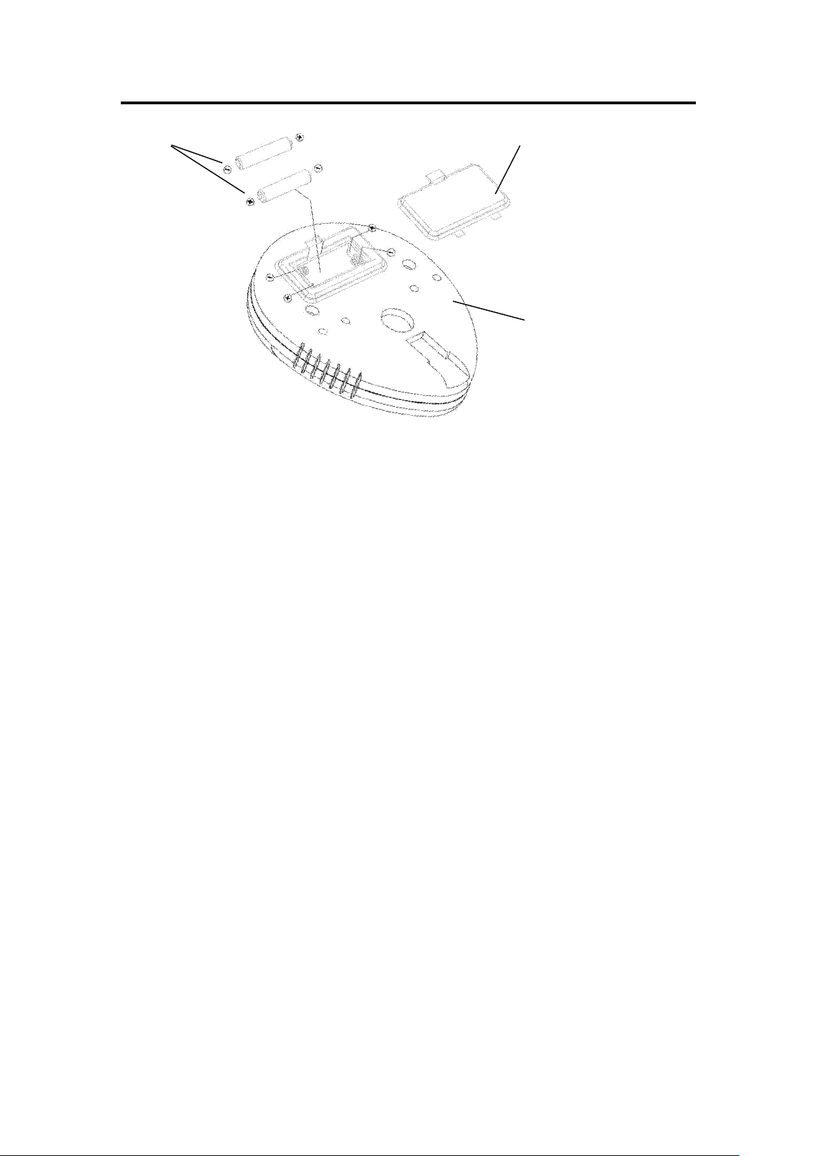
BATTERY INSTALLATION & REPLACEMENT
BATTERY INSTALLATION
1. Take out 2 AAA batteries from meter box.
2. Press the buckle of battery cover on the Computer (No. 43), then remove battery cover.
3. Install 2 AAA batteries into the battery case on the back of the Computer (No. 43). Pay attention
to the battery + and – poles before installing.
4. Press the buckle of battery cover, then put the battery cover back to the back of the Computer
(No. 43).
5. The installation is complete!
BATTERY REPLACEMENT
1. Press the buckle of battery cover on the back of the Computer (No. 43), then remove battery
cover.
2. Remove the 2 old AAA batteries in the battery case and install 2 new AAA batteries into the
battery case on the back of the Computer (No. 43). Pay attention to the battery + and – poles
before installing.
3. Press the buckle of battery cover, then put the battery cover back to the back of the Computer
(No. 43).
4. The replacement is complete!
BATTERY DISPOSAL
Dispose of the batteries according to the laws and regulations of your local region. Some batteries
may be recycled. When disposing or recycling, do not mix battery types.
Version 1.5
Battery
Battery Cover
43

14
