
1
IMPORTANT SAFETY INFORMATION
We thank you for choosing our product. To ensure your safety and health, please use this
equipment correctly. It is important to read this entire manual before assembling and using the
equipment. Safe and effective use can only be achieved if the equipment is assembled, maintained,
and used properly. It is your responsibility to ensure that all users of the equipment are informed of
all warnings and precautions.
1. Before starting any exercise program, you should consult your physician to determine if you
have any medical or physical conditions that could put your health and safety at risk or prevent
you from using the equipment properly. Your physician’s advice is essential if you are taking
medication that affects your heart rate, blood pressure, or cholesterol level.
2. Be aware of your body’s signals. Incorrect or excessive exercise can damage your health. Stop
exercising if you experience any of the following symptoms: pain, tightness in your chest,
irregular heartbeat, shortness of breath, lightheadedness, dizziness, or feelings of nausea. If
you do experience any of these conditions, you should consult your physician before continuing
with your exercise program.
3. Keep children and pets away from the equipment. The equipment is designed for adult use only.
4. Use the equipment on a solid, flat level surface with a protective cover for your floor or carpet.
To ensure safety, the equipment should have at least 2 feet (60 CM) of free space all around it.
5. Ensure that all nuts and bolts are securely tightened before using the equipment. The safety of
the equipment can only be maintained if it is regularly examined for damage and/or wear and
tear.
6. Always use the equipment as indicated. If you find any defective components while assembling
or checking the equipment, or if you hear any unusual noises coming from the equipment during
exercise, discontinue use of the equipment immediately and do not use until the problem has
been rectified.
7. Wear suitable clothing while using the equipment. Avoid wearing loose clothing that may
become entangled in the equipment.
8. Do not place fingers or objects into the moving parts of the equipment
9. The maximum weight capacity of this unit is 265 pounds (120 KG).
10. The equipment is not suitable for therapeutic use.
11. To avoid bodily injury and/ or damage to the product or property, proper lifting and moving are
required.
12. Your product is intended for use in cool, dry conditions. You should avoid storage in extreme
cold, hot, or damp areas as this may lead to corrosion and other related problems.
13. This equipment is designed for indoor and home use only! It is not intended for commercial use.
2
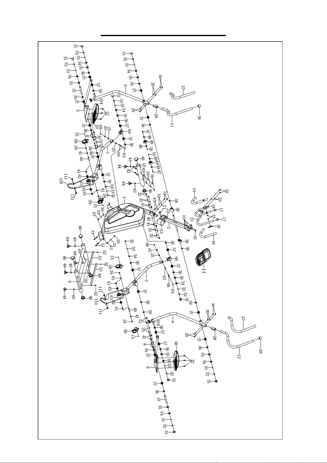
EXPLODED DIAGRAM 1
3
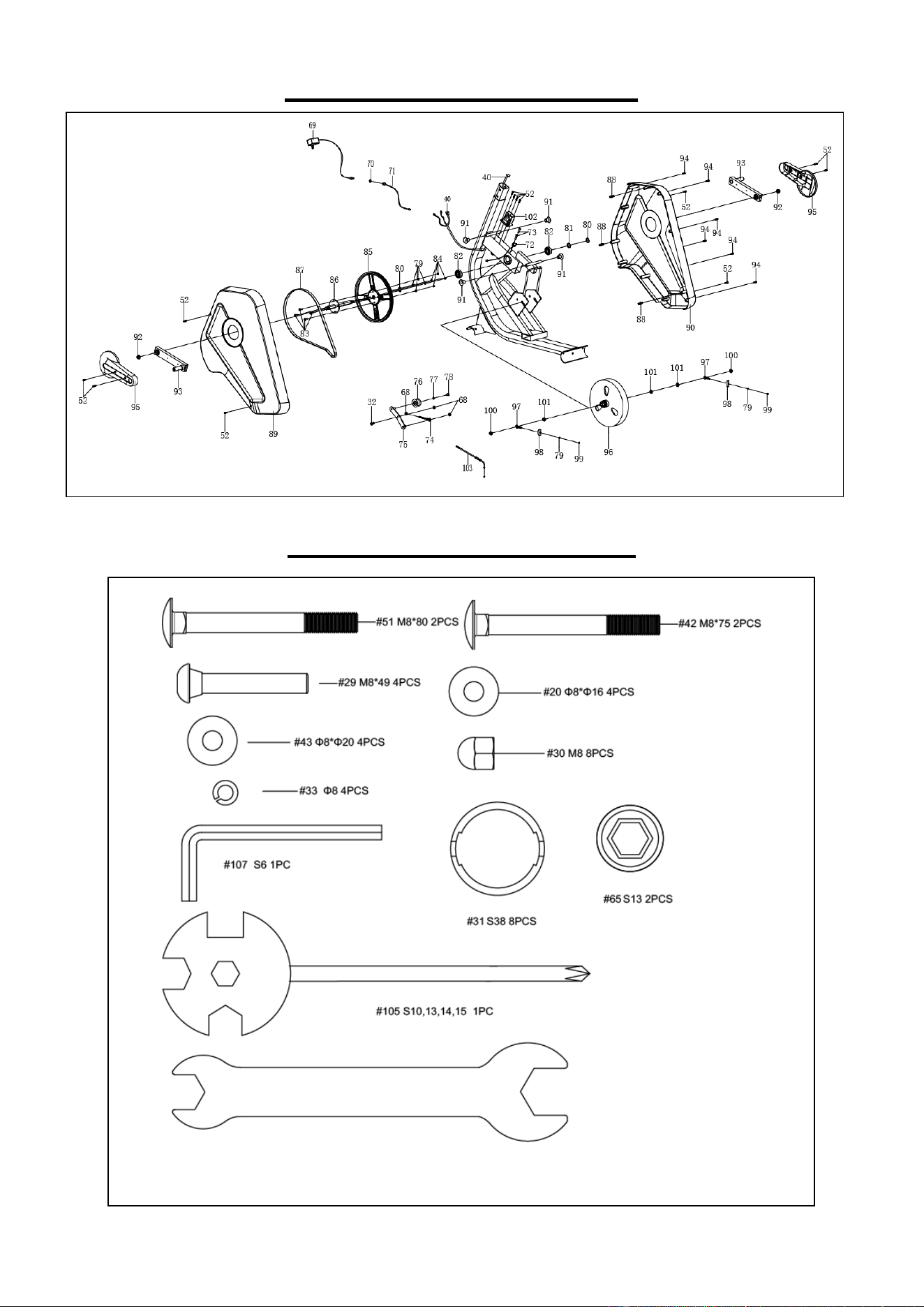
EXPLODED DIAGRAM 2
HARDWARE PACKAGE
#106 S14, 19 1PC

4
PARTS LIST
No. Description Spec. Qty
No. Description Spec. Qty
1 Main Frame
1
29 Bolt M8*49 4
2 Front Post
1
30 Cap Nut M8 8
3 Left Swing Tube
1
31 Cap Φ38 8
4 Right Swing Tube
1
32 Bolt M8*20 29
5
Left Foot Tube
1
33 Spring Washer Φ8
24
6 Right Foot Tube
1
34 Washer Φ8*Φ33*2.0 8
7
Drive Tube
2
35 Big Washer Φ19*Φ38*3.0
8
8
Foot Tube Connect
Patch
2
36 POM Bushing Ф27*11
20
9 Rear Main Frame
1
37 Plastic Bushing Φ38*24 20
10
Front Stabilizer
1
38 Wave Spring Washer Φ19*Φ26*0.3
4
11 Left Handrail Arm
1
39 Shaft Sleeve 2
12 Right Handrail Arm
1
40 Sensor Wire L=750mm 1
13 Handlebar
1
41 Big Washer Φ8*Φ20 8
14 Computer
1
42 Bolt M8*75 2
15 Screw M5*10
8
43 Big Wave Washer Φ8*Φ20
6
16
Handlebar Foam
Grip
Φ24*Φ31*450
2
44 Foot Pad M10*30
6
17
End Cap for
Handlebar
Φ25*1.5
2
45 Nut M10
6
18
Hand Pulse Sensor
Wire
L=750mm
2
46 Circular Tube Plug Φ60*1.5
6
19 Screw ST4.2*20 2
47 Bolt Φ8*32 2
20 Arc Washer Φ8*Φ16 6
48 Bearing 4
21
Extension Sensor
Wire
L=750mm
1
49 Roller Wheel Φ71*24
2
22 Bottle Holder-A
1
50 Bolt M6*12
2
23 Bottle Holder-B 1
51 Bolt M8*80 2
24 Bolt M8*16
4
52 Self- tapping Screw ST4.2*20
16
25
Connecting Rod
Small Bushing
Φ18*Φ8*10
4
53 Aluminum Bar 490*41*2.1
2
26
End Cap for
Handlebar
Φ50
2
54 Big Washer Φ8*Φ25*2.0
6
27
Handlebar Foam
Grip
Φ31*Φ37*700
2
55
Left Foot Pedal
1
28 Bushing
2
56
Right Foot Pedal
1

5
No. Description Spec. Qty
No. Description Spec. Qty
57 Connecting shaft Φ19* 174 2 85 Belt Pulley 1
58
Left Roller Cover
2
86
Straight Spindle
Assembly
1
59 Right Roller Cover 2 87 Belt 1
60
Roller Connecting
Shaft
2
88 Plastic Bolt Φ8*32
3
61 Roller Spacing 4 89 Left Chain Cover 1
62 Bearing 6202 4 90 Right Chain Cover 1
63 Pulley 2 91 Limit File Piece 4
64
Foot Turn Tube
Assembly
2
92 Nut M10*1.25
2
65 Cap S13 2 93 Crank 2
66 Bolt M6*50 2 94 Screw ST4.2*25 6
67 Washer Φ8*Φ16*1.5 2 95 Crank Cover Cap 2
68 Lock Nut M8 5 96 Flywheel 1
69 AC Adapter L=2000mm 1 97 Adjust Bolt M6*36 2
70 Hexagon Flat Nut S15 1 98 U-bracket 31*30*δ1.0 2
71 Power Supply Wire L=550mm 1 99 Bolt M6 S10 2
72 Sensor Wire L=500mm 1 100 Nut M10*1.0*6 2
73 Screw ST2.9*12 2 101 Nut M10*1 3
74 Adjust Bolt M8*65 1 102 Motor 1
75 Idle Wheel Bracket 1 103 Motor Tension Wire L=400mm 1
76 Press Wheel 1 104 Circular Tube Plug Φ38*1.8 2
77 Washer Φ12*Φ6*1.0 1 105 Spanner S10,13,14,15 1
78 Bolt M6*12 1 106 Spanner S14,19 1
79 Spring Washer Φ6 6 107 Allen Wrench S6 1
80 Circlip Φ20*1.0 2 108 Grease 1
81 Wave Washer Φ20*Φ24*0.3 1 109 PTFE Lubricant 1
82 Bearing 6004-2Z 2 110 Stopper 2
83 Bolt M6*15 4 111 Screw M4*8
8
84 Nut M6 4
Ordering Replacement Parts (U.S. and Canadian Customers only)
Please provide the following information in order for us to accurately identify the part(s) needed:
The model number (found on cover of manual)
The product name (found on cover of manual)
The part number found on the “EXPLODED DIAGRAM” and “PARTS LIST” (found near the front
of the manual)
Please contact us at support@sunnyhealthfitness.com or 1- 877 - 90SUNNY (877-907-8669).
6
ASSEMBLY INSTRUCTIONS
We value your experience using Sunny Health and Fitness products. For assistance with parts or
troubleshooting, please contact us at support@sunnyhealthfitness.com or 1-877-90SUNNY
(877-907-8669).
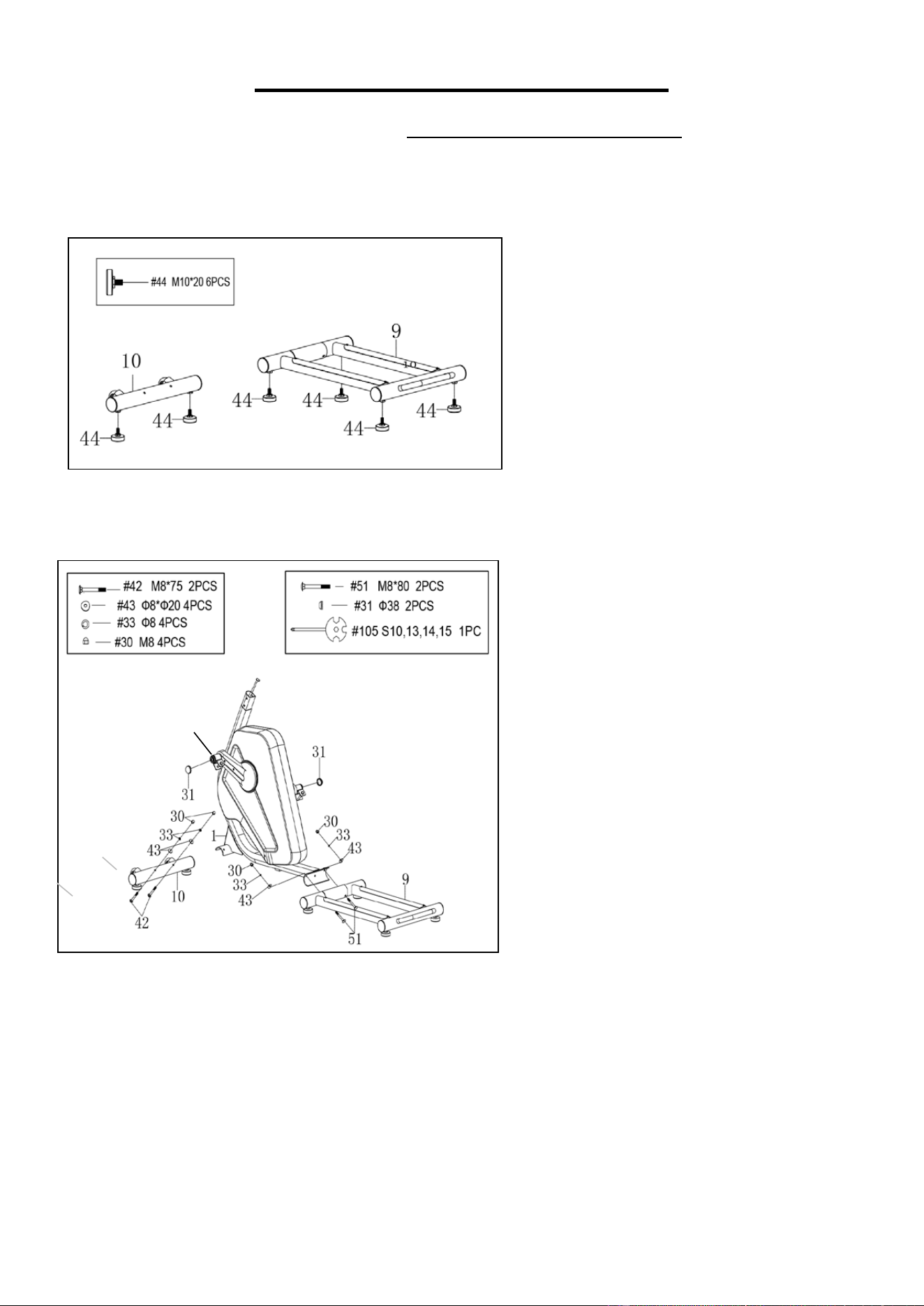
STEP 1:
Attach 4 Foot Pads (No. 44) onto the
Rear Main Frame (No. 9).
Attach 2 Foot Pads (No. 44) onto the
Front Stabilizer (No. 10).
STEP 2:
Attach the Rear Main Frame (No. 9)
onto the Main Frame (No. 1) with 2
Bolts (No. 51), 2 Big Wave Washers
(No. 43), 2 Spring Washers (No. 33),
and 2 Cap Nuts (No. 30). Tighten and
secure with Spanner (No. 105).
Attach the Front Stabilizer (No. 10)
onto the Main Frame (No. 1) with 2
Bolts (No. 42), 2 Big Wave Washers
(No. 43), 2 Spring Washers (No. 33),
and 2 Cap Nuts (No. 30). Tighten and
secure with Spanner (No. 105).
Use 2 Caps (No. 31) to cover both ends
of Cranks (No. 93).
93
7
We value your experience using Sunny Health and Fitness products. For assistance with parts or
troubleshooting, please contact us at support@sunnyhealthfitness.com or 1-877-90SUNNY
(877-907-8669).
STEP 4:
Remove 2 Bolts (No. 32), 2 Spring
Washers (No. 33), 2 Washers (No. 34),
and 2 Big Washers (No. 35) from the
Front Post (No. 2).
Note: Please lubricate the Front Post
(No. 2) with Grease (No. 108). Ensure
that the Left & Right Swing Tubes (No.
3 & No. 4) are in between the Cranks
(No. 93) and Front Post (No. 2) before
assembly.
Attach the Left & Right Swing Tube (No.
3 & No. 4) onto the Front Post (No. 2)
with 2 Bolts (No. 32), 2 Spring Washers
(No. 33), 2 Washers (No. 34), and 2 Big
Washers (No. 35) that were removed.
Tighten and secure with
Allen Wrench
(No. 107). Then cover with 2 Caps (No.
31).
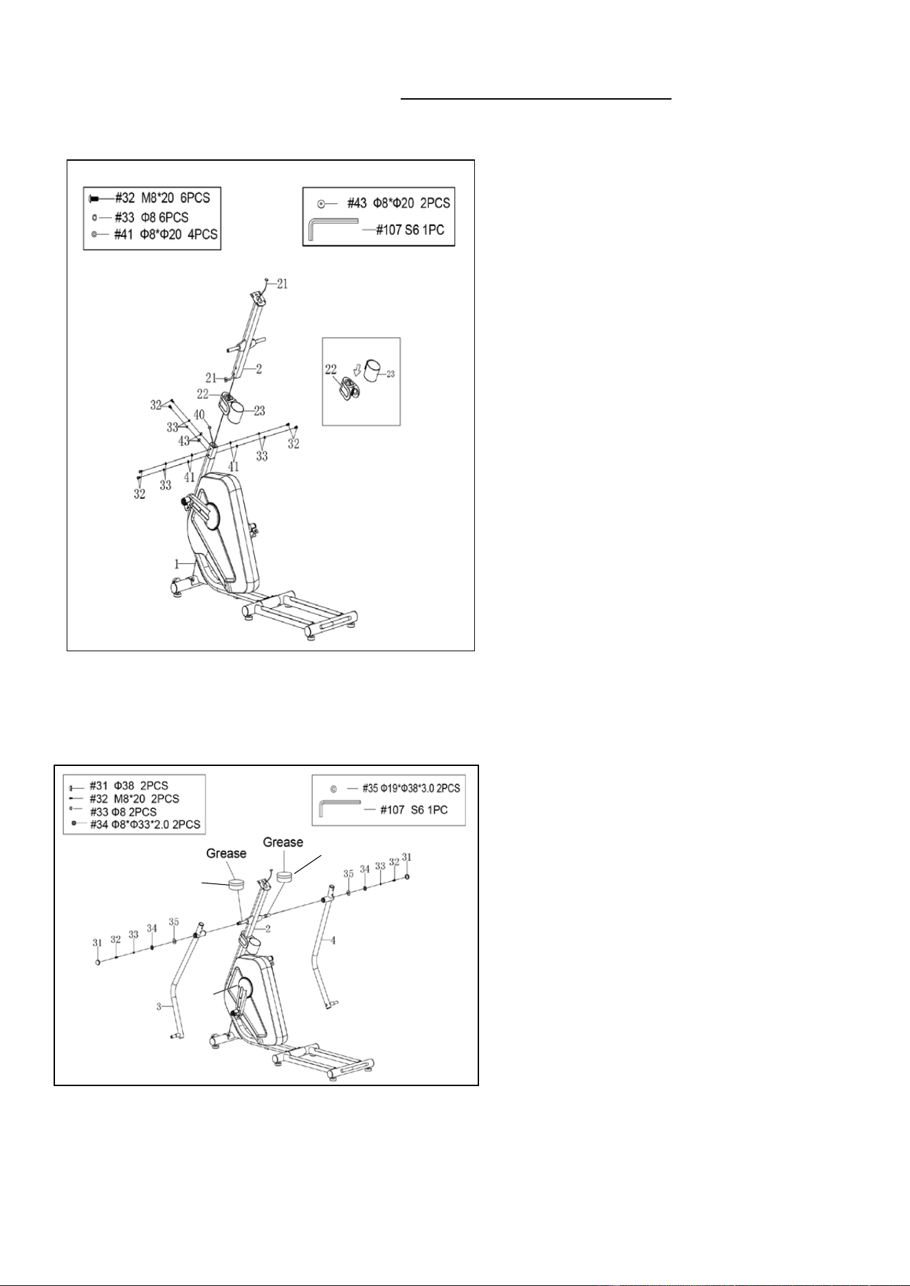
STEP 3:
Remove 6 Bolts (No. 32), 6 Spring
Washers (No. 33), 4 Big Washers (No.
41), and 2 Big Wave Washers (No. 43)
from the Main Frame (No. 1).
Attach Bottle Holder-B (No. 23) to Bottle
Holder-A (No. 22). Then slide them to the
tube of the Main Frame (No. 1).
Connect the Sensor Wire (No. 40) from
the Main Frame (No. 1) with the
Extension Sensor Wire (No. 21) from
the Front Post (No. 2).
Attach the Front Post (No. 2) onto the
Main Frame (No. 1) with 6 Bolts (No.
32), 6 Spring Washers (No. 33), 4 Big
Washers (No. 41), and 2
Big Wave
Washers (No. 43) that were removed.
Tighten and secure with Allen Wrench
(No. 107).
93
108
108
8
We value your experience using Sunny Health and Fitness products. For assistance with parts or
troubleshooting, please contact us at support@sunnyhealthfitness.com or 1-877-90SUNNY
(877-907-8669).
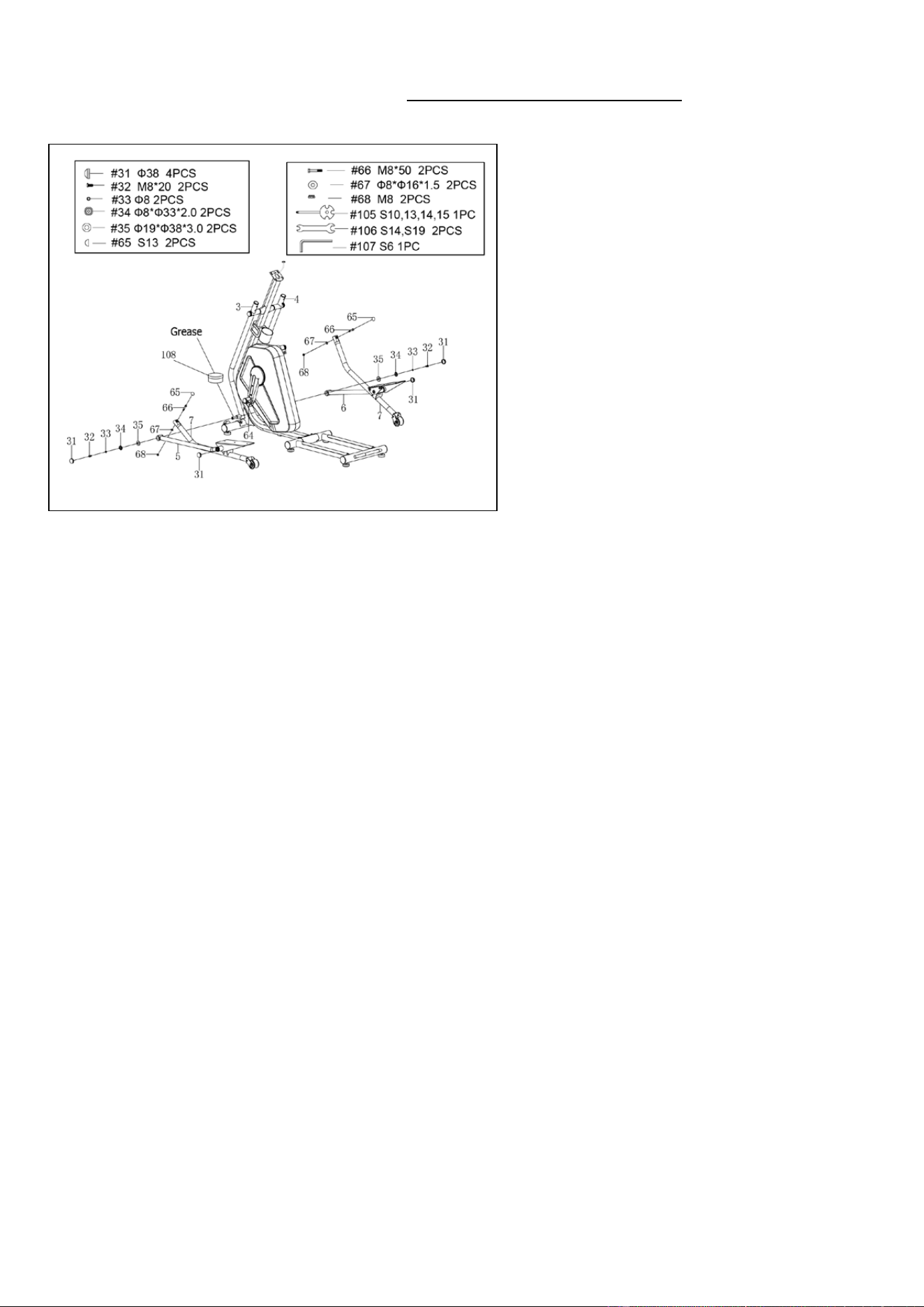
STEP 5:
Remove 2 Bolts (No. 32), 2 Spring
Washers (No. 33), 2 Washers (No. 34),
and 2 Big Washers (No. 35) from the
Left & Right Swing Tubes (No. 3 & No.
4).
Note: Please lubricate the Left & Right
Swing Tubes (No. 3 & No. 4) with
Grease (No. 108) before assembly.
Attach the Left & Right Foot Tubes
(No. 5 & No. 6) onto the Left & Right
Swing Tubes (No. 3 & No. 4) with 2
Bolts (No. 32), 2 Spring Washers (No.
33), 2 Washers (No. 34), and 2 Big
Washers (No. 35) that were removed.
Tighten and secure with Allen Wrench
(No. 107). Then cover the joints with 4
Caps (No. 31).
Remove 2 Bolts (No. 66), 2 Washers
(No. 67), and 2 Lock Nuts (No. 68)
from the Foot Turn Tube Assembly
(No. 64).
Attach the Drive Tubes (No. 7) on the
Foot Turn Tube Assembly (No. 64)
with 2 Bolts (No. 66), 2 Washers (No.
67), and 2 Lock Nuts (No. 68) that were
removed.
Tighten and secure with
Spanners (No. 105 & No. 106). Then
cover with 2 Caps (No. 65).
9
We value your experience using Sunny Health and Fitness products. For assistance with parts or
troubleshooting, please contact us at support@sunnyhealthfitness.com or 1-877-90SUNNY
(877-907-8669).
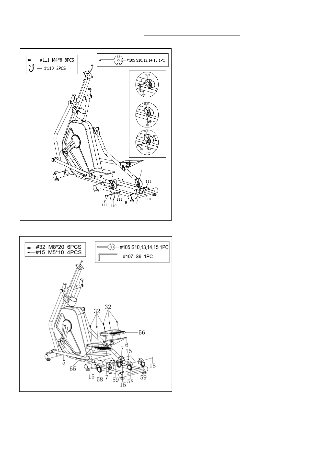
STEP 7:
Remove 4 Screws (No. 15) from the
Drive Tubes (No. 7).
Attach 2 sets of Left & Right Roller
Covers (No. 58 & No. 59) to 2 Drive
Tubes (No. 7) using 4 Screws (No. 15)
that were removed. Tighten and secure
with Spanner (No. 105).
Remove 6 Bolts (No. 32) from the plates
of Left & Right Foot Tubes (No. 5 & No.
6).
Attach the Left & Right Foot Pedals
(No. 55 & No. 56) onto the Left & Right
Foot Tubes (No. 5 & No. 6) using the 6
Bolts (No. 32) that were removed.
Tighten and secure with Allen Wrench
(No. 107).
STEP 6:
Remove 8 Screws (No. 111) and 2
Stoppers (No. 110) from the ends of 2
Drive Tubes (No. 7).
Hoop 2 Stoppers (No. 110) under and
around the rods of the Rear Main Frame
(No. 9). Then re-attach 2 Stoppers (No.
110) to the 2 Drive Tubes (No. 7) with 8
Screws (No. 111) that were removed.
Tighten and secure with Spanner (No.
105).
Note: Make sure that Drive Tubes (No.
7) can slide on the Rear Main Frame
(No. 09) smoothly and securely.
10
We value your experience using Sunny Health and Fitness products. For assistance with parts or
troubleshooting, please contact us at support@sunnyhealthfitness.com or 1-877-90SUNNY
(877-907-8669).
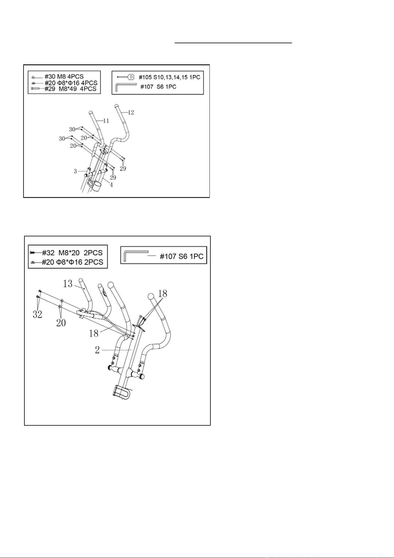
STEP 8:
Attach the Left Handrail Arm (No. 11)
onto the Left Swing Tube (No. 3) with
2 Bolts (No. 29), 2 Arc Washers (No.
20), and 2 Cap Nuts (No. 30). Tighten
and secure with Spanner (No. 105)
and Allen Wrench (No. 107).
Attach the Right Handrail Arm (No.
12) onto the Right Swing Tube (No. 4)
with 2 Bolts (No. 29), 2 Arc Washers
(No. 20), and 2 Cap Nuts (No. 30).
Tighten and secure with Spanner (No.
105) and Allen Wrench (No. 107).
STEP 9:
Remove 2 Bolts (No. 32) and 2 Arc
Washers (No. 20) from the Front Post
(No. 2).
Insert the
Hand Pulse Sensor Wire
(No. 18) into the opening on the side of
Front Post (No. 2) and pull it out from
the square opening on top of the Front
Post (No. 2).
Attach the Handlebar (No. 13) onto the
Front Post (No. 2) with 2 Bolts (No.
32) and 2 Arc Washers (No. 20) that
were removed. Tighten and secure with
Allen Wrench (No. 107).
11
We value your experience using Sunny Health and Fitness products. For assistance with parts or
troubleshooting, please contact us at support@sunnyhealthfitness.com or 1-877-90SUNNY
(877-907-8669).
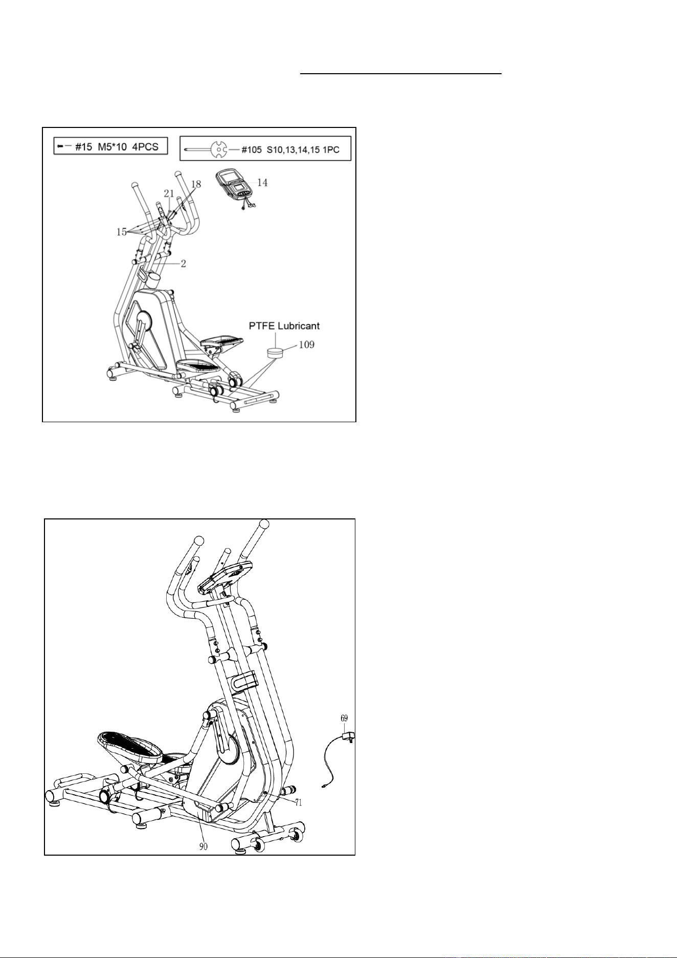
STEP 10:
Remove 4 Screws (No. 15) from the
back of the Computer (No. 14).
Connect the Extension
Sensor Wire
(No. 21) and Hand Pulse Sensor Wire
(No. 18) to the wires of Computer (No.
14). Then insert the wires into the Front
Post (No. 2).
Attach Computer (No. 14) onto the top
end of the Front Post (No. 2)
with 4
Screws (No. 15)
that were removed.
Tighten and secure with Spanner (No.
105).
Note: Please lubricate the Aluminum
Rod with the PTFE Lubricant (No. 109)
if you feel friction when exercising.
STEP 11:
Before plugging in the elliptical, check
the specifications on the AC Adapter
(No. 69) carefully and make sure the
power supply is compatible.
Plug one end of the AC Adapter (No.
69) into the power jack of the Power
Supply Wire (No. 71) on the back of
the Right Chain Cover (No. 90). Then
plug the other end of the AC Adapter
(No. 69) into the electrical wall outlet.
The assembly is complete!
12
ADJUSTMENTS GUIDE
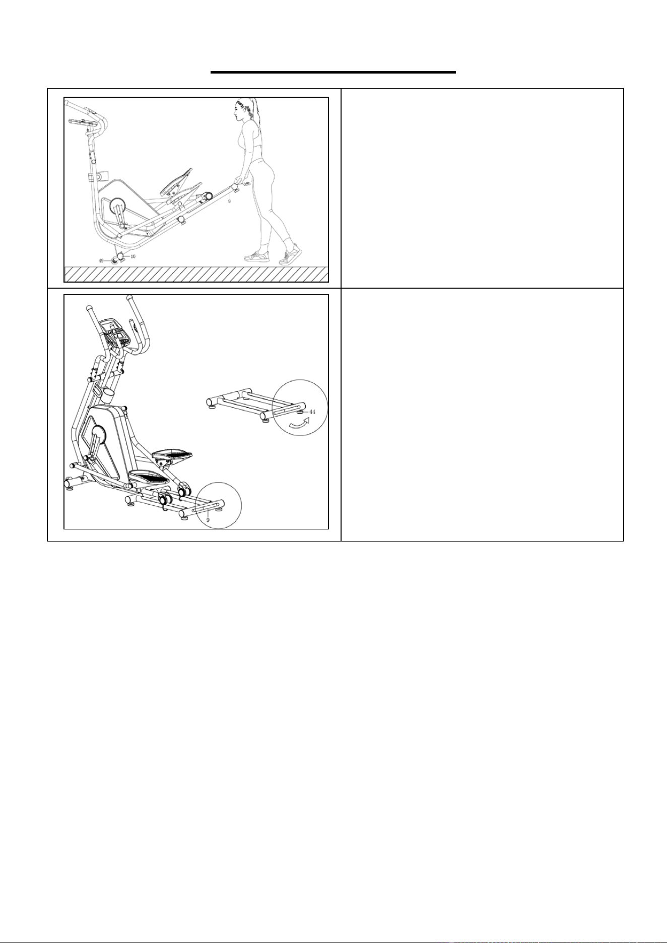
HOW TO MOVE THE ELLIPTICAL
Hold the Rear Main Frame (No. 9) and pull
upward to lift the rear of the elliptical off the
floor until the Roller Wheel (No. 49) on the
Front Stabilizer (No. 10) touch the
ground. Now you can move the elliptical
with ease.
ADJUSTING THE BALANCE
In order to achieve a smooth and
comfortable ride, you must ensure that the
elliptical is stable. If you notice that the
elliptical
is unbalanced during use, you
should adjust the Foot Pads (No. 44)
located underneath the Rear Main Frame
(No. 9). To do so, turn the Foot Pads (No.
44) clockwise.
13
IMPORTANT ELECTRICAL INFORMATION
WARNING: This elliptical trainer requires a power source of 1 amp (100-240V) in order to
properly operate. For your safety, as well as the safety of others, please verify that the power
source is correct before plugging in the equipment. Any power source above or below this level
could cause significant damage to the equipment and or user.
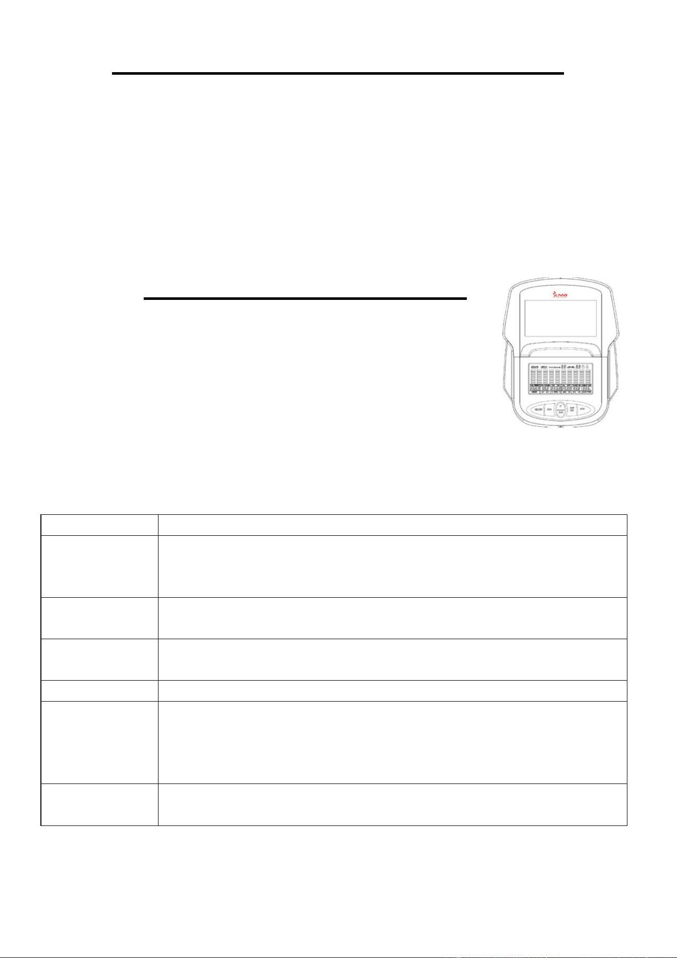
OPERATING INSTRUCTIONS
Plug the adaptor into the elliptical trainer and into the outlet.
The computer will turn on.
The computer will turn off if there is no activity for 4 minutes. Press
any key on the computer to turn it on again.
NOTE: You can still use the elliptical trainer when it is not plugged in. However, the
computer will not be working, and you cannot adjust the resistance level or use any of the functions.
KEY FUNCTIONS:
KEY
FUNCTION
START/STOP Start and pause workouts
Start body fat measurement
Hold for 3 seconds to reset all function values to zero
DOWN Lower the resistance level during workout.
Decrease value of selected parameter
UP
Increase the resistance level during workout.
Increase value of selected parameter
ENTER To input the value or mode
RECOVERY
Enter Recovery function when computer displays the heart rate value.
Recovery displays F1-F6
F1 is poor recovery heart rate
F6 is excellent recovery heart rate
MODE
During workout, switch display from RPM to SPEED, ODO to DIST and
WATT to CALORIES
WORKOUT SELECTION:
After turning the computer on by plugging in the adaptor or if already plugged in, pressing any
button on the computer, use the UP or DOWN button to make a selection. Then press ENTER
button to choose the desired mode.

14
There are 7 basic workout modes:
Manual, Pre- programs, Watt Program, Body Fat Program, Target Heart Rate Program, Heart Rate
Control Program, and User Program.
FUNCTIONS:
SPEED: Displays current training speed. Maximum speed is 99.9 MPH.
RPM: Displays current rotation per minute.
TIME: Accumulates the workout time from 00:00 to 99:59. Users can preset the target time they
want.
DIST: Accumulates the workout distance from 0.00 up to 999.9 miles. Users can preset the target
distance they want to reach.
ODO: Displays the total distance from 0 to 9999 miles.
CAL: Accumulates the calorie burned from 0 to 9999. Users can preset the target Calories they
want to burn.
WATT: Displays current watt.
HEART RATE: Displays the current heart rate in beats per minute.
TARGET HR.: Users can preset their Target Heart Rate.
PROGRAM: There are 24 different programs to choose for training.
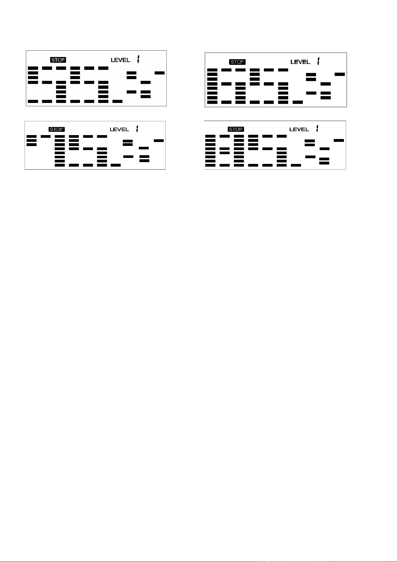
LEVEL: The program has 10 columns of bars and 8 bars in each column. Each column represents
a 1-minute workout and each bar represents 2 resistance levels.
WORKOUT PARAMETERS:
TIME / DISTANCE / CALORIES / AGE / WATT / TARGET HEART RATE
Setting Workout Parameters
After selecting the desired workout mode: Manual Program, Pre-set Programs, Watt Control
Program, Body Fat Program, Target Heart Rate Program, Heart Rate Control Program, and User
Program. You may pre-set several workout parameters for desired results.
Note: Some parameters are not adjustable in certain programs. Time and Distance cannot
be set up at the same time.
Once a program has been selected, press ENTER and Time will flash.
Using the UP or DOWN buttons, you may select the desired time value. Press ENTER to input the
values. The flashing prompt will move to the next parameter. Continue using the UP or DOWN
button. Press the START/STOP button to begin the workout.
15
More About Workout Parameters
Field Setting Range
Default
Value
Increment/
Decrement
Description
Time
0:00~99:00 00:00 ±1:00
1.When display is set as 0:00, Time will
count up.
2.When Time is set as 1:00-99:00, it will
count down to 0.
Distance
0.00~999.0 0.00 ±1.0
1.When display is set as 0.0, Distance
will count up.
2.When Distance is set as 1.0~999.0, it
will count down to 0.
Calories 0~9995 0 ±5
1.When display is set as 0, Calories will
count up.
2.When Calories is set as 5~9995, it will
count down to 0.
Watt 45~250 100 ±5
User can set watt value only in the Watt
control program.
Age 10~99 30 ±1
Target HR will be based on Age. When
Heart Rate exceeds Target H
R, the
Heart Rate number will flash.
Pulse 60~220 90 ±1
Setting Parameters for Target heart
rate.
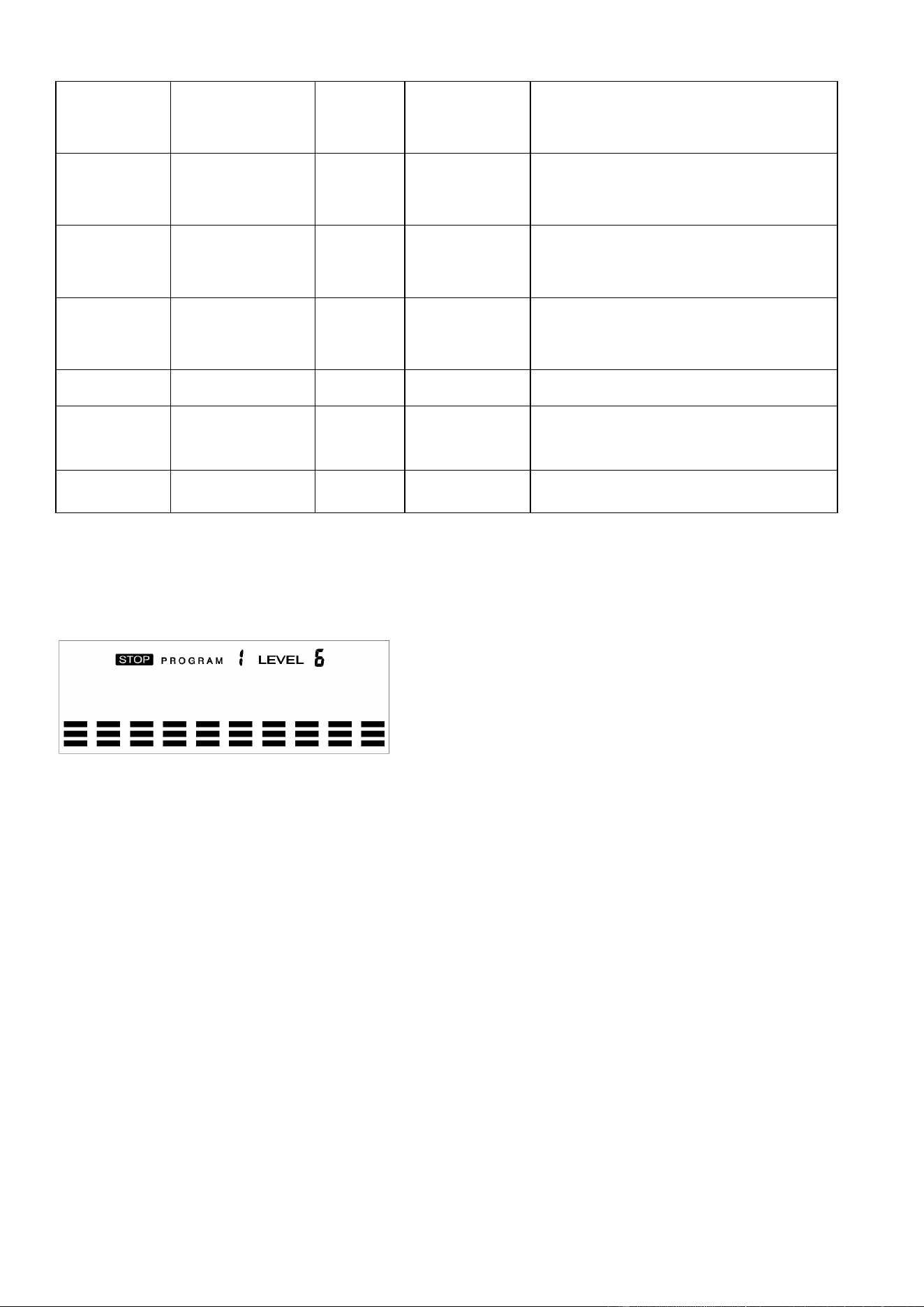
PROGRAM OPERATION
:
Manual (P1)
Program profile
SETTING PARAMETERS FOR MANUAL PROGRAM
1. Select Manual Program (P1) using the UP or DOWN button, then press ENTER.
2. TIME will flash so the value can be adjusted using the UP or DOWN button.
3. Press the ENTER button to save the value and move to the next parameter to be adjusted.
Note: If you set up the target time for workout, then the next parameter of Distance
cannot be adjusted.
4. Continue through all desired parameters and press the START/STOP button to begin the
workout.
Note: Once the workout parameter counts down to zero, it will beep and stop the workout
automatically. Press the START button to continue the workout to reach the unfinished
workout parameter.
16
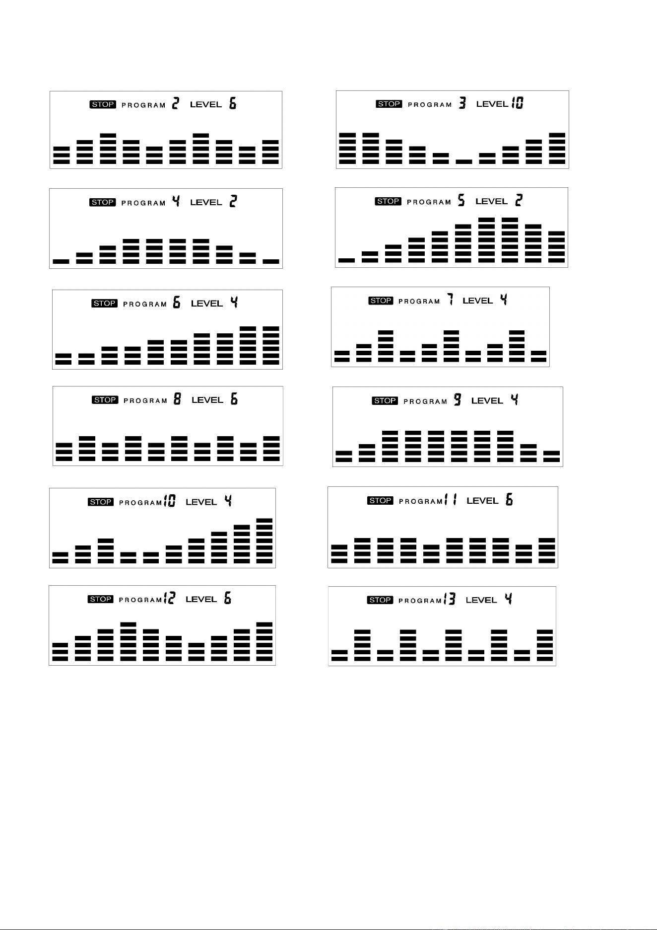
Pre-set programs (P2~P13)
Program profile
There are 12 pre-set programs ready for use. All program profiles have 16 levels of
resistance.
SETTING PARAMETERS FOR PRE- SET PROGRAMS
1. Select one of the Pre-set Programs using the UP or DOWN button, then press ENTER. TIME
will flash so the value can be adjusted using the UP or DOWN key.
2. Press the ENTER button to save value and move to the next parameter to be adjusted.
Continue through all desired parameters, pressing the START/STOP button to begin the
workout.
17
Workout in any pre-set program
You can adjust the level of resistance by pressing the UP or DOWN button during the workout.
Note: If you set up the target time for workout, then the next parameter of Distance cannot
be adjusted. Once the workout parameter counts down to zero, it will beep and stop the
workout automatically. Press the START button to continue the unfinished parameter.
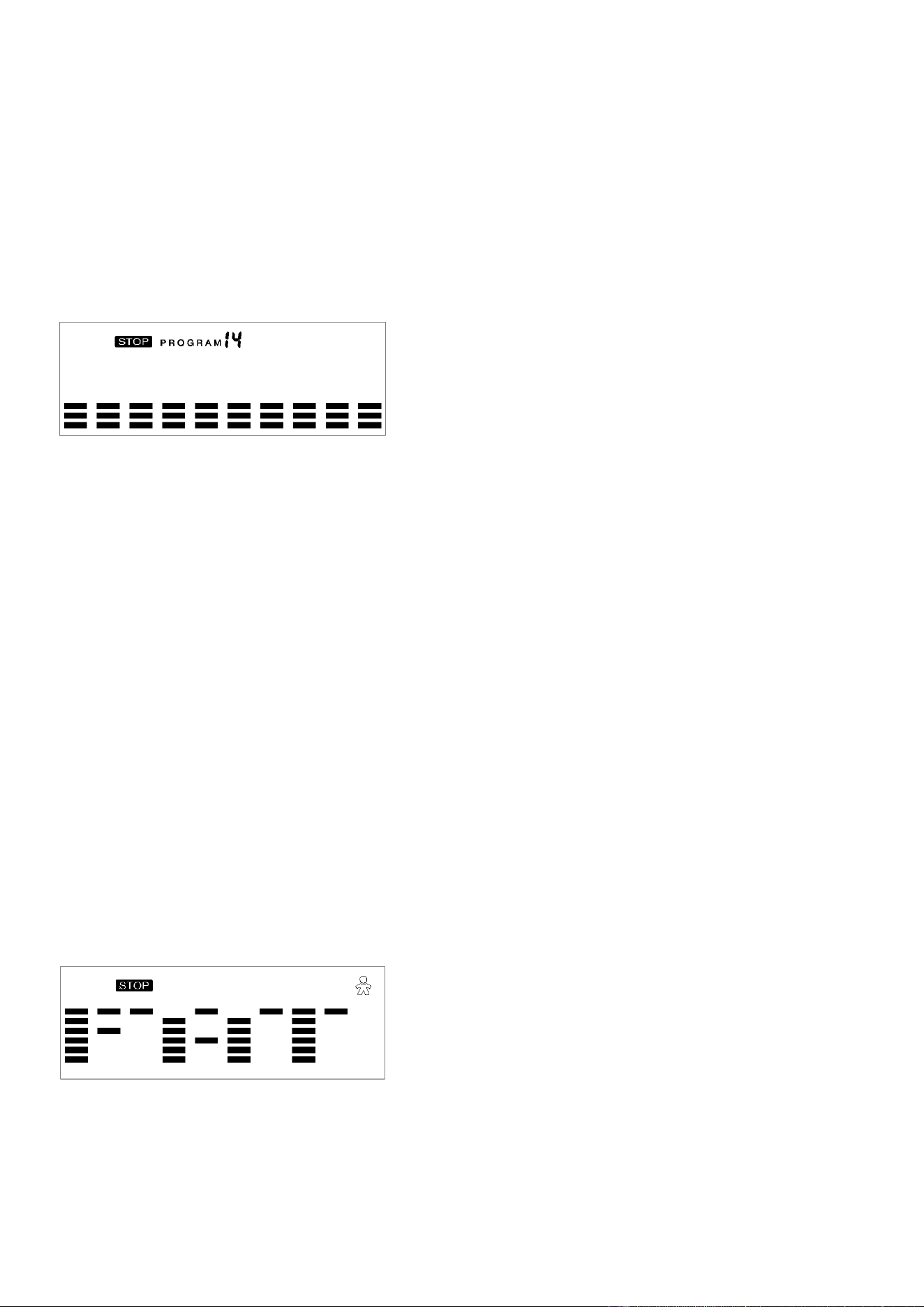
Watt Control Program (P14)
Program profile
SETTING PARAMETERS FOR THE WATT CONTROL PROGRAM
1. Select Watt Control Program (P14) using the UP or DOWN button, then press ENTER.
2. TIME will flash so the value can be adjusted using the UP or DOWN button.
3. Press ENTER button to save the value and move to the next parameter to be adjusted.
Note: If you set up the target time for workout, then the next parameter of Distance
cannot be adjusted.
4. Continue through all desired parameters, pressing the START/STOP button to start the
workout.
Note: Once the workout parameters count down to zero, it will beep and stop the workout
automatically.
5. Press the START button to continue the workout to reach the unfinished workout parameter.
The computer will adjust the resistance load automatically depending on the speed to
maintain the constant watt value. You can use the UP or DOWN button to adjust the watt
value during the workout.
BODY FAT Program (P15)
Program profile
SETTING DATA FOR BODY FAT
Select BODY FAT Program (P15) using the UP or DOWN button, then press ENTER. “MALE” will
flash so Gender can be adjusted using the UP or DOWN button. Press the ENTER button to save
gender and move to the next data.
18
“5’8 (inches)” of Height will flash so Height can be adjusted using the UP or DOWN button. Press
ENTER to save the value and move to the next data.
“165 (lbs)” of Weight will flash so Weight can be adjusted using the UP or DOWN button. Press
ENTER to save the value and move to the next data.
“30” of Age will flash so Age can be adjusted using the UP or DOWN button. Press ENTER to save
the value.
Press the START/STOP button to start the measurement. Please also remember to grasp the hand
pulse grips. After 15 seconds the display will show Body Fat %, BMR, BMI, & BODY TYPE.
Body Types:
There are 9 body types divided according to the FAT % calculated.
Body Type
FAT %
Body Type
FAT %
Body Type
FAT %
Type 1
5% - 9%
Type 4
20% - 24%
Type 7
35% - 39%
Type 2
10% - 14%
Type 5
25% - 29%
Type 8
40% - 44%
Type 3
15% - 19%
Type 6
30% - 34%
Type 9
45% - 50%
BMR: Basal Metabolism Ratio
BMI: Body Mass Index
Press START/STOP button to return the main display.
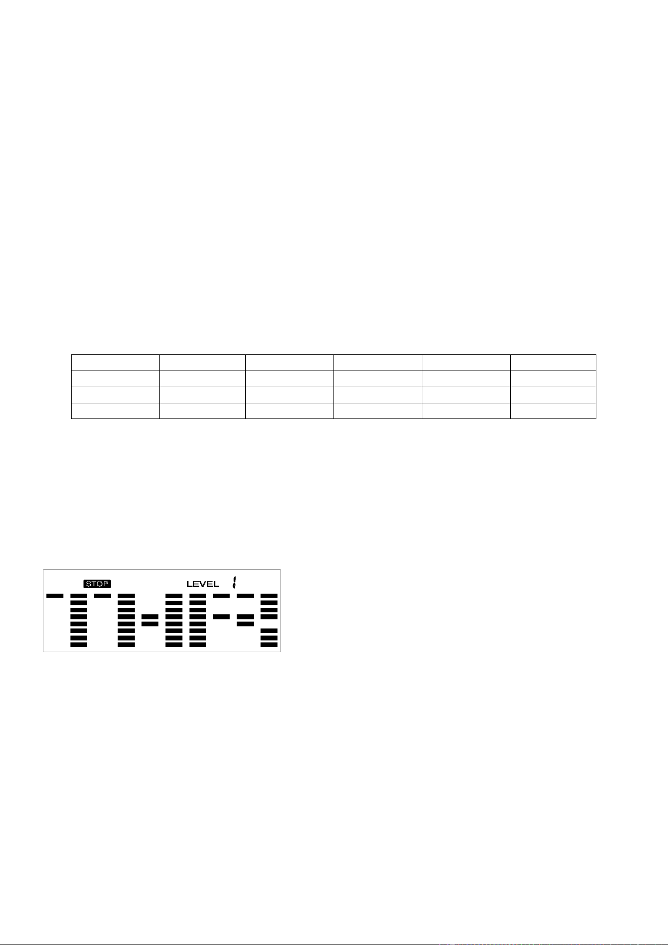
TARGET HEART RATE Program (P16)
Program profile
SETTING PARAMETERS FOR TARGET HEART RATE PROGRAM
1. Select TARGET HR (P16) using the UP or DOWN button, then press ENTER.
2. TIME will flash. The value can be adjusted using the UP or DOWN button.
3. Press the ENTER button to save the value and move to the next parameter to be adjusted.
Note: If you set up the target time to work out, then the next parameter of Distance
cannot be adjusted.
4. Continue through all desired parameters, pressing START/STOP button to start workout.
Note: If Pulse is above the set TARGET HR, the Pulse value will flash to remind the user.
19
HEART RATE CONTROL Program (P17-P20)
Program profile
There are 4 selections for target pulse (HR):
HRC - 55% TARGET HR= 55% of (220-AGE)
HRC - 65% TARGET HR= 65% of (220-AGE)
HRC - 75% TARGET HR= 75% of (220-AGE)
HRC - 85% TARGET HR= 85% of (220-AGE)
SETTING PARAMETERS FOR HEART RATE CONTROL
1. Select one of the Heart Rate Control Programs using the UP or DOWN button, then press
ENTER.
2. TIME will flash. The value can be adjusted using the UP or DOWN button.
3. Press the ENTER button to save the value and move to the next parameter to be adjusted.
Note: If t you set up the target time to work out, then the next parameter of Distance
cannot be adjusted.
4. Continue through all desired parameters, pressing the START/STOP button to start the
workout.
Note: If Pulse is above or below (± 5) the TARGET HR, the computer will adjust the
resistance load automatically. It will check every 20 seconds approx. 1 resistance load
will increase or decrease (Note: each resistance load represents 2 levels of loading).
If one of the workout parameters counts down to be zero, it will beep and stop the
workout automatically. Press the START/STOP button to continue the workout to reach
unfinished workout parameter.

20
User Program
Program profile (P21-P24)
The 4 user programs allow the user to set their own program that can be used immediately.
SETTING PARAMETERS FOR USER PROGRAM
1. Select the User Program using the UP or DOWN button then press ENTER.
2. TIME will flash so the value can be adjusted using the UP or DOWN button.
3. Press the ENTER button to save the values and move to the next parameter to be adjusted.
Note: If the user sets up the target time to workout, then the next parameter for Distance
cannot be adjusted.
4. Continue through all desired parameters.
5. After finishing the setup of the desired parameters, level 1 will flash. Use the UP or DOWN
button to adjust, then press the ENTER button until finished. (There are 10 times total). Press
the START/STOP button to begin the workout.
Note: Once the workout parameter counts down to zero, it will beep and stop the workout
automatically. Press the START/STOP button to continue the workout to reach the
unfinished workout parameter.

21
TROUBLESHOOTING
PROBLEM
POSSIBLE CAUSE
CHECK
SOLUTION
E1
The motor doesn’t
work.
Check if the motor wires are
plugged in or check if the
motor is stuck.
Plug in the cable again
or change the motor.
There is something
wrong with the cables.
Check if the cables are
damaged. This can cause a
short circuit.
Change the cables or
plug in again.
The computer cannot
supply normal voltage
to the motor.
Test whether the voltage of
the
motor is normal when
pressing “up” and “down”.
Change the computer.
E2
The IC (Integrated
Circuits) inside the
computer is damaged.
Change the computer.
E4
Hands aren’t put on the
two handle pulses
immediately after
pressing START.
Put
the hands on the
two handle pulses
immediately after
pressing START.
B
ody Fat Function
cannot receive the
signal for pulse.
Check if the handle pulse
wires are well connected.
Plug in the handle
pulse wires again or
change the handle
pulse wires.
Check if the pulse is working
when not in Body Fat
program.
Change the computer.
NOTE: If you are unable to resolve an issue using the troubleshooting guide above, please
contact Customer Service at [email protected]om
Version 1.5