We value your experience using Sunny Health and Fitness products. For assistance with parts or troubleshooting, please contact us at website or 1-877-90SUNNY (877- 907-8669).
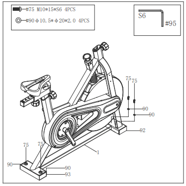
STEP 1:
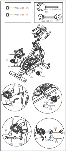
Unscrew 4 Hex Socket Head Bolts (No. 75) from Main Frame (No. 1) with Allen Wrench (No. 95). Remove 4 Flat Washers (No. 90), the Rear Shipping Tube (No. 93), and Front Shipping Tube (No. 92) from Main Frame (No. 1).
You may save these parts [Hex Socket Head Bolts (No. 75), Flat Washers (No. 90), Rear Shipping Tube (No. 93) and Front Shipping Tube (No. 92)] in case you would like to repackage and transport this equipment in the future.
STEP 2:
Attach the Front & Rear Stabilizers (No. 5 & No. 6) to the Main Frame (No. 1) using 4 Hex Socket Bolts (No. 79) and 4 Flat Washers (No. 74). Tighten and secure with Allen Wrench (No. 95).
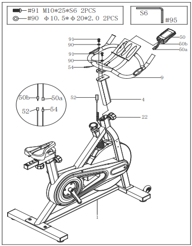
STEP 3:
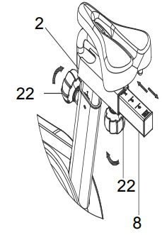
Loosen and pull out Adjustment Knob (No. 22), insert Handlebar Post (No. 4) into Main Frame (No. 1) and adjust to the desired height. Secure it in place by reinserting and tightening the Adjustment Knob (No. 22).
Attach Handlebar (No. 9) onto Handlebar Post (No. 4) with 2 Hex Socket Head Bolts (No. 91) and 2 Flat Washers (No. 90). Secure and tighten with Allen Wrench (No. 95).
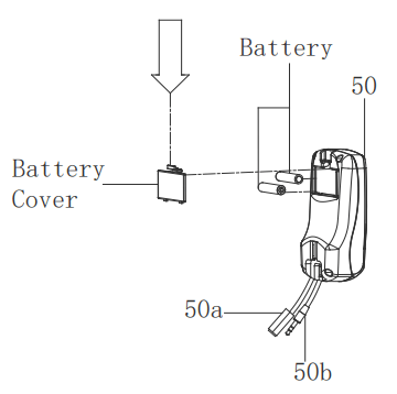
Insert Computer (No. 50) into the computer bracket located on Handlebar (No. 9). Be sure not to pinch the Computer Wire A (No. 50a) and Computer Wire B (No. 50b). Connect Computer Wire A (No. 50a) with Handle Pulse Wire (No. 54) on Handlebar (No. 9) and connect Computer Wire B (No. 50b) with Sensor Wire (No. 52).
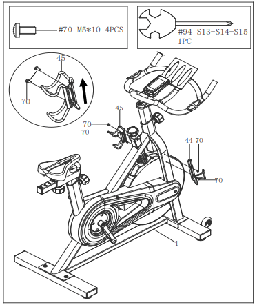
STEP 4:
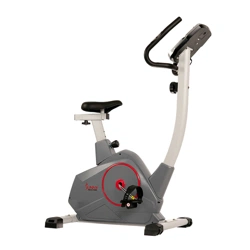
Attach Water Bottle Holder (No. 44) and Dumbbell Holder (No. 45) onto the Main Frame (No. 1) with 4 Pan Head Screws (No. 70). Tighten and secure with Spanner (No. 94).
Note: please assembly the Dumbbell Holder (No. 45) as the arrow showed on the left picture.
STEP 5:
WARNING! Read instructions carefully as improper assembly may cause permanent damage to your bike.
Note: The Pedals (No. 15L & NO. 15R) are marked “L” and “R” for Left and Righ.
Remove the Left & Right Nylon Nuts (No. 84L/R) located on the Left & Right Pedals (No. 15L/R) with Wrench (No. 96).
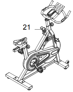
Turn the Tension Control Knob (No. 21) clockwise as tightly as you can with your hand.
Align the Left Pedal (No. 15L) with the Left Crank (No. 14L) at 90°. Turn the pedal bolt on the Left Pedal (No. 15L) COUNTER-CLOCKWISE as tightly as you can with your hand. Then, use Spanner (No. 94) to tighten and secure.
Turn the Left Nylon Nut (No. 84L) CLOCKWISE as tightly as you can with your hand. Use Spanner (No. 94) to hold the pedal bolt on the Left Pedal (No. 15L) and use Wrench (No. 96) to turn the Left Nylon Nut (No. 84L) CLOCKWISE at the same time, until it is tightened on to the Left Crank (No. 14L).
Align the Right Pedal (No. 15R) with the Right Crank (No. 14R) at 90°. Turn the pedal bolt on Right Pedal (No. 15R) CLOCKWISE as tightly as you can with your hand. Then, use Spanner (No. 94) to tighten and secure.
Turn the Right Nylon Nut (No. 84R) COUNTER-CLOCKWISE as tightly as you can with your hand. Use Spanner (No. 94) to hold the pedal bolt on the Right Pedal (No. 15R) in place. Then use Wrench (No. 96) to turn Right Nylon Nut (No. 84R) COUNTER-CLOCKWISE at the same time, until it is tightened on to the Right Crank (No. 14R).
The assembly is complete!
BATTERY INSTALLATION AND REPLACEMENT
BATTERY INSTALLATION:
Take out 2 AAA batteries from the plastic bag for manual.
Press the buckle of battery cover on the back of the Computer (No. 50), then remove battery cover.
Install 2 AAA batteries into the battery case on the back of the Computer (No. 50). Pay attention to the battery + and – ends before installing.
Press the buckle of battery cover, then put the battery cover back to the back of the Computer (No. 50).
The installation is complete!
BATTERY REPLACEMENT:
Press the buckle of battery cover on the back of the Computer (No. 50), then remove battery cover.
Remove the 2 old AAA batteries in the battery case and install 2 new AAA batteries into the battery case on the back of the Computer (No. 50). Pay attention to the battery + and – ends before installing.
Press the buckle of battery cover, then put the battery cover back to the back of the Computer (No. 50).
The replacement is complete!
NOTE: Always change both batteries at the same time. Do not mix battery types and do not mix old and new batteries. Dispose batteries according to your state and regional guidelines
ADJUSTMENTS AND USAGE GUIDE
ADJUSTING THE HEIGHT AND BALANCE
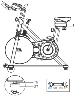
In order to achieve a smooth and comfortable ride, you must ensure that the stability of the bike is secured. If you notice that the bike is unbalanced during use, adjust the Adjustment Foot Pad (No. 37), located beneath the Front & Rear Stabilizers (No. 5 & No. 6) of the bike. To do so, use Wrench (No. 96) to loosen Hex Thin Nut (No. 76) by turning it clockwise (direction A). With the nut loosened, rotate the Adjustment Foot Pad (No. 37) until it sits level with the surface that the bike is on. When you have finished adjusting the Adjustment Foot Pad (No. 37), re-tighten the Hex Thin Nut (No. 76) by turning it counter-clockwise (direction B) to complete the balance adjustment of the bike. If needed, repeat this process to adjust the remaining adjustment foot pad.
ADJUSTING THE RESISTANCE
Adjust the resistance of the bike using the Tension Control Knob (No. 21). Increase the level of resistance by turning the Tension Control Knob (No. 21) to the RIGHT (clockwise), decrease the level of resistance by turning the Tension Control Knob (No. 21) to the LEFT (counter-clockwise).
EMERGENCY BRAKE
During use, users can stop the bike completely by pushing down on the Tension Control Knob (No. 21). Pushing down on the Tension Control Knob (No. 21) will enforce the brake and bring the bike to an immediate stop.
ADJUSTING THE SEAT
The seat of this bike is fully adjustable as it moves Up, Down, Fore (forward), Aft (backward).
To adjust the height of Seat Post (No. 2), loosen and pull the Adjustment Knob (No. 22) outward, then raise or lower the seat to the desired height. Once adjusted, re-insert and tighten the Adjustment Knob (No. 22) to secure the Seat Post (No. 2) in place.
To adjust the seat back and forth, loosen and pull the Adjustment Knob (No. 22) outward, then slide the Seat Slider (No. 8) to desired position. Once positioned, re-insert and tighten the Adjustment Knob (No. 22) to secure the Seat Slider (No. 8) in place.
ADJUSTING THE HANDLEBAR
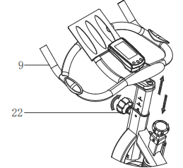
It is important that the handlebar and seat are both set to the correct height to your body. To adjust the handlebar height, loosen and pull the Adjustment Knob (No. 22) outward, then slide the Handlebar (No. 9) up or down to the desired height. Once adjusted, re-insert and tighten the Adjustment Knob (No. 22) to secure the handlebar in place.
PEDAL STRAP ADJUSTMENT
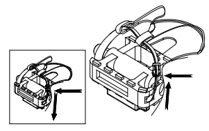
Your feet should be secured in the toe clips during exercise. Place your feet as far forward into the toe clips as you can. With your feet in place, turn the crank to bring one foot to within arm’s reach, grasp the pedal strap and pull it upward to tighten the toe clip cage. Then insert the strap back into the hoop of the toe clip. Repeat this process to secure your other foo
TRANSPORTING THE BIKE
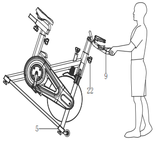
To move the bike, first ensure that the Handlebar (No. 9) is properly secured. If the handlebar is loose, tighten the Adjustment Knob (No. 22) to secure it. Next, stand at the front of the bike so that you’re directly in front of the handlebar. Firmly grasp and hold each side of the Handlebar (No. 9), place one foot on the Front Stabilizer (No. 5), and tilt the bike towards you until the transportation wheels on the Front Stabilizer (No. 5) touch the ground. With the wheels on the ground, you can transport the bike to the desired location with ease.
NOTE: Always use caution when moving the bike. Unexpected impact, such as dropping the bike, may cause injury and affect the bike’s operation
DISMOUNTING
For your safety, it is recommended that you never attempt to dismount or remove your feet from the pedals until both the flywheel and pedals/cranks have come to a complete stop. Failure to follow this recommendation may lead to loss of control and/or serious injury.
Here are a few examples of how to safely dismount the bike:
Reduce the pedal speed until the pedals/cranks come to a complete stop.
Increase the resistance until the pedals/cranks come to a complete stop.
Push and hold the tension control knob down until the pedals/cranks come to a complete stop.
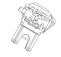
SPD TECHNICAL SERVICE INSTRUCTIONS
Caution!
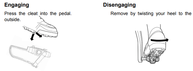
Before use, read these instructions carefully.
Practice engaging and disengaging from the pedals several times in a stationary position before riding.
Before using, lubricate the concave area of the clip.
Keep the cleat and pedal clean to ensure proper usage.
Before using, adjust the retention force of the pedal to suit your needs.
Note:
After tightening the cleat, practice engaging and releasing one shoe at a time.
Check your pedals each time before you ride the bike.
When the pedal starts to wear on the axle, it will not function properly. We recommend you replace the entire pedal.
USE
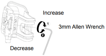
ADJUSTING THE SPRING TENSION OF THE BINDING
The tension of the spring is adjusted for each pedal (top & bottom) with the adjustment bolt in the rear using a 3mm Allen Wrench.
Using a 3mm Allen Wrench, turn the bolt in a clockwise direction to increase retention force. Turn the bolt in a counter-clockwise direction to decrease retention force.
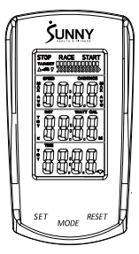
EXERCISE COMPUTER
FUNCTION BUTTONS
MODE:
Press to select the function displayed or during setting mode.
Press and hold for 2 seconds to enter the RACE MODE interface during stop mode.
SET:
To set up the target value of TARGET, TIME, DIST, CAL.
Press the button and hold for 2 seconds to speed up the increment during stop mode.
RESET:
Press the button to reset function value during setting mode.
Press the button and hold for 2 seconds to reset all value to zero.
(When the user replaces the batteries, all values will reset to zero.)
FUNCTIONS:
SPEED: Displays the speed from 0 to 99.9 KPH or MPH.
AVG SPEED: Displays the average speed only in STOP mode.
MAX SPEED: Displays the maximum speed only in STOP mode.
CADENCE (RPM): Displays the frequency per minute from 0 to 999.
AVG CADENCE (AVG RPM): Displays the average cadence (RPM) in STOP mode.
MAX CADENCE (MAX RPM): Displays the maximum cadence (RPM) in STOP mode.
DISTANCE (DIST): Accumulates total distance from 0.0 to 999.9 KM or Miles. User can preset TARGET DISTANCE by pressing MODE & SET.
TARGET DISTANCE (TGT DIST): Users can preset the Distance in the TARGET mode.
CALORIES (CAL): Accumulate total Calories from 0.0 to 9999. User can preset target calories.
RACE: Exercise in the TARGET MODE.
TIME: Accumulates total time from 00:00 to 99:59. User can preset target Time.
TARGET TIME: Users can preset the Time in the TARGET MODE.
PULSE: Display the current pulse rate.
MILES OR KILOMETERS SETTING:
The default setting is miles. Press and hold SET and MODE together for 2 seconds to change to kilometers.
SET TARGET VALUES:
Press SET to select a target value. CADENCE will start to flash.
Press and hold SET and the value will increase continuously.
Press MODE to enter.
TIME will flash.
Press SET to select a value.
Press MODE to enter.
Repeat to select values for DIST and CAL.
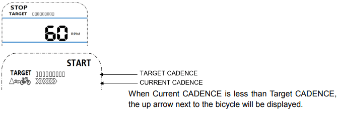
TARGET
TARGET: the preset CADENCE.
In STOP mode, press SET key to enter the TARGET setting in stop mode. Press SET to increase the CADENCE five at a time. The setting change is 15 →20→ ……110→115→120→15→20→……→115→120→ 15 →20→ ……
The setting range of 15 -120 (Preset value is 60 CADENCES which equals six bars).
Each bar equals 10 CADENCE. Total is 12 bars.
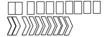
Each arrow equals 10 CADENCES (1-10 CADENCES displays one arrow, 11-20 displays two). The maximum arrows displayed is 12.
This down arrow next to the bicycle icon will be displayed when the current CADENCE is more than the TARGET CADENCE. The bicycle icon will be displayed during exercise mode.
RACE MODE:
Press and hold MODE for 2 seconds to enter RACE mode. In RACE MODE, only TIME and DIST can be set.
Default values for 10 minutes / 4 (KM or Miles). Total is 10 bars.
PULSE:
To measure the pulse, press MODE until computer is on the PULSE function. Hold the handle pulse sensor for at least 5 seconds to measure your pulse. This value is for reference only. It cannot be used as the basis for medical treatment.
BATTERY:
This computer uses two AAA batteries. If the display appears incorrectly or becomes difficult to read, please install new batteries. Always change both batteries at the same time. Do not mix battery types and do not mix old and new batteries. Dispose batteries according to your state and regional guidelines.
MAINTENANCE INSTRUCTIONS
This is general information for daily, weekly and monthly maintenance to be performed on your bike.
DAILY MAINTENANCE
After each exercise session, wipe down all the equipment: seat, frame, and handlebars. Pay special attention to the seat post, handlebar post and belt/chain guard. Sweat is very corrosive and may cause problems that require parts replacement later.
Get on the bike and engage the drive train.
Pay attention to any vibrations felt through the pedals. If you feel any vibrations, you may need to tighten the pedals, bottom bracket, or adjust the drive belt/chain tension.
Use a wrench to tighten the pedals until they are secure.
MONTHLY MAINTENANCE
Check if all hardware is secure, such as: water bottle holder, flywheel nuts, belt/chain guard bolts, brake caliper lock nuts, and brake caliper tension rod nuts.
Inspect the brake tension rod for signs of wear such as missing threads. Clean and lubricate the brake tension rod.
Clean and lubricate the seat post, handlebar post and seat slider. Remove any buildup of foreign material.
WEEKLY MAINTENANCE
Inspect moving parts and tighten the hardware.
Inspect pull pin frame fittings to make sure the fittings are snug. Loose frame fittings may strip out threads over time and cause extensive damage.
Clean and lubricate pop pin assemblies. Pull on the pin and spray a small amount of lubricant onto the shaft.
Tighten the seat hardware to make sure the seat is level and centered.
Brush and treat the resistance pads. Remove any foreign material that may have collected on the pads. Spray the pads with silicone lubricant. This helps to reduce noise from friction between the pads and the flywheel.
Visually inspect the bottom bracket, toe clips and toe straps. If any of them are loose or disconnected, attach and tighten.
LEATHER BRAKE PAD CARE (If applicable)
Perform this maintenance when the brake pad is first installed and for the life of the brake pad. Following these simple guidelines can increase the life of your brake pads.
Some brake pad assemblies are pre-lubricated. Squeeze the brake pad. If lubricant is released, then the pad has been pre-lubricated.
If the brake pad is dry, then coat the brake pad with 3-n-1 oil. Brush the leather with a clean, wire bristle brush, and then apply the oil. The oil should be allowed to soak into the pad. Repeat 4-5 times until the pad is saturated, but not dripping with oil. When the pad is saturated, it will no longer absorb oil.
Inspect the brake pad weekly and lubricate if needed. The pad should not have a glazed appearance. If the pad appears glazed, then brush it with wire brush and apply lubricant as needed. If any of the sponge padding is showing through the leather pad, the brake pad should be replaced.