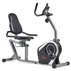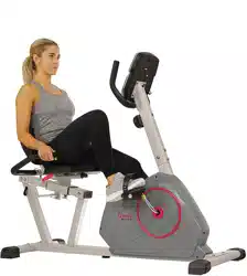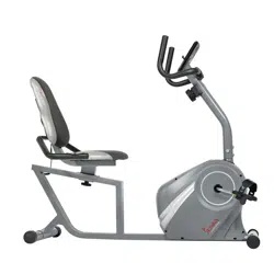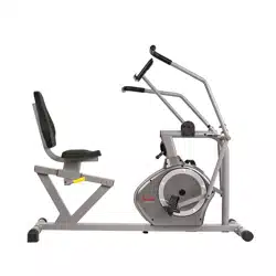
MAGNETIC RECUMBENT BIKE
SF-RB4806
USER MANUAL
IMPORTANT! Please retain owner’s manual for maintenance and adjustment instructions. Your satisfaction
is very important to us, PLEASE DO NOT RETURN UNTIL YOU HAVE CONTACTED US:
support@sunnyhealthfitness.com or 1- 877 - 90SUNNY (877-907-8669).

1
IMPORTANT SAFETY INFORMATION
We thank you for choosing our product. To ensure your safety and health, please use this
equipment correctly. It is important to read this entire manual before assembling and using the
equipment. Safe and effective use can only be achieved if the equipment is assembled, maintained,
and used properly. It is your responsibility to ensure that all users of the equipment are informed of
all warnings and precautions.
1. Before starting any exercise program, you should consult your physician to determine if you
have any medical or physical conditions that could put your health and safety at risk or prevent
you from using the equipment properly. Your physician’s advice is essential if you are taking
medication that affects your heart rate, blood pressure, or cholesterol level.
2. Be aware of your body’s signals. Incorrect or excessive exercise can damage your health. Stop
exercising if you experience any of the following symptoms: pain, tightness in your chest,
irregular heartbeat, shortness of breath, lightheadedness, dizziness, or feelings of nausea. If
you do experience any of these conditions, you should consult your physician before continuing
with your exercise program.
3. Keep children and pets away from the equipment. The equipment is designed for adult use only.
4. Use the equipment on a solid, flat level surface with a protective cover for your floor or carpet.
To ensure safety, the equipment should have at least 2 feet (60 CM) of free space all around it.
5. Ensure that all nuts and bolts are securely tightened before using the equipment. The safety of
the equipment can only be maintained if it is regularly examined for damage and/or wear and
tear.
6. Always use the equipment as indicated. If you find any defective components while assembling
or checking the equipment, or if you hear any unusual noises coming from the equipment during
exercise, discontinue use of the equipment immediately and do not use until the problem has
been rectified.
7. Wear suitable clothing while using the equipment. Avoid wearing loose clothing that may
become entangled in the equipment.
8. Do not place fingers or objects into the moving parts of the equipment.
9. The maximum weight capacity of this unit is 220 pounds (100 KG).
10. The equipment is not suitable for therapeutic use.
11. To avoid bodily injury and/or damage to the product or property, proper lifting and moving are
required.
12. Your product is intended for use in cool and dry conditions. You should avoid storage in extreme
cold, hot or damp areas as this may lead to corrosion and other related problems.
13. This equipment is designed for indoor and home use only; it is not intended for commercial use.

2
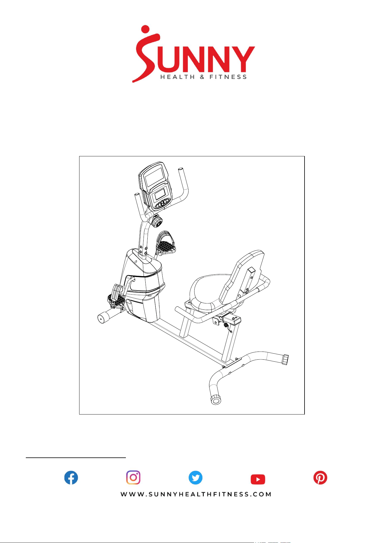
EXPLODED DIAGRAM 1
S13
#91 S5 1PC
#93 S13-14-15 1PC
#92 S6 1PC
S14
S15
1
2
1a
1b
3
4
5
6
7
8
9
9
9
9
10
10
10
10
10
10
10
11
11
11
11
11
11
8
12
15
13
14
16
17
18
18
19
21
21
21
21
20
20
22L
22R
23
24
24
25
26
27
27
28
28
29
29
30
30
31
32
32
20
33
33
33
34
34
34
34
34
34
34
34
34
33
33
33
35
35
36
36
37
21
38
39
39
40
40
41
42
43
44
44
45
46
47
48
49
50
51
52
53
54
55
10
34
94
94
96
97
97
3
EXPLODED DIAGRAM 2
56
58
60
61
62
63
62
63
59
7 4
33
73
7 2
71
70
68
68
67
66
76
7 7
78
79
80
81
8 8L
88 R
89
90
90
89
9 0
9 0
89
90
89
90
82
83
84
85
86
87
69
7 5
95
86
57
65
64
61
HARDWARE PACKAGE
#20 M8*60*20*H5 1PC
#21 M8*H16*S13 1PC
#34 d8*Φ16*1.5 8PCS
#10 M8*16*S6 5PCS
#33 d8 2PCS
S13
S14
S15
S6
#92
#93 S13-14-15
#91
S5
#43 M8*50 2PCS

4
PARTS LIST
No. Description Spec. Qty.
No. Description Spec. Qty.
1 Computer 1
28 Screw ST4.0*19 2
1a Computer Wire 1
29 Handle Pulse Plate 2
1b Computer Wire 1
30 Foam Grip Φ23*3*520 2
2 Bolt M5*10 4
31 Slider 1
3 Bolt M5*40*Φ8 1
32 Square End Cap J60*30 2
4 Arc Washer d5*Ф20*R30*1.5 1
33 Spring Washer d8 11
5
Tension Control
Knob
1
34 Washer d8*Φ16*1.5 20
6 Lower Wire 1
35 Bolt M8*45 4
7 Front Handlebar 1
36 Square End Cap F38*38*14 2
8 Foam Grip Φ23*3*340 2
37 Backrest Frame 1
9 Round End Cap Φ25*16 4
38
Backrest Frame
Support
1
10 Bolt M8*16*S6 13
39 Bushing J80*40 2
11 Arc Washer d8*Φ20*2*R30 8
40 Screw ST3*6 4
12 Handlebar Post 1
41 Fixed Plate For Handlebar 1
13
Sensor Wire
Extension
1
42 Bolt M6*16 2
14 Pulse Wire 1
43 Bolt M8*50 2
15
Pulse Wire
Extension
1
44 Bolt M8*20 4
16 Sensor Wire 1
45 Bushing
For Adjusted
Handlebar
1
17 Main Frame 1
46 Adjusted Handlebar 1
18 End Cap 2
47 Washer D12 1
19 Front Stabilizer 1
48 Eccentric Wheel 1
20 Bolt M8*60*20*H5 3
49 Clamp 1
21 Cap Nut M8*H16*S13 5
50 Bolt M8*10 1
22L/R
Pedal 2
51 Clamp Shaft 1
23 Rear Stabilizer 1
52 Bolt M6*20 2
24 End Cap 2
53 Arc Washer d6*Ф16*1.5*R16 2
25 Rear Handlebar 1
54 Backrest Cushion 1
26 Handle Pulse Wire 1
55 Seat Cushion 1
27 Grommet Φ12*11*Φ3 2
56 Screw ST4.2*16 1

5
No. Description Spec. Qty.
No. Description Spec. Qty.
57 Crank 1
78 Idler wheel 1
58 Belt Plate 1
79 Bolt M6*16 1
59 Magnet Φ15*7 1
80 Washer d8*Φ20*2 1
60 Belt
1
81 Nylon Nut M8*H7.5 1
61 Locking Nut
2
82 Magnet 4
62 Open Face Bearing
2
83 Washer d8 1
63 Bearing Housing
2
84 Magnetic Plate 1
64 Locking Washer
1
85 Bolt M5*16 1
65 Hexagon Nut
1
86 Nut M5*H4 2
66 Flywheel Shaft Φ21*35*84-9PJ 1
87 Spring Φ1.2*Φ15*48*N9
1
67 Wave Washer d15 1
88L/R
Belt Cover 2
68 Bearing 6202 2
89 Screw ST4.2*16 4
69 C-clip d15 1
90 Screw ST4.2*19 6
70 Wave Washer d31.5 1
91 Allen Wrench S5 1
71 C-clip d35 1
92 Allen Wrench S6 1
72 Flywheel 2KG 1
93 Spanner S13-14-15 1
73 Washer d8*Φ25*2 1
94 Bolt ST4.2*16 2
74 Bolt M8*16 1
95 Washer d6*Φ16*1.5 1
75
Idler Wheel Connect
Staff
1
96 Spring Washer d6 2
76 Spring
Φ3.2*Φ20.2*70*
N10
1
97 Bolt M8*55*20*H5 2
77 Wave Washer d12 1
Ordering Replacement Parts (U.S. and Canadian Customers only)
Please provide the following information in order for us to accurately identify the part(s) needed:
The model number (found on cover of manual)
The product name (found on cover of manual)
The part number found on the “EXPLODED DIAGRAM” and “PARTS LIST” (found near the front
of the manual
Please contact us at [email protected] or 1- 877 - 90SUNNY (877-907-8669).
6
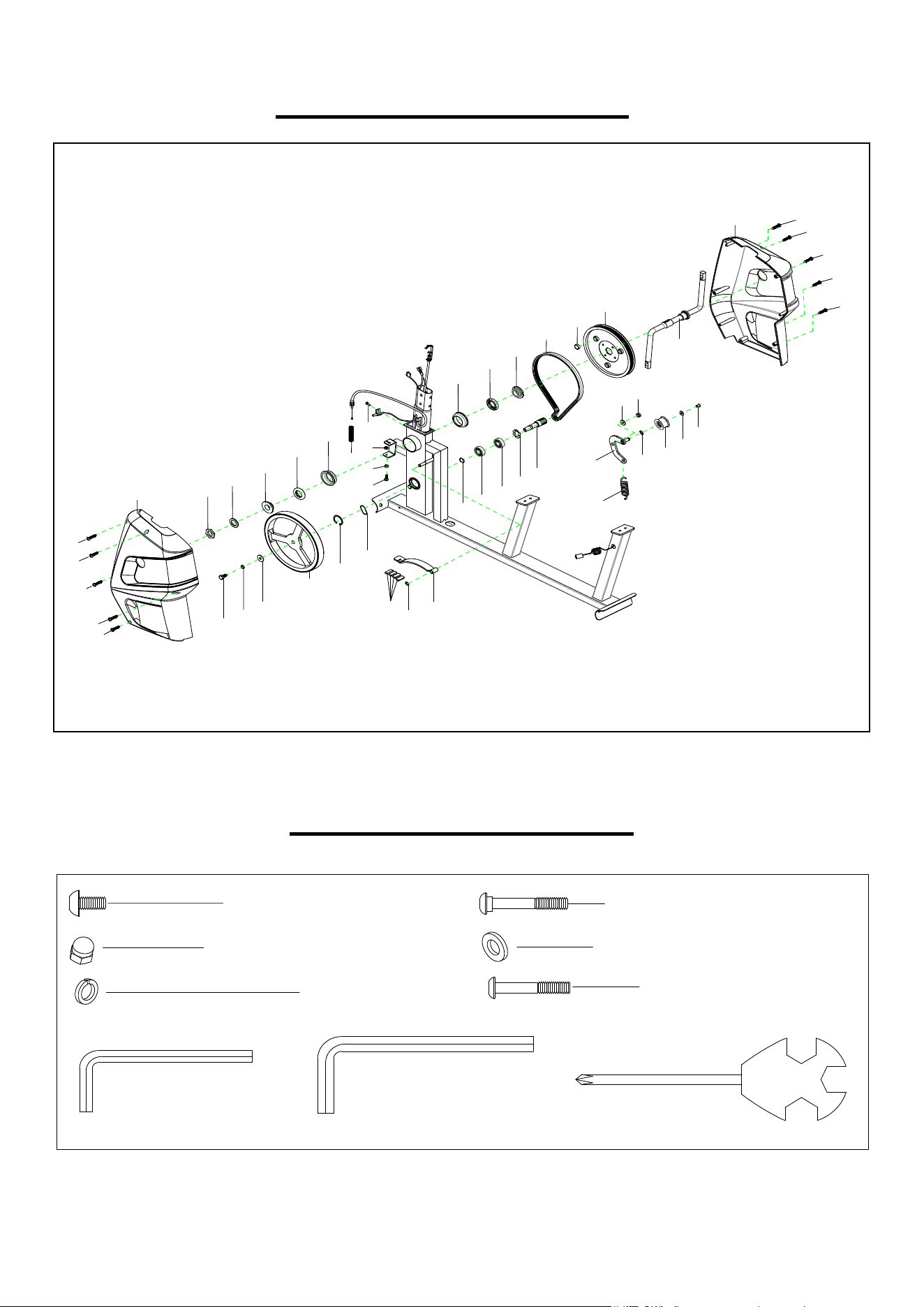
ASSEMBLY INSTRUCTIONS
We value your experience using Sunny Health and Fitness products. For assistance with parts or
(877-907-8669).
# 1 1 d 8 * Φ 2 0 * 2 * R 3 0 4 P C S
# 2 1 M 8 * H 1 6 * S 1 3 4 P C S
S 1 3
S 1 5
# 9 3 S 1 3 - 1 4 - 1 5 1 P C
2 0
2 0
1 1
2 1
1 1
2 1
2 2 L
2 2 R
1 1
2 1
1 1
2 1
1 9
2 3
1 7
5 7
9 7 # M 8 * 5 5 * 2 0 * H 5 2 P C S
2 0 # M 8 * 6 0 * 2 0 * H 5 2 P C S
9 7
9 7
STEP 1:
Remove 2 Bolts (No. 20), 2 Arc Washers
(No. 11), and 2 Cap Nuts (No. 21) from
Front Stabilizer (No. 19) using Spanner
(No. 93). Attach Front Stabilizer (No. 19) to
Main Frame (No. 17) using 2 Bolts (No. 20),
2 Arc Washers (No. 11), and 2 Cap Nuts
(No. 21) that were removed. Tighten and
secure with Spanner (No. 93).
Remove 2 Bolts (No. 97), 2 Arc Washers
(No. 11), and 2 Cap Nuts (No. 21) from Rear
Stabilizer (No. 23) using Spanner (No. 93).
Attach Rear Stabilizer (No. 23) to Main
Frame (No. 17) using 2 Bolts (No. 97), 2 Arc
Washers (No. 11), and 2 Cap Nuts (No. 21)
that were removed. Tighten and secure with
Spanner (No. 93).
Connect the Left & Right Pedals (No. 22L &
No. 22R) onto the Crank (No. 57).
Left Pedal: Align the Left Pedal (No. 22L)
with the left side of Crank (No. 57) at 90
degrees and gently insert the pedal into the
crank arm. Turn the pedal counter-clockwise
as tightly as you can with your hand. Secure
with Spanner (No. 93).
Right Pedal: Align the Right Pedal (No.
22R) with the right side of Crank (No. 57) at
90 degrees and gently insert the pedal into
the crank arm. Turn the pedal clockwise as
tightly as you can with your hand. Secure
with Spanner (No. 93).
7
We value your experience using Sunny Health and Fitness products. For assistance with parts or
troubleshooting, please contact us at support@sunnyhealthfitness.com or 1-877-90SUNNY
(877-907-8669).
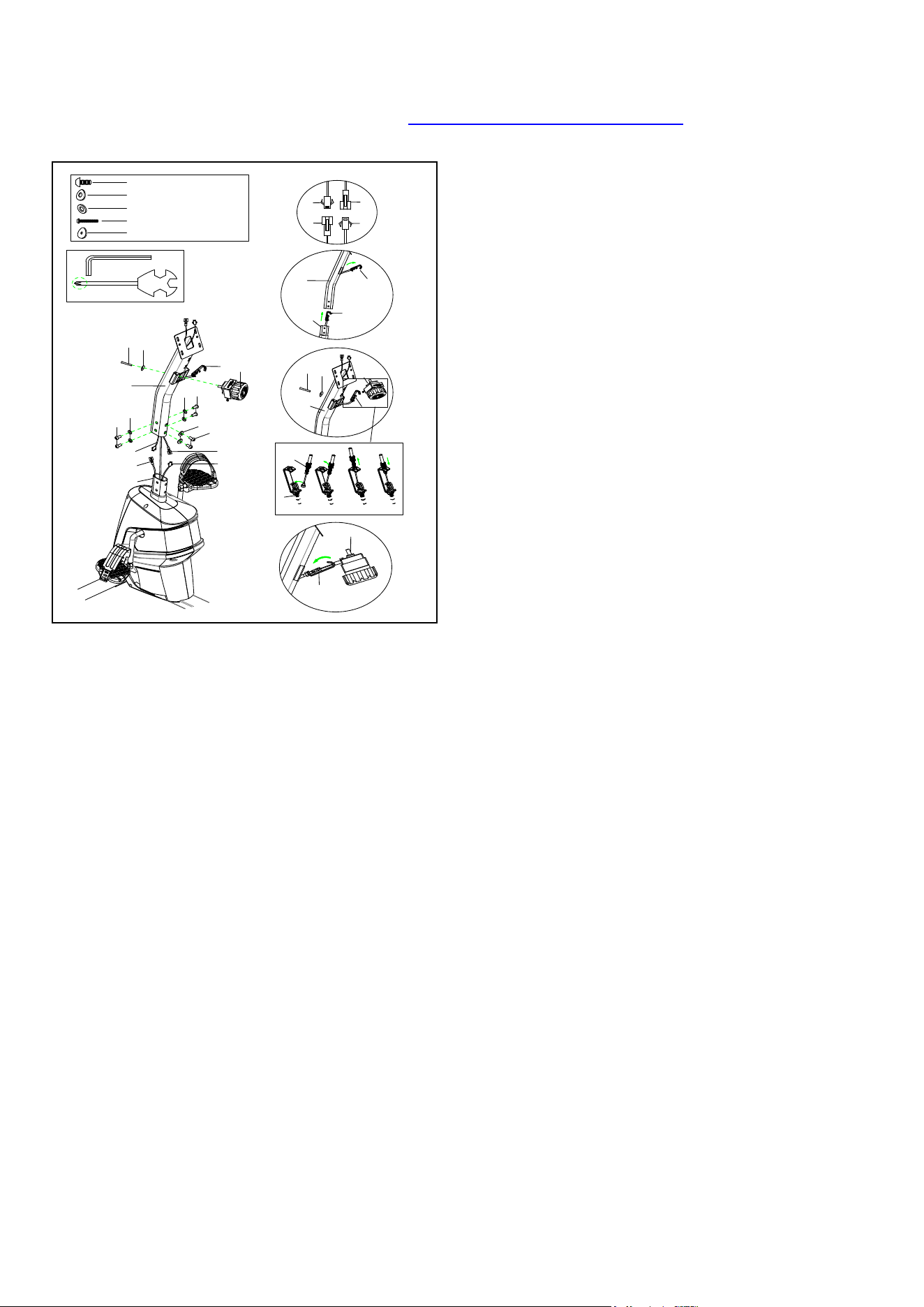
STEP
2
:
Remove 6 Bolts (No. 10), 2 Arc Washers (No.
11), and 4 Washers (No. 34) from Main Frame
(No. 17) using Allen Wrench (No. 92).
Connect Sensor Wire (No. 16) with Sensor
Wire Extension (No. 13) and connect Pulse
Wire (No. 14) with Pulse Wire Extension (No.
15) as shown in picture A. Pull out the Lower
Wire (No. 6) from the hole of Main Frame (No.
17), then insert the Lower Wire (No. 6) into the
bottom hole of the Handlebar Post (No. 12)
and go out through the side hole of the
Handlebar Post (No. 12) as shown in picture
B.
Attach Handlebar Post (No. 12) to Main
Frame (No. 17) using 6 Bolts (No. 10), 2 Arc
Washers (No. 11), and 4 Washers (No. 34)
that were removed. Tighten and secure with
Allen Wrench (No. 92).
Note: Do not clip the wires when assembling
the Handlebar Post (No. 12).
Remove 1 Bolt (No. 3) and 1 Arc Washer (No.
4) from Tension Control Knob (No. 5) using
Spanner (No. 93).
Check the Tension Control Knob (No. 5) is at
level 8 (highest resistance) to ensure the wire is
the longest. Connect Tension Control Knob
(No. 5) with Lower Wire (No. 6) as shown in
picture C, then back Lower Wire (No. 6) into
Handlebar Post (No. 12).
Note: When the Lower Wire (No. 6) is backed
into Handlebar Post (No. 12), the direction
should be correct as shown in picture D.
Attach Tension Control Knob (No. 5) to
Handlebar Post (No. 12) using 1 Bolt (No. 3)
and 1 Arc Washer (No. 4) that were removed.
Tighten and secure with Spanner (No. 93).
A
# 1 1 d 8 * Φ 2 0 * 2 * R 3 0 2 P C S
# 1 0 M 8 * 1 6 * S 6 6 P C S
# 3 4 d 8 * Φ 1 6 * 1 . 5 4 P C S
# 9 2 S 6 1 P C
# 9 3 S 1 3 - 1 4 - 1 5 1 P C
1 0
1 0
1 1
1 2
3 4
1 0
3 4
3
4
5
6
5
6
1 3
1 5
1 4
1 6
1 5
1 4
1 3
1 6
1 7
# 3 M 5 * 4 0 * Φ 8 1 P C
# 4 d 5 * Ф 2 0 * R 3 0 * 1 . 5 1 P C
1 2
5
6
3
4
1 2
6
1 7
6
6
5
D
B
C
8
We value your experience using Sunny Health and Fitness products. For assistance with parts or
troubleshooting, please contact us at support@sunnyhealthfitness.com or 1-877-90SUNNY
(877-907-8669).
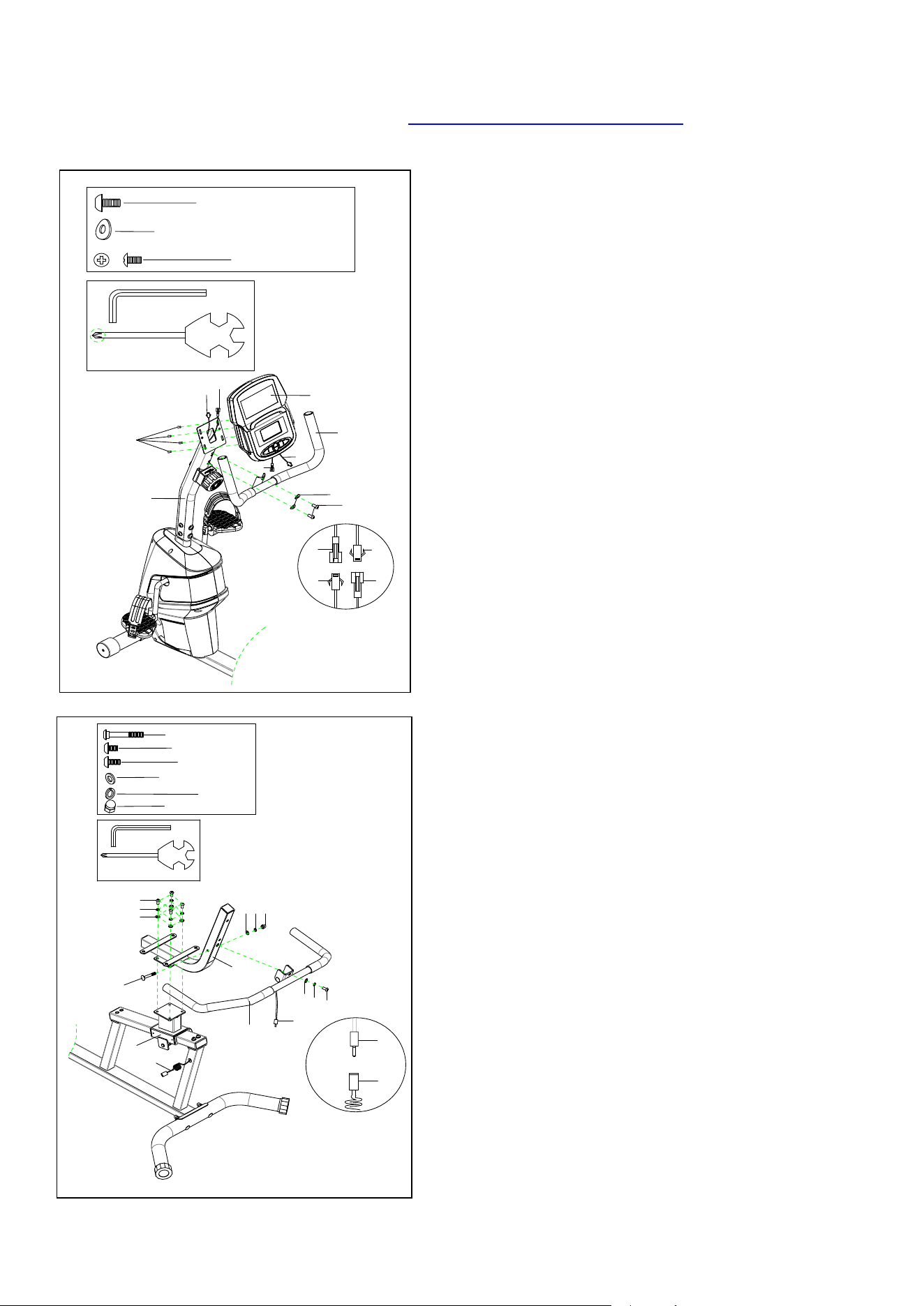
STEP
3
:
Remove 2 Bolts (No. 10) and 2 Arc Washers
(No. 11) from Handlebar Post (No. 12) using
Allen Wrench (No. 92).
Attach Front Handlebar (No. 7) to Handlebar
Post (No. 12) using 2 Bolts (No. 10) and 2 Arc
Washers (No. 11). Tighten and secure with
Allen Wrench (No. 92).
Remove 4 Bolts (No. 2) from Computer (No. 1)
using Spanner (No. 93).
Connect Computer Wire (No. 1b) with Sensor
Wire Extension (No. 13) and connect
Computer Wire (No. 1a) with Pulse Wire
Extension (No. 15). Then, attach Computer
(No. 1) to Handlebar Post (No. 12) using 4
Bolts (No. 2) that were removed. Tighten and
secure with Spanner (No. 93).
STEP
4
:
Remove 4 Bolts (No. 44), 4 Spring Washers
(No. 33), and 4 Washers (No. 34) from
Backrest Frame Support (No. 38) using Allen
Wrench (No. 92).
Attach Backrest Frame (No. 37) to Backrest
Frame Support (No. 38) using 4 Bolts (No.
44), 4 Spring Washers (No. 33), and 4
Washers (No. 34) that were removed. Tighten
and secure with Allen Wrench (No. 92).
Attach Rear Handlebar (No. 25) to Backrest
Frame (No. 37) using 1 Bolt (No. 20), 1 Bolt
(No. 10), 2 Spring Washers (No. 33), 2
Washers (No. 34), and 1 Cap Nut (No. 21).
Tighten and secure with Allen Wrench (No. 92)
and Spanner (No. 93).
Connect Handle Pulse Wire (No. 26) with
Pulse Wire (No. 14).
15
1b
1a
13
#92 S6 1PC
#11 d8*Φ 20*2*R30 2PCS
#10 M8*16*S6 2PCS
#2 M5*10 4PCS
2
1
1a
1b
7
10
11
12
13
15
#93 S13-14-15 1PC
10
20
34
34
33
33
37
44
25
26
14
26
14
38
33
34
21
S13
#92 S6 1PC
#93 S13-14-15 1PC
#44 M8*20 4PCS
#34 d8*Φ16*1.5 6PCS
#20 M8*60*20*H5 1PC
#21 M8*H16*S13 1PC
#33 d8 6PCS
#10 M8*16*S6 1PC

9
We value your experience using Sunny Health and Fitness products. For assistance with parts or
troubleshooting, please contact us at support@sunnyhealthfitness.com or 1-877-90SUNNY
(877-907-8669).
STEP
5
:
Remove 2 Bolts (No. 52), 2 Spring Washers
(No. 96) and 2 Arc Washers (No. 53) from
Adjusted Handlebar (No. 46) using Allen
Wrench (No. 91).
Attach Adjusted Handlebar (No. 46) to Clamp
Shaft (No. 51) using 2 Bolts (No. 52), 2 Spring
Washers (No. 96) and 2 Arc Washers (No. 53)
that were removed. Tighten and secure with
Allen Wrench (No. 91).
Attach Seat Cushion (No. 55) to Backrest
Frame (No. 37) using 4 Bolts (No. 10) and 4
Washers (No. 34). Tighten and secure with
Allen Wrench (No. 92).
Attach Backrest Cushion (No. 54) to Backrest
Frame (No. 37) using 2 Bolts (No. 43) and 2
Washers (No. 34). Tighten and secure with
Allen Wrench (No. 92).
The assembly is complete!
#92 S6 1PC
#91 S5 1PC
#10 M8*16*S6 4PCS
#52 M6*20 2PCS
#43 M8*50 2PCS
#53 d6*Φ16*1.5*R16 2PCS
#34 d8*Φ16*1.5 6PCS
10
34
37
55
55
54
43
34
52
53
46
51
37
96
#96 d6 2PCS
10
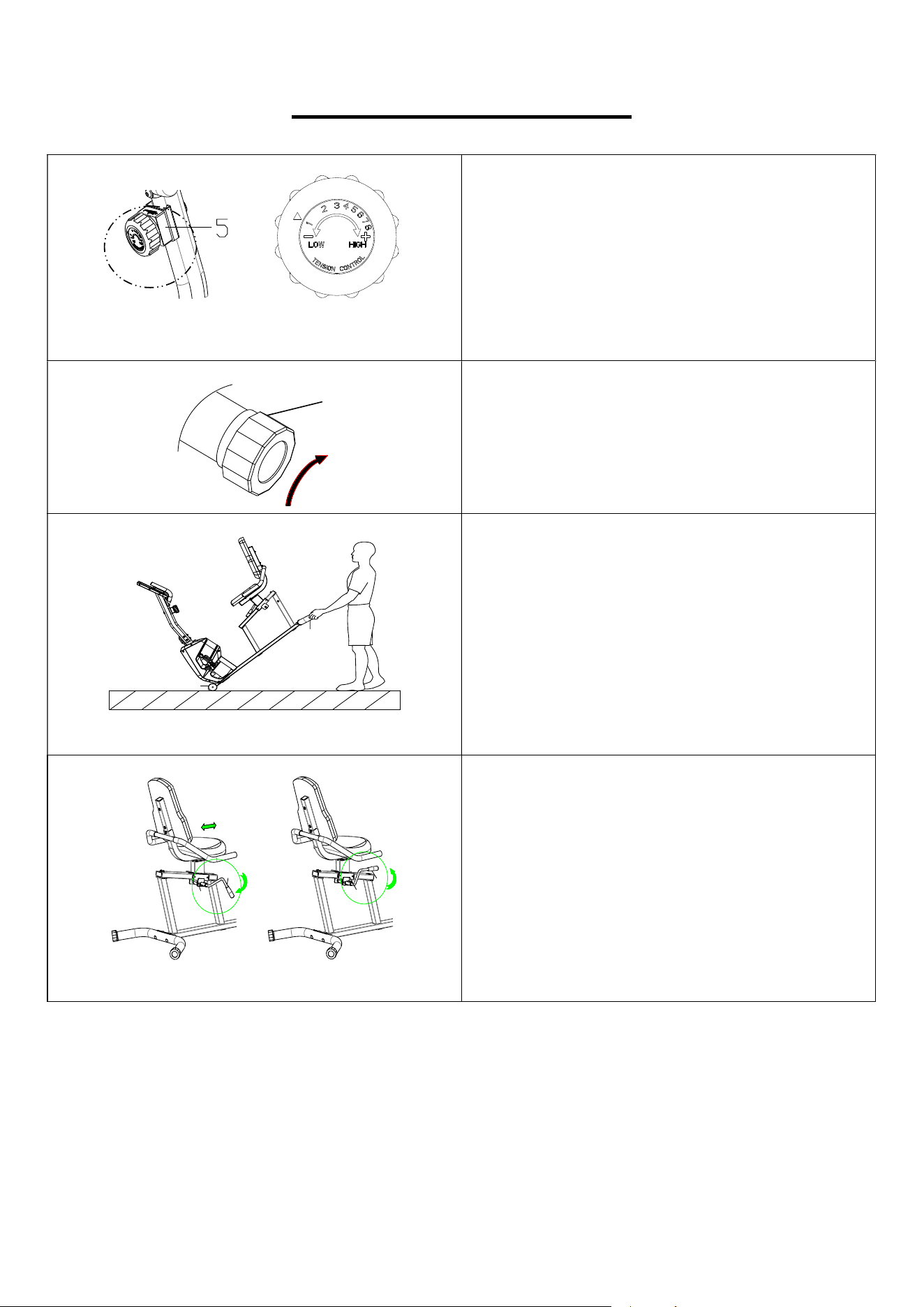
ADJUSTMENTS GUIDE
ADJUSTING THE RESISTANCE
Rotate the Tension Control Knob (No. 5)
clockwise to increase the level of resistance.
Rotate the Tension Control Knob (No. 5)
counter-clockwise to decrease the level of
resistance.
Tension levels are set at Level 1 being the
lowest and Level 8 being the highest.
ADJUSTING THE BALANCE
When this recumbent bike is on an uneven
surface, please adjust both End Caps (No. 24)
according to the left instruction picture.
23
18
MOVING THE RECUMBENT BIKE
To move the recumbent bike, lift the Rear
Stabilizer (No. 23) until transportation wheels
on the End Caps (No. 18) touch the ground.
With the transportation wheels on the End Caps
(No. 18) on the ground, you can transport the
recumbent bike to the desired location with
ease.
46
38
46
38
ADJUSTING THE SEAT
Push the Adjusted Handlebar (No. 46) down to
loosen (see Fig 1). Keep your feet on the floor
as leverage, then move the Backrest Frame
Support (No. 38) to the desired position. Pull
the Adjusted Handlebar (No. 46) up to tighten
(see Fig 2).
24
Fig 1
Fig 2

11
EXERCISE COMPUTER
FUNCTION BUTTONS:
MODE:
1. Press the button to select hour, minute, year, month, and date for setting.
2. Press the button to select TIME, DISTANCE, CALORIES, and PULSE to
preset.
3. Press the button for selection function display on main LCD, or enter after
setting.
4. Press the button to confirm setting values of Gender, Age, Height, and Weight.
5. Press the button and hold for 2 seconds to reset all values to zero.
Note: When the user replaces batteries, all the values will reset to ZERO automatically.
SET:
1. To set up the hour, minute, year, month, and date.
2. To set up the target value of Time, Distance, Calories, and Pulse. You can hold the button to
increase the value fast. (No motion should be detected at the time of setting).
3. To set up the personal data of gender, age, height, and weight for Body Fat measure.
RESET:
Press the button to reset function values.
Note: When the user replaces the batteries, all the values will reset to ZERO automatically.
BODY FAT:
Press this button to enter Body Fat measure function, then press MODE button to enter the setting
mode of your personal data of Gender, Age, Height, and Weight. After setting is complete, press it
again, to measure your Body fat ratio (FAT%) and BMI.
RECOVERY:
To initiate the heart rate recovery function after pulse signal, press any button to return to the main
display.
FUNCTIONS:
SCAN:
Automatically scans through each mode in sequence every 6 seconds. The display loop is RPM -
Speed – Time – Distance – Calorie - Pulse on the main screen.
TIME:
Accumulates total time from 00:00 up to 99:59. The user may preset target time by pressing SET &
MODE button. Each increase is 1 minute.
RPM:
Displays the Rotation per Minute (RPM). The RPM and SPEED will switch to another display every
6 seconds after the exercise starts.
SPEED:
Displays current training speed. Maximum speed is 99.9 mi/h.

12
DISTANCE:
Accumulates total distance from 0.00 up to 99.99 miles. The user may preset target distance data
by pressing the SET & MODE button. Each increase setting is 0.5 miles.
CALORIES:
Accumulates calories burned during training from 0 to 999 calories.
The user may also preset the target calorie before training by pressing the SET & MODE button.
Each setting increase is 10 cal.
Note: This data is a rough guide for comparison of different exercise sessions which cannot
be used in medical treatment.
PULSE: The monitor will display the user's heart rate in beats per minute during training.
You may set the target heart rate by pressing the SET & MODE button.
CALENDAR: The monitor will display date, month, and year when the monitor is in sleep mode.
CLOCK: The monitor will display current clock time when the monitor is in sleep mode.
TEMPERATURE: Displays current room temperature from 50℉ to 140℉ when the monitor is in
sleep mode.
OPERATION ORDER:
1. Power on – Install 2 pieces of 1.5V UM-3 or AA batteries. The monitors display will flash with a
long beep sound.
Note: Whenever batteries are removed, all the functions values will be reset to zero or
default value.
2. Set current data – Press the SET and MODE buttons to set up current clock time, year, month,
and date. After the first setting, until the batteries are replaced next time, the preset data will be
updated automatically.
3. Select and preset target values – Get access to the setting function of Time, Distance, Calories,
and Target Pulse. When you are in each setting mode and the time setting value is flashing, you
can press the SET button to adjust the value. Press the MODE button for confirmation and skip
to the next setting. The setting of Distance & Calories is the same as the Time setting.
4. After entering speed signal, each function of SPEED-RPM-TIME-DISTANCE-CALORIES-
PULSE will skip to display every 6 seconds.
5. You can also press the MODE button to select a single function display on the main screen
except RPM & SPEED. The RPM & SPEED function will switch displays in 6 seconds.
6. If you have preset any function target before, the function starts to count down from the target
when the training starts. Once the target is achieved, the monitor will beep, and the function will
count from zero automatically if the training is continuing.
7. Pulse measurement – After you hold onto two handgrip sensors for a few seconds, the
computer will show your current heart rate in beats per minute. To ensure the heart rate readout
is precise, please hold on with both hands. You may preset the target pulse before training
begins. Once your current heart rate is achieved, the pulse value will beep to remind you.
8. Recovery – When the PULSE is working, you can press the RECOVERY button to start the
recovery test function. The computer will count down from 0:60 second to 0:00 and the
heartbeat symbol will flash counting down to “0:00”. During the 60 second counting period,
please keep the heart rate sensor attached. Then, the screen will display “F1 to F6” to show
your recovery status. F1 is the best, and the F6 is the worst. You may keep exercising to
improve your heart rate recovery status and check it by using the Recovery function.

13
9. Body Fat –
Press the BODY FAT button to enter body fat measurement.
Press MODE and SET buttons to input your personal data. Each personal data available setting
area is described as the following:
AGE
HEIGHT: 3’03” ~ 8’02” inches
WEIGHT: 22 ~ 220 lbs.
After all personal data has been inputted, you can press the BODY FAT button and hold onto the
handgrip sensors to start the body fat testing.
It takes a few seconds to test the body fat. If you did not hold the handgrip sensors during the
testing procedure, the LCD will show the error sign Err after 10 seconds.
After the testing is finished, you will see body fat percentage and BMI figure (body mass Index)
displayed on the main LCD in sequence by scan mode.
BODY FAT %: Calculated from your personal data to show the value from 5%~50%.
BMI: Calculated from your personal data to show the value from 1.0~99.99.
Press any button to return to the main display.
Note:
1. Once training has stopped for 4 minutes, the screen will display room temperature, clock, and
calendar automatically.
2. If the computer display is abnormal, please re-install the battery and try again.
3. Battery Spec: 1.5V UM-3 or AA (2PCS).
14
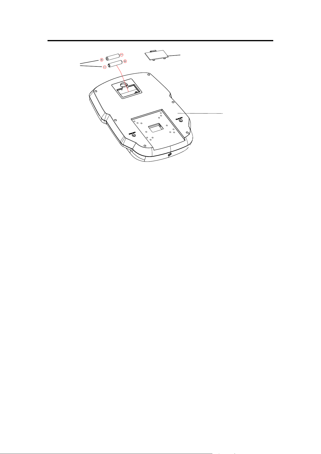
BATTERY INSTALLATION & REPLACEMENT
1
BATTERY INSTALLATION
1. Take out 2 AA batteries from computer box.
2. Press the buckle of battery cover on the Computer (No. 1), then remove battery
cover.
3. Install 2 AA batteries into the battery case on the back of the Computer (No. 1).
Pay attention to the battery + and - poles before installing.
4. Press the buckle of battery cover, then put the battery cover back to the back of the
Computer (No. 1).
The installation is complete!
BATTERY REPLACEMENT
1. Press the buckle of battery cover on the back of the Computer (No. 1), then
remove battery cover.
2. Remove the 2 old AA batteries in the battery case and install 2 new AA batteries
into the battery case on the back of the Computer (No. 1). Pay attention to the
battery + and - poles before installing.
3. Press the buckle of battery cover, then put the battery cover back to the back of the
Computer (No. 1).
The replacement is complete!
BATTERY DISPOSAL
Dispose the batteries according to the laws and regulations of your local region.
Some batteries maybe recycled. When disposing or recycling, do not mix battery
types.
Battery
Version 3.1
Battery Cover