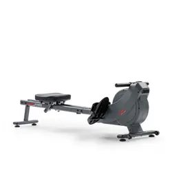
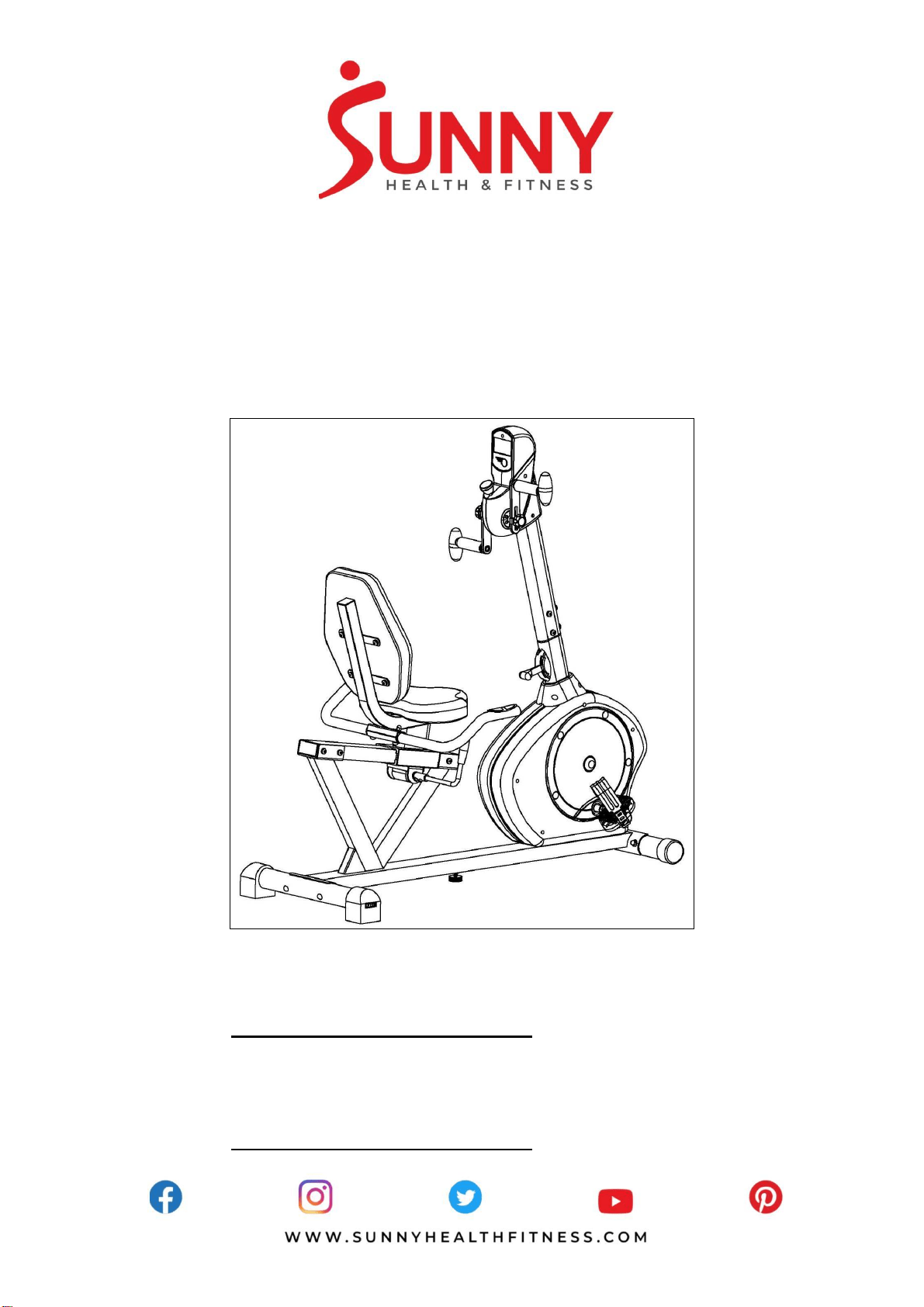
RECUMBENT BIKE WITH ARM
EXERCISER
SF-RB4631
USER MANUAL
English, Page 7~12 IMPORTANT! Please retain owner’s manual for maintenance and adjustment
instructions. Your satisfaction is very important to us, PLEASE DO NOT
RETURN UNTIL YOU HAVE CONTACTED US:
[email protected] or 1-877-90SUNNY (877-907-8669).
Español, Page 13~18 ¡IMPORTANTE! Conserve el manual del propietario para las instrucciones
de mantenimiento y ajuste. Su satisfacción es muy importante para nosotros,
NO DEVUELVA HASTA HABERNOS CONTACTADO:
[email protected] o 1- 877 - 90SUNNY (877-907-8669).

1
IMPORTANT SAFETY INFORMATION
We thank you for choosing our product. To ensure your safety and health, please use this
equipment correctly. It is important to read this entire manual before assembling and using the
equipment. Safe and effective use can only be achieved if the equipment is assembled,
maintained and used properly. It is your responsibility to ensure that all users of the equipment are
informed of all warnings and precautions.
1. Before starting any exercise program you should consult your physician to determine if you
have any medical or physical conditions that could put your health and safety at risk, or prevent
you from using the equipment properly. Your physician’s advice is essential if you are taking
medication that affects your heart rate, blood pressure or cholesterol level.
2. Be aware of your body’s signals. Incorrect or excessive exercise can damage your health. Stop
exercising if you experience any of the following symptoms: pain, tightness in your chest,
irregular heartbeat, shortness of breath, lightheadedness, dizziness or feelings of nausea. If
you do experience any of these conditions, you should consult your physician before continuing
with your exercise program.
3. Keep children and pets away from the equipment. The equipment is designed for adult use
only.
4. Use the equipment on a solid, flat level surface with a protective cover for your floor or carpet.
To ensure safety, the equipment should have at least 4 feet (1.2 M) of free space all around it.
5. Ensure that all nuts and bolts are securely tightened before using the equipment. The safety of
the equipment can only be maintained if it is regularly examined for damage and/or wear and
tear.
6. Always use the equipment as indicated. If you find any defective components while assembling
or checking the equipment, or if you hear any unusual noises coming from the equipment
during exercise, discontinue use of the equipment immediately and do not use until the
problem has been rectified.
7. Wear suitable clothing while using the equipment. Avoid wearing loose clothing that may
become entangled in the equipment.
8. Do not place fingers or objects into the moving parts of the equipment
9. The maximum weight capacity of this unit is 350 pounds (160 KG).
10. The equipment is not suitable for therapeutic use.
11. Use caution when lifting and moving the equipment. Always use proper lifting technique and
seek assistance if necessary.
12. Your product is intended for use in cool, dry conditions. You should avoid storage in extreme
cold, hot or damp areas as this may lead to corrosion and other related problems.
13. This equipment is designed for indoor and home use only! It is not intended for commercial
use!

2
INFORMACIÓN IMPORTANTE DE SEGURIDAD
Gracias por haber elegido nuestro producto. Para garantizar su seguridad y salud, utilice este
equipo correctamente. Es importante que lea todo el manual antes de instalar y usar el equipo.
Solo se puede archivar un uso seguro y eficaz del equipo si se instala, mantiene y utiliza
correctamente. Es su responsabilidad asegurarse de que todos los usuarios de los equipos
conozcan todas las advertencias y precauciones.
1. Antes de comenzar algún programa de ejercicios, deberá consultar con su médico para
determinar si tiene alguna condición médica o física que pudiera poner en riesgo su salud y
seguridad o que pudiera impedir que utilice correctamente el equipo. Es importante que reciba
las recomendaciones de su médico en caso de que esté tomando un medicamento que afecte
su ritmo cardíaco, presión arterial o nivel de colesterol.
2. Esté atento a las señales que le envía su cuerpo. Ejercitarse incorrecta o excesivamente
puede dañar su salud. Deje de hacer ejercicio si experimenta alguno de los siguientes
síntomas: dolor, opresión en el pecho, latidos cardíacos irregulares, extrema falta de aire,
sensación de desmayo, mareos o sensación de náuseas. Si presenta alguna de esas
condiciones, deberá consultar con su médico antes de continuar con su programa de
ejercicios.
3. Mantenga el equipo lejos del alcance de niños y mascotas. El equipo está diseñado para el
uso exclusivo de adultos.
4. Utilice el equipo en una superficie plana y sólida con una cubierta protectora para su piso o
alfombra. Para garantizar su seguridad, el equipo debe tener por lo menos 4 pies (120CM) de
espacio libre a su alrededor.
5. Asegúrese de que todas las tuercas y pernos estén bien ajustados antes de usar el equipo.
Solo puede conservarse la seguridad del equipo si se inspecciona regularmente para detectar
daños o desgaste.
6. Siempre utilice el equipo como se indica. Si encuentra algún componente defectuoso mientras
instala o revisa el equipo, o si escucha ruidos extraños que provienen de este mientras se
ejercita, deje de utilizarlo inmediatamente y no lo utilice hasta que el problema se haya
corregido.
7. Use ropa adecuada cuando utilice el equipo. Evite usar ropa suelta que pueda enredarse en el
equipo.
8. No coloque los dedos u objetos en las partes móviles del equipo.
9. La capacidad de peso máximo de esta unidad es de 350 libras (160KG).
10. El equipo no es adecuado para uso terapéutico.
11. Debe cuidarse al levantar y mover el equipo a fin de que no se dañe la espalda. Siempre utilice
la técnica de levantamiento adecuada y pida ayuda en caso de que sea necesario.
12. Su producto está diseñado para su uso en condiciones frescas y secas. Usted debe evitar el
almacenamiento en zonas extremadamente frías, calientes o húmedas, ya que pueden
provocar corrosión y otros problemas relacionados.
13. ¡Este equipo está diseñado para el uso exclusivo en la casa y en interiores! ¡No es para uso
comercial!
3
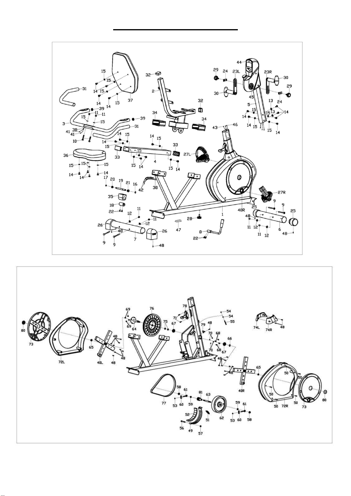
EXPLODED DIAGRAM
4
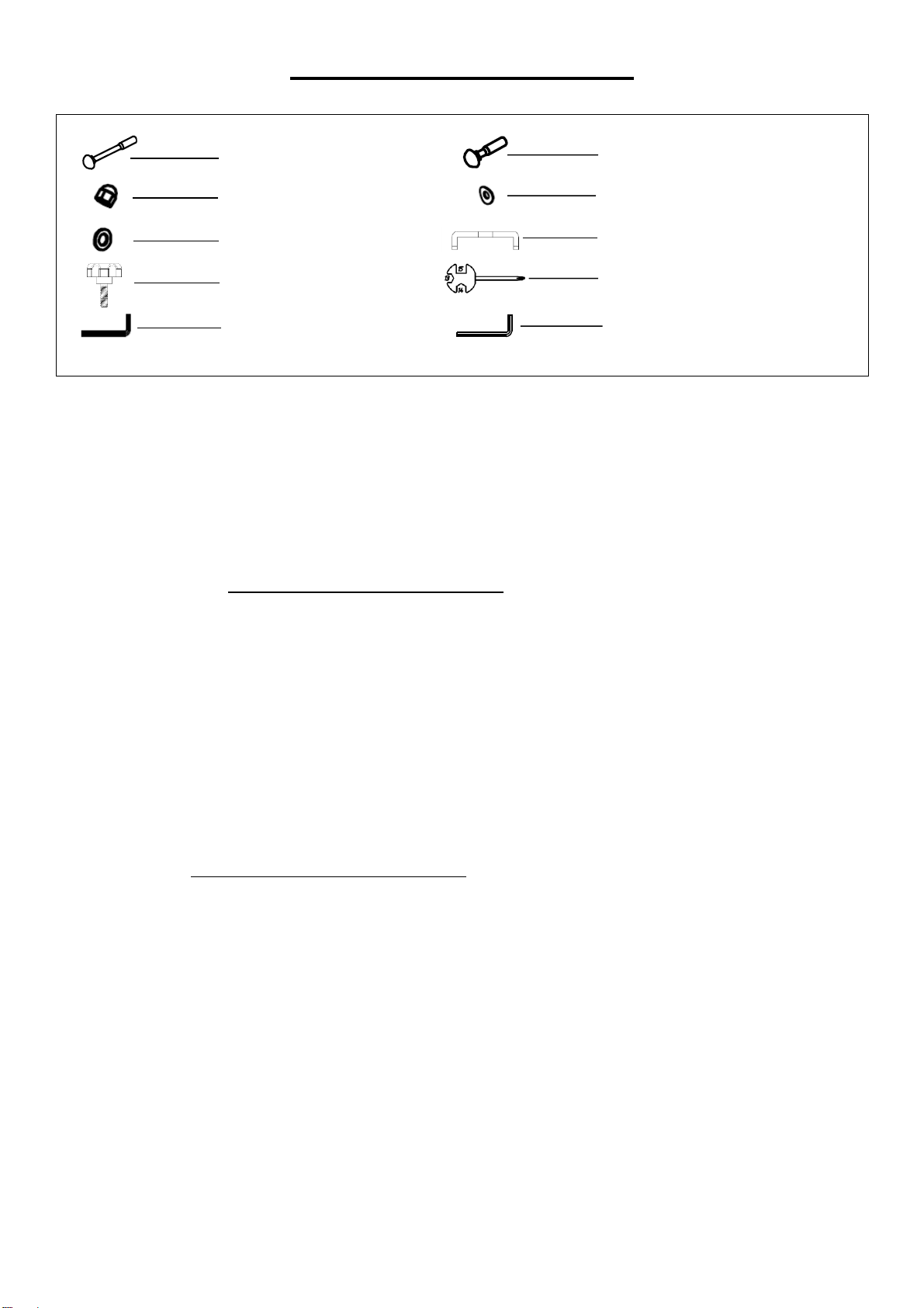
HARDWARE PACKAGE
Ordering Replacement Parts (U.S. and Canadian Customers only)
Please provide the following information in order for us to accurately identify the part(s) needed:
✓ The model number (found on cover of manual)
✓ The product name (found on cover of manual)
✓ The part number found on the “EXPLODED DIAGRAM” and “PARTS LIST” (found near the
front of the manual)
Please contact us at [email protected] or 1- 877 – 90SUNNY (877-907-8669).
Pedido de piezas de repuesto (solo para clientes de EE. UU. y Canadá)
Proporcione la siguiente información para que podamos identificar con precisión las piezas
necesarias:
✓ El número de modelo (se encuentra en la portada del manual).
✓ El nombre del producto (se encuentra en la portada del manual).
✓ El número de pieza que se encuentra en el “ESQUEMA DE LAS PIEZAS” y en la “LISTA
DE PIEZAS” (se encuentra al principio del manual).
Contáctenos en [email protected] o 1- 877 - 90SUNNY (877-907-8669).
#9 M8*L73 4PCS
#10 M8*L45 2PCS
#11 M8 6PCS
#12 Ф8.2*2*Ф19*R30 4PCS
#15 D8*1.5*Ф16 2PCS
#24 2PCS
#29 2PCS
#82 S13-14-15 1PC
#83 S5 1PC
#84 S6 1PC

5
PARTS LIST
No.
Description
Spec.
Qty.
No.
Description
Spec.
Qty.
1
Main Frame
1
43
Sensor Wire
1
2
Seat Tube
1
44
Computer
1
3
Handlebar
1
45
Connecting Axle
1
4
Slide Rail
1
46
Pulse Sensor Wire 2
2
5
Handlebar Post
1
47
Square Plug
60*30*1.5
1
6
Front Stabilizer
1
48
Cross Pan Head
Self-Drilling Screw
ST4.2*18
23
7
Rear Stabilizer
1
49
Magnet Board
Connection
1
8
Adjustment Handle
1
50
Cross Pan Head
Self-Drilling Screw
ST4.2*30
5
9
Square Neck Bolt
M8*L73
4
51
Spring
1
10
Square Neck Bolt
M8*L45
2
52
Magnet
8
11
Ball Cap Nut
M8
6
53
Nut
M6
2
12
Arc Washer
Ф8.2*2*Ф19*R30
4
54
Nut
M5
2
13
Arc Washer
d8*R20
2
55
Hex Bolt
M5*60
1
14
Hex Pan Head Screw
M8*16
20
56
Hex Bolt
M8*L60*120
1
15
Washer
D8*1.5*Ф16
20
57
Nylon Nut
M8
1
16
Spring Stop Collar
D12
1
58
Flange Nut
M10*1
2
17
Spring Stop Collar
D10
1
59
Cone Thin Nut
M10*1*H5
2
18
Eccentric Gear
1
60
Adjustable U Washer
2
19
Axle
1
61
Adjustable Screw
2
20
Small Alloy Bushing
1
62
Fly Wheel
1
21
Big Alloy Bushing
1
63
Fly Wheel Axle
1
22
Hex Socket Cap
Screw
M6*10
4
64
Middle Axle
1
23L/R
Rotating Handle
1pr.
65
Flange Nut
M10*1.25
2
24
U Shape Board
2
66
Spring Shield
1
25
Wheeled End Cap
2
67
Bearing
6003RZ
2
26
End Cap
2
68
Hex Socket Head
Cap Screw
M6*15
4
27L/R
Pedal
1pr.
69
Nylon Nut
M6
4
28
Adjustable Pad
1.
70
Spring Washer
D6
4
29
Knob
2
71
Cross Pan Head
Screw
M5*12
2
30
Oval Handle
2
72L/R
Belt Cover
1pr.
31
Foam Grip
2
73
Disc
2
32
Square Plug
38*38*1.5
2
74L/R
Front Tube Cover
1pr.
33
Square Plug
80*40*2
2
75
Central Axle Spacer
2
34
Bushing
2
76
Big Belt Pulley
1
35
Upper Holder Block
1
77
Belt
1
36
Seat
1
78
Tension Controller
1
37
Backrest
1
79
Sensor
1
38
Guide Line Hole Plug
2
80
Nut Cap
2
39
Round Tube Plug
2
81
Small Belt Pulley
1
40L/R
Crank
1pr.
82
Spanner
S13-14-15
1
41
Pulse Wire
2
83
Allen Wrench
S5
1
42
Pulse Sensor Wire 1
2
84
Allen Wrench
S6
1

6
LISTA DE PIEZAS
n.°
DESCRIPCIÓN
ESPEC.
CANT.
n.°
DESCRIPCIÓN
ESPEC.
CANT.
1
Estructura Principal
1
43
Cable del Sensor
1
2
Tubo del Asiento
1
44
Computadora
1
3
Manubrio
1
45
Eje de Conexión
1
4
Riel de Deslizamiento
1
46
Cable del Sensor de
Pulso 2
2
5
Poste del Manubrio
1
47
Clavija Cuadrada
60*30*1.5
1
6
Estabilizador
Delantero
1
48
Tornillo Autorroscante
ST4.2*18
23
7
Estabilizador Trasero
1
49
Tablero Magnético de
Conexión
1
8
Manija de Ajuste
1
50
Tornillo Autorroscante
ST4.2*30
5
9
Perno de Cuello
Cuadrada
M8*L73
4
51
Resorte
1
10
Perno de Cuello
Cuadrada
M8*L45
2
52
Imán
8
11
Tuerca Ciega
M8
6
53
Tuerca
M6
2
12
Arandela
Ф8.2*2*Ф19*R30
4
54
Tuerca
M5
2
13
Arandela
d8*R20
2
55
Perno Hexagonal
M5*60
1
14
Tornillo de Cabeza
Hexagonal
M8*16
20
56
Perno Hexagonal
M8*L60*120
1
15
Arandela
D8*1.5*Ф16
20
57
Tuerca de Nylon
M8
1
16
Tope de Resorte
D12
1
58
Tuerca
M10*1
2
17
Tope de Resorte
D10
1
59
Tuerca
M10*1*H5
2
18
Engranaje
1
60
Arandela Ajustable de
Forma U
2
19
Eje
1
61
Tornillo Ajustable
2
20
Buje de Aleación
Pequeña
1
62
Volante de Inercia
1
21
Buje de Aleación
Grande
1
63
Eje de Volante de
Inercia
1
22
Tornillo de Cabeza
Hexagonal
M6*10
4
64
Eje Medio
1
23L/R
Manija Giratoria
1par.
65
Tuerca
M10*1.25
2
24
Tablero en Forma de
U
2
66
Cubierta de Resorte
1
25
Tapa de Extremo con
Ruedas
2
67
Cojinete
6003RZ
2
26
Tapa de Extremo
2
68
Tornillo
M6*15
4
27L/R
Pedal
1par.
69
Tuerca de Nylon
M6
4
28
Nivelador
1.
70
Arandela de Presión
D6
4
29
Perilla
2
71
Tornillo
M5*12
2
30
Manija Oval
2
72L/R
Cubierta de Cinturon
1par.
31
Agarre de Espuma
2
73
Disco
2
32
Clavija Cuadrada
38*38*1.5
2
74L/R
Cubierta Delantera de
Tubo
1par.
33
Clavija Cuadrada
80*40*2
2
75
Espaciador del Eje
Central
2
34
Buje
2
76
Polea Grande de Correa
1
35
Bloque de Soporte
Superior
1
77
Correa
1
36
Asiento
1
78
Controlador de Tensión
1
37
Respaldo
1
79
Sensor
1
38
Clavija
2
80
Tapa de Tuerca
2
39
Clavija Redondo
2
81
Polea Pequeña de
Correa
1
40L/R
Biela
1par.
82
Llave Inglesa
S13-14-15
1
41
Cable del Pulso
2
83
Llave Allen
S5
1
42
Cable del Sensor de
Pulso 1
2
84
Llave Allen
S6
1
7
ASSEMBLY INSTRUCTIONS
We value your experience using Sunny Health and Fitness products. For assistance with parts or
(877-907-8669).
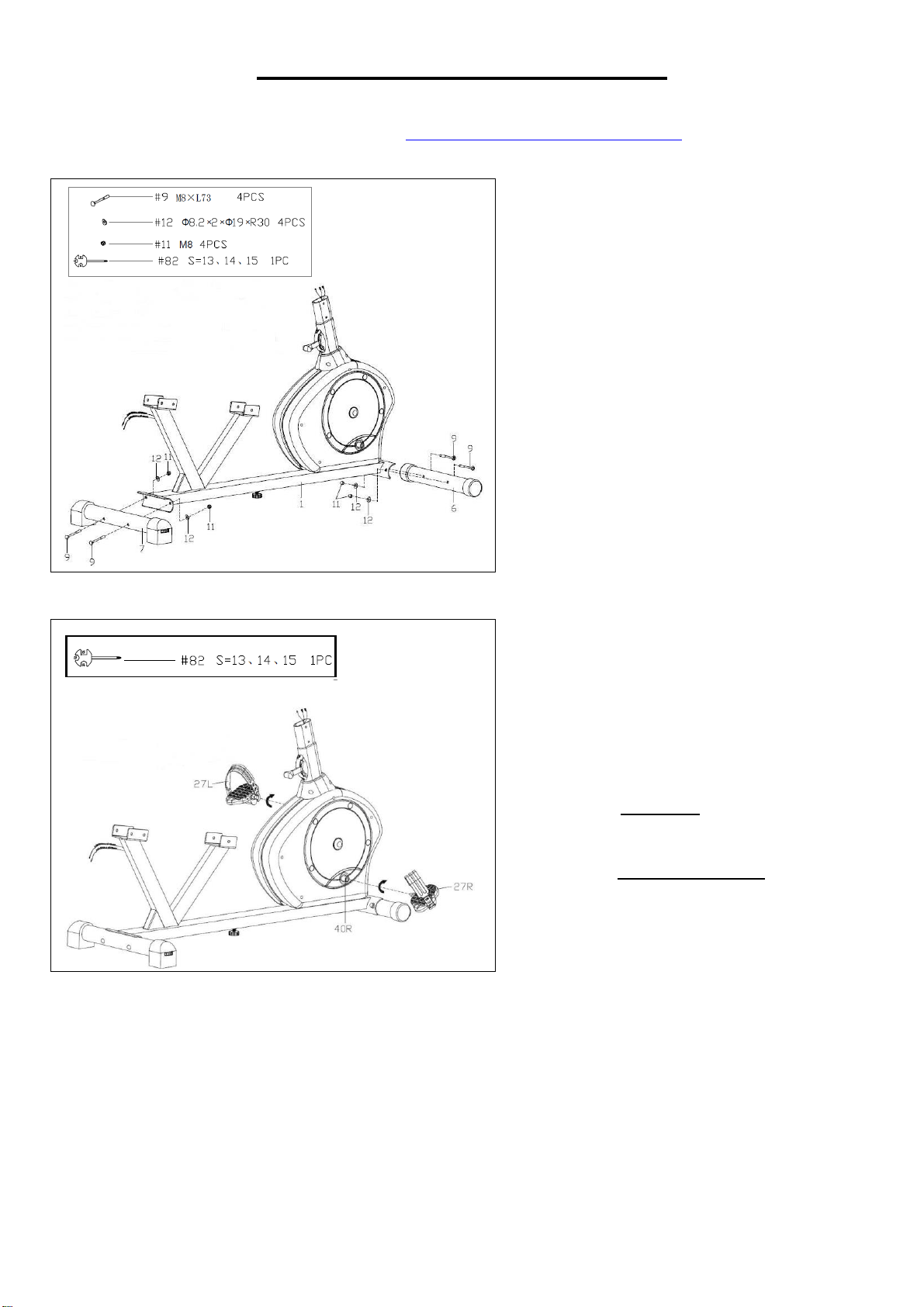
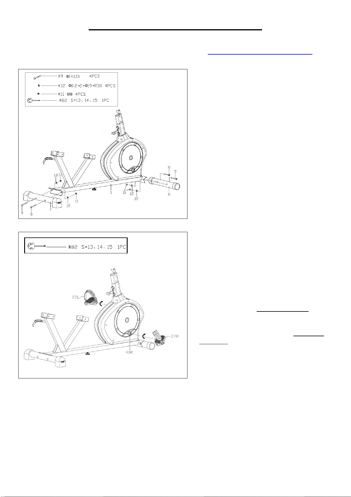
STEP 1
Attach the Front Stabilizer (No. 6) and
the Rear Stabilizer (No. 7) to the Main
Frame (No. 1) with the 4 Square Neck
Bolts (No. 9), 4 Arc Washers (No. 12)
and 4 Ball Cap Nuts (No. 11) using
Spanner (No. 82).
STEP 2
Attach the Pedals (No. 27L/R) to the
Cranks (No. 40L/R) using the Spanner
(No. 82).
NOTE: Make sure to attach Right
Pedal (No. 27R), marked (R), to the
Right Crank (No. 40R) and should be
tightened clockwise. Attach the Left
Pedal (No. 27L), marked (L), to the
Left Crank (No.40L). It should be
tightened counter-clockwise. Attaching
the Pedals (No. 27L/R) to the wrong
Cranks (No. 40L/R) or turning it the
wrong direction can damage the
Cranks (No. 40L/R).
8
We value your experience using Sunny Health and Fitness products. For assistance with parts or
(877-907-8669).
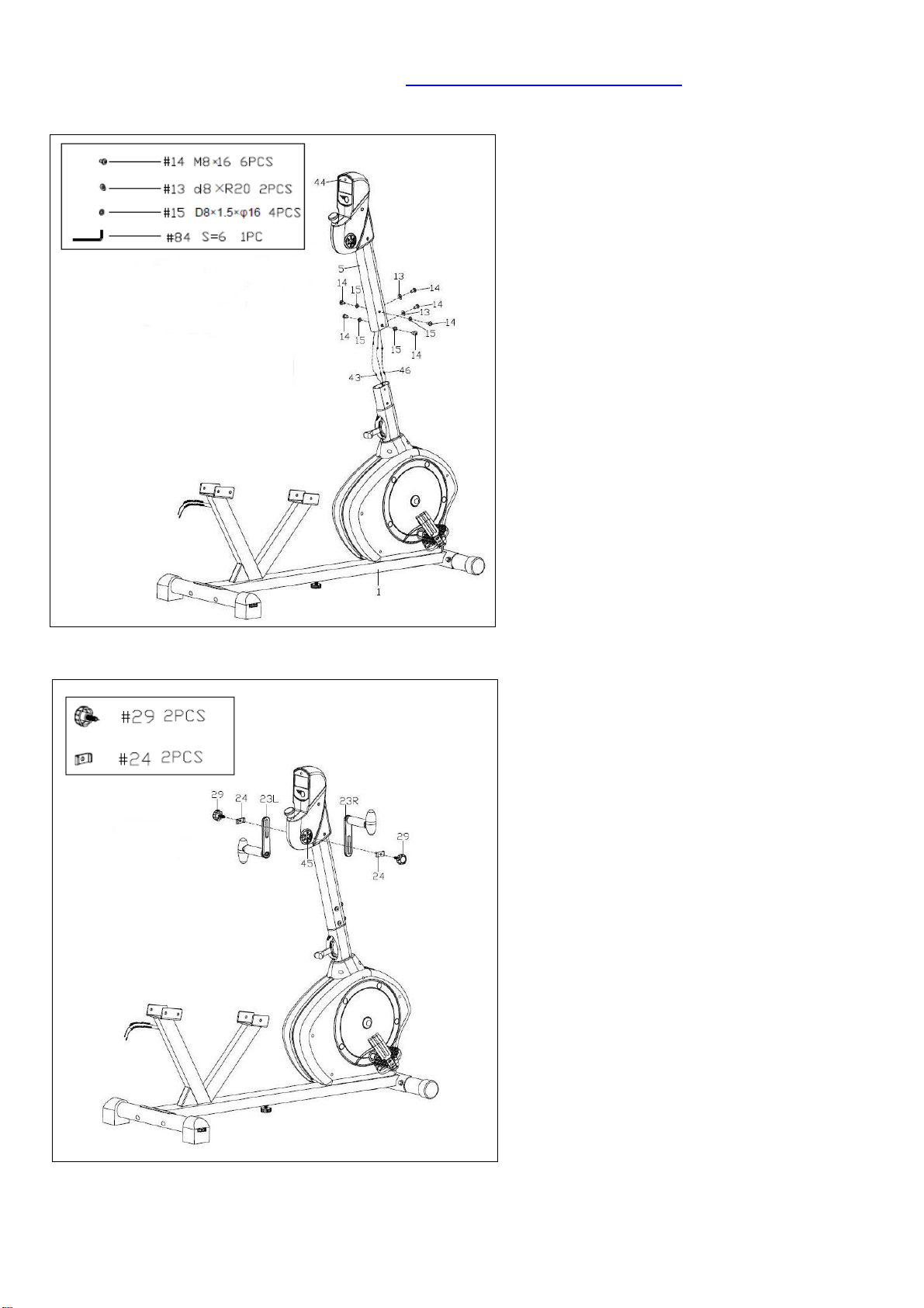
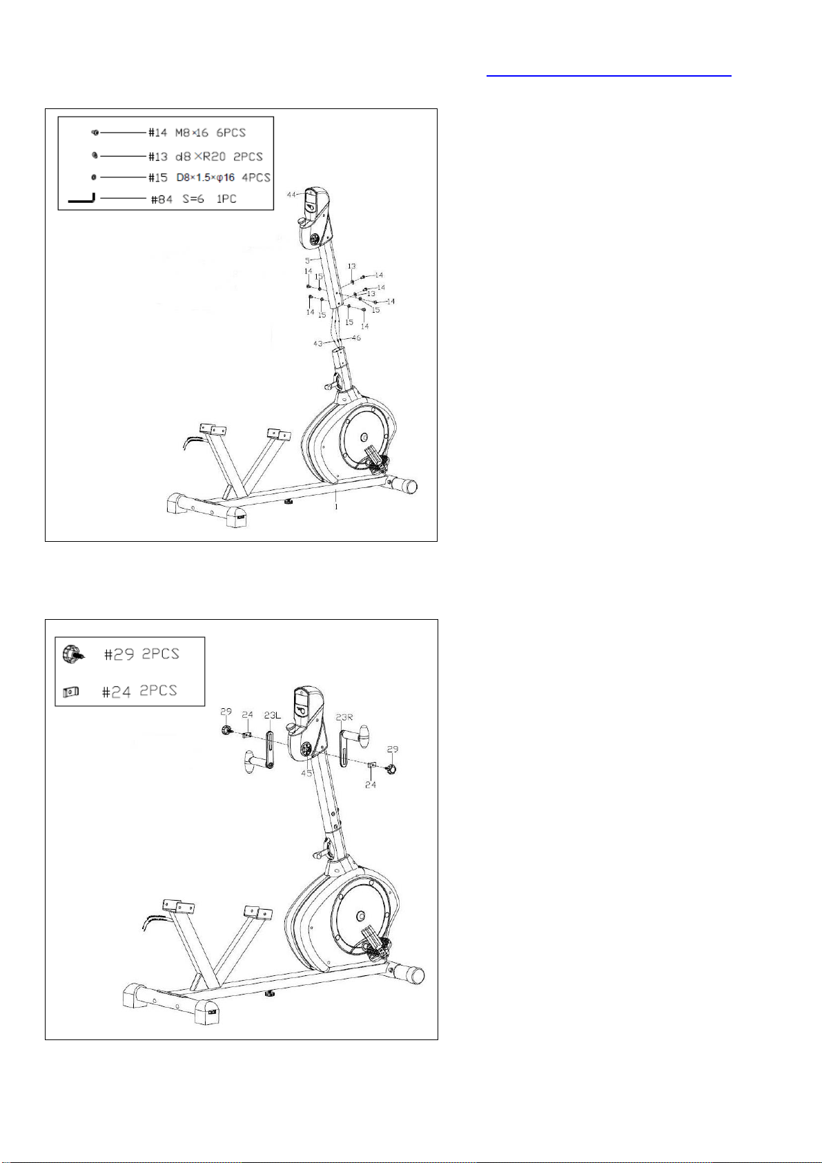
STEP 3
First, remove the preassembled 6 Hex
Pan Head Screws (No. 14), 2 Arc
Washers (No. 13) and 4 Washers (No.
15) from the Main Frame (No. 1) using
Allen Wrench (No. 84). Then connect
the 2 Pulse Sensor Wires 2 (No. 46)
and Sensor Wire (No. 43) with the
wires of the Computer (No. 44). Then
attach the Handlebar Post (No. 5) to
the Main Frame (No. 1) with the 6 Hex
Pan Head Screws (No. 14), 2 Arc
Washers (No. 13) and 4 Washers (No.
15) that were just removed. Tighten
and secure with Allen Wrench (No.
84).
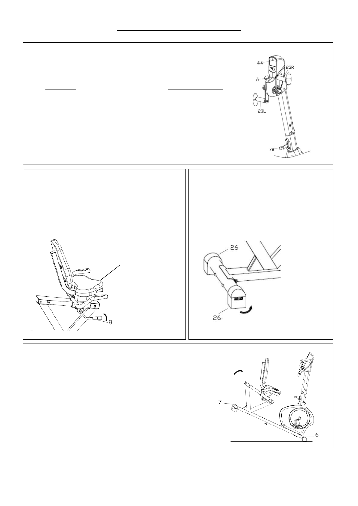
STEP 4
Attach the Rotating Handles (No.
23L/R) to the Connecting Axle (No.
45) with 2 Knobs (No. 29) and 2 U
Shape Boards (No. 24).
Note: You can adjust the position of the
Rotating Handles (No. 23L/R) by
loosening the 2 Knobs (No. 29),
moving the Rotating Handles (No.
23L/R) to desired position, and then
tightening the 2 Knobs (No. 29).
9
We value your experience using Sunny Health and Fitness products. For assistance with parts or
(877-907-8669).
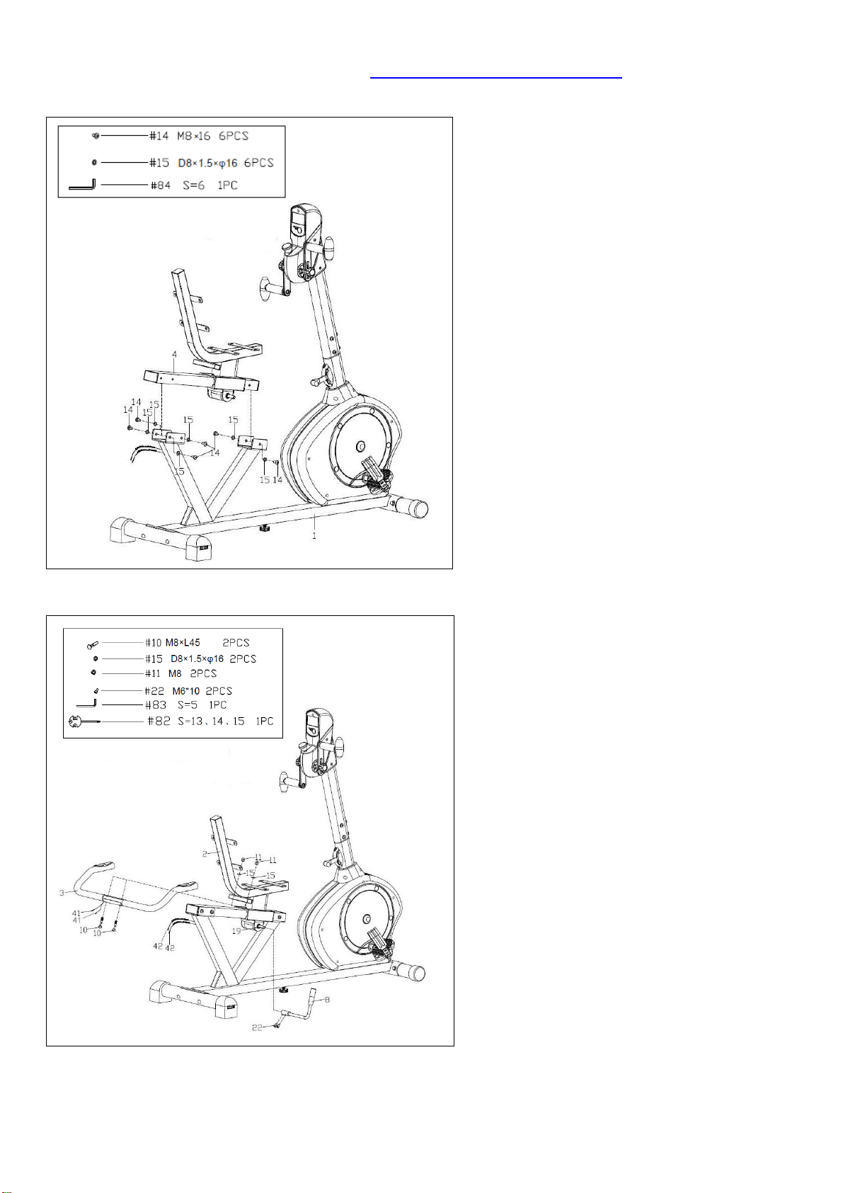
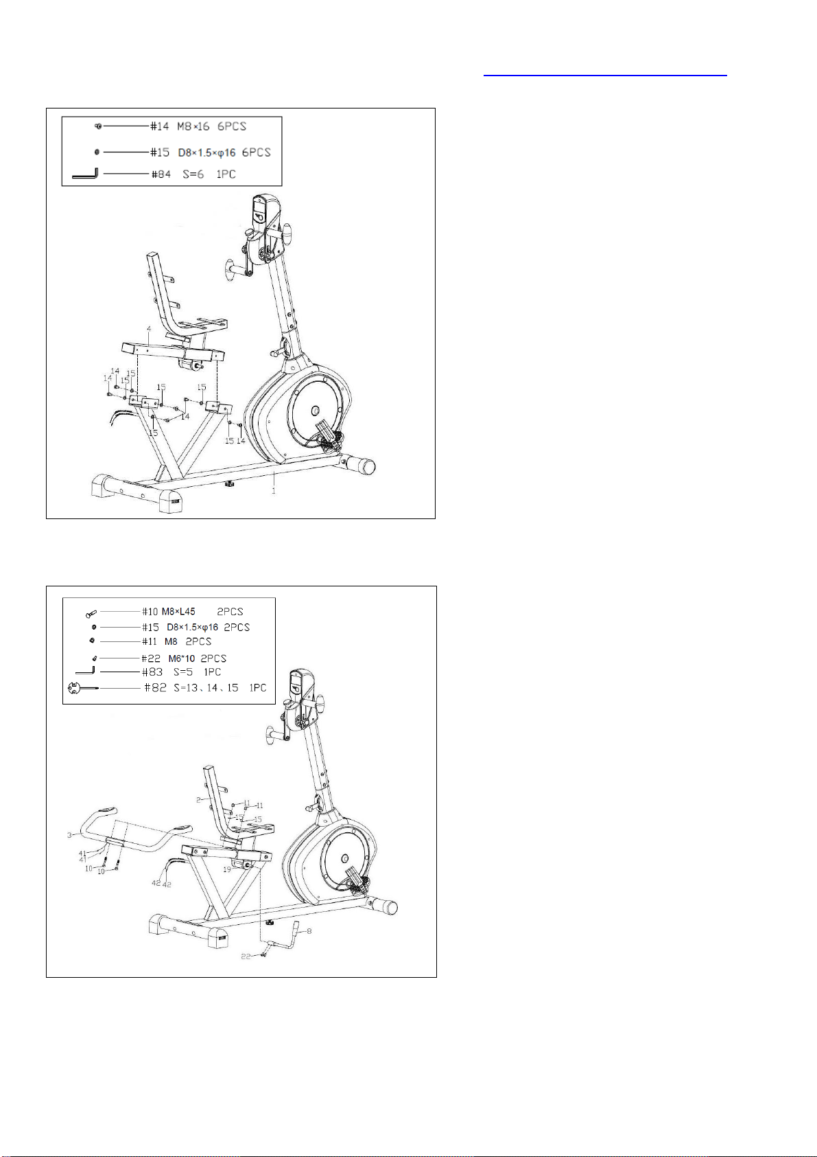
STEP 5
First, remove the preassembled 6 Hex
Pan Head Screws (No. 14) and 6
Washers (No. 15) from the Slide Rail
(No. 4) using Allen Wrench (No. 84).
Then attach the Slide Rail (No. 4) to
the Main Frame (No. 1) with 6 Hex
Pan Head Screws (No. 14) and 6
Washers (No. 15) that were just
removed. Tighten and secure with
Allen Wrench (No. 84).
STEP 6
First, remove the preassembled 2 Hex
Socket Cap Screws (No. 22) from the
Axle (No. 19). Then attach the
Adjustment Handle (No. 8) to the
Axle (No. 19), and secure tightly with
the 2 Hex Socket Cap Screws (No.
22) that were just removed. Tighten and
secure with Allen Wrench (No. 83).
Make sure the Adjustment Handle
(No. 8) is pointing up.
Set the Handlebar (No. 3) onto the
Seat Tube (No. 2), and secure tightly
with the 2 Square Neck Bolts (No. 10),
2 Washers (No. 15) and 2 Ball Cap
Nuts (No. 11) using Spanner (No. 82).
Connect the 2 Pulse Wires (No. 41)
with the 2 Pulse Sensor Wires 1 (No.
42).
10
We value your experience using Sunny Health and Fitness products. For assistance with parts or
(877-907-8669).
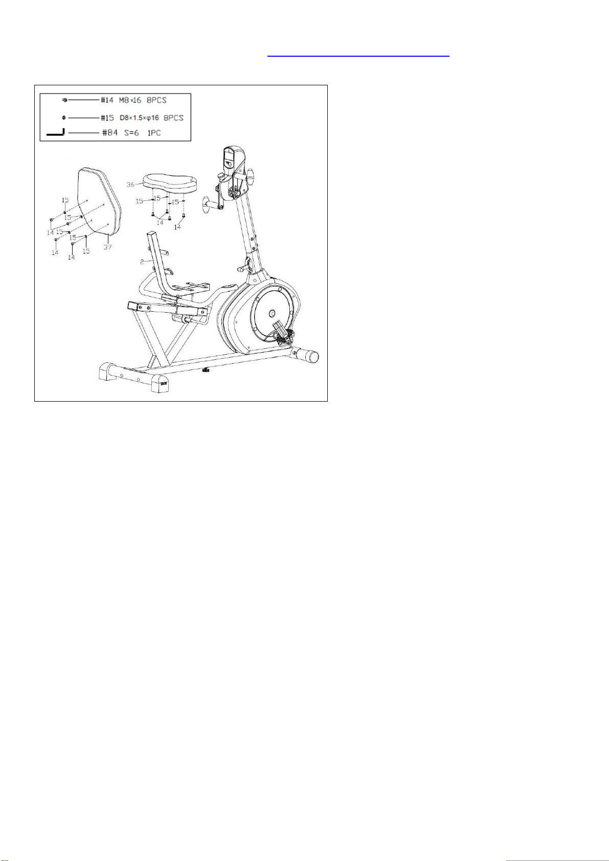
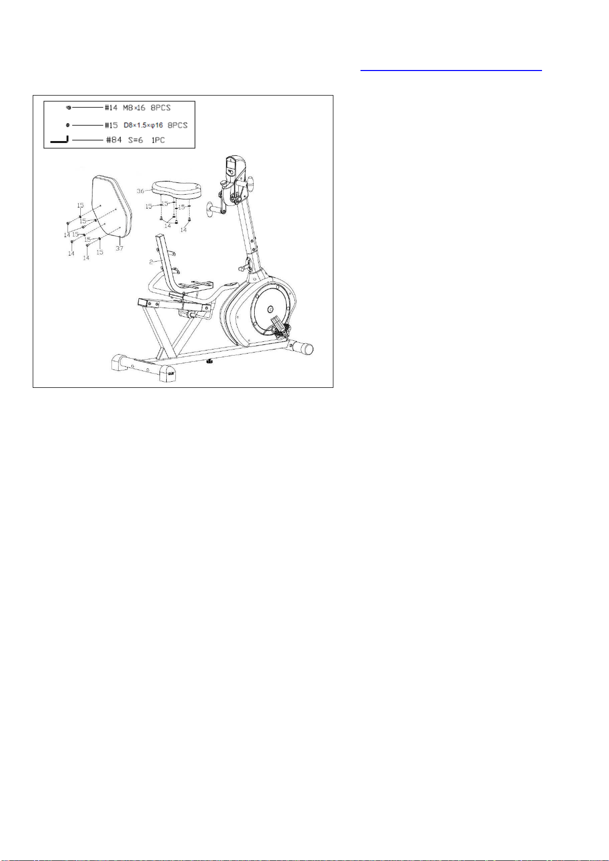
STEP 7
Remove the preassembled 4 Hex Pan
Head Screws (No. 14) and 4 Washers
(No. 15) from the Backrest (No. 37)
using Allen Wrench (No. 84). Then
attach the Backrest (No. 37) to the
Seat Tube (No. 2) tightly with 4 Hex
Pan Head Screws (No. 14) and 4
Washers (No. 15) that were just
removed. Tighten and secure with
Allen Wrench (No. 84).
Remove the preassembled 4 Hex Pan
Head Screws (No. 14) and 4 Washers
(No. 15) from the Seat (No. 36) using
Allen Wrench (No. 84). Then attach
the Seat (No. 36) to the Seat Tube (No.
2) tightly with 4 Hex Pan Head Screws
(No. 14) and 4 Washers (No. 15) that
were just removed. Tighten and secure
with Allen Wrench (No. 84).
Assembly is now complete!
11
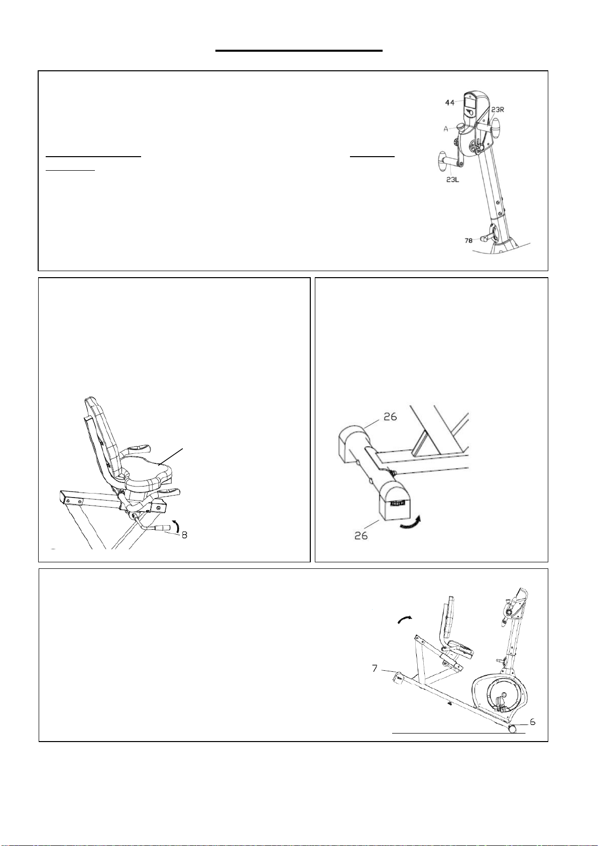
ADJUSTMENT GUIDE
13
ADJUSTING THE SEAT POSITION
To move the Seat (No. 36) forward or backward
while seated on the bike, pull the Adjustment
Handle (No. 8) towards you. Move the Seat
(No. 36). Push the Adjustment Handle (No. 8)
forward to secure.
ADJUSTING THE LEVEL
If at any point the bike does not feel level,
you can adjust the dials located on the
side of the rear End Caps (No. 26).
ADJUSTING THE TENSION
To adjust the tension of the Rotating Handles (No. 23L/R),
turn the Tension Knob A in front of the Computer (No. 44).
Turn clockwise (+) to increase the tension, counterclockwise (-)
to decrease the tension.
To adjust the tension of the bike, move Tension Controller
(No. 78). 1 is the lowest tension. 8 is the highest tension.
MOVING THE BIKE
Lift the bike by the Rear Stabilizer (No. 7) until the
wheels on the Front Stabilizer (No. 6) touch the floor.
You can now move the bike to your desired location with
ease.
36
12
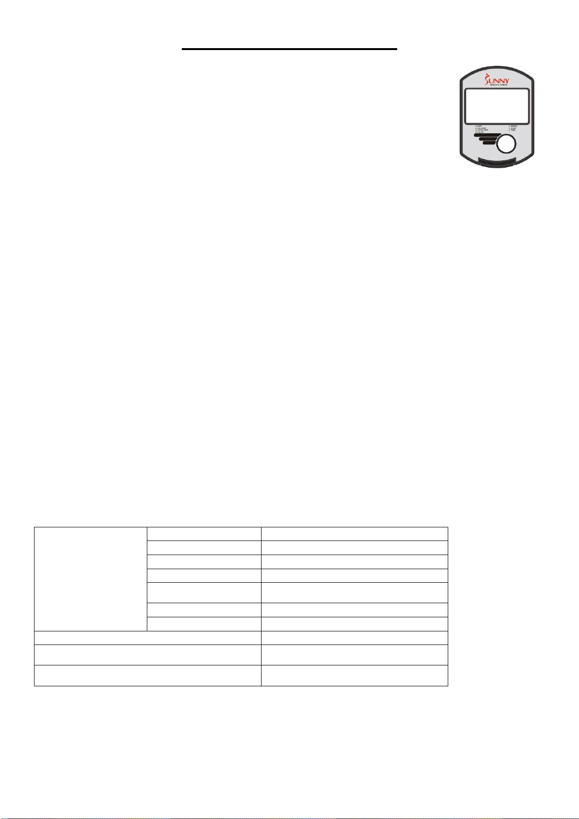
EXERCISE COMPUTER
MODE: Press to select function.
Press and hold for 2 seconds to reset all values except TOTAL DIST.
FUNCTIONS AND OPERATIONS:
1. SCAN: Press MODE button until “▼” appears at SCAN Position. Computer
will rotate through all the 6 functions: Time, Speed, Distance, Calorie, Total
Distance, and Pulse. Each function will display for 6 seconds.
2. TIME: Counts the total time from exercise start to end.
3. SPEED: Displays current speed.
4. DIST: Count the distance from exercise start to end.
5. CALORIES (CAL): Counts the total calories from exercise start to the end.
6. TOTAL DIST (ODO): Counts the total distance after installing the batteries.
7. PULSE: Press MODE button until “▼” appears at PULSE. Before measuring your pulse rate,
place both your palms on the contact pads and the computer will show your current heartbeat
rate in beats per minute (BPM) after 3~4 seconds.
Remark: During the process of pulse measurement, the measurement value may be higher
than virtual pulse rate during the first 2~3 seconds, then it will return to normal level.
To ensure testing accuracy, it is suggested that user test pulse while not pedaling. The
measurement value cannot be regarded as the basis for medical treatment.
8. AUTO ON/OFF & AUTO START/STOP: Without any signal for 4 minutes, the power will turn
off automatically.
BATTERY
If there is a problem with the display, try replacing the batteries. When changing the batteries,
change both of them. Do not mix battery types. Do not mix old and new batteries. Dispose of
batteries according to your state and local guidelines.
SPECIFICATIONS
FUNCTION
Auto Scan
Every 6 seconds
Running Time
00:00 ~ 99:59 (Minute: Second)
Current Speed
Max is 99.9 MILE/H
Trip Distance
0.0 ~ 99.99 MILE
Calories
0.0 ~ 999.9 Kcal
Total Distance
0.0 ~ 999.9 MILE
Pulse Rate
40-240 BPM
Battery Type
2 pcs of SIZE-AA and UM3
Operating Temperature
0℃ ~ +40℃ (32℉~ 104℉)
Storage Temperature
-10℃ ~ +60℃ (14℉~ 140℉)
Version 1.11
13
INSTRUCCIONES DE ARMADO
Valoramos su experiencia con los productos de Sunny Health and Fitness. Para obtener ayuda con
1-877-90SUNNY (877-907-8669).
PASO 1:
Conecte el Estabilizador Delantero
(No. 6) y el Estabilizador Trasero (No.
7) al Estructura Principal (No. 1) con
los 4 Pernos de Cuello Cuadrada
(No. 9), 4 Arandelas (No. 12) y 4
Tuercas Ciega (No. 11) usando la
Llave Inglesa (No. 82).
PASO 2:
Conecte los Pedales (No. 27L/R) a la
Bielas (No. 40L/R) usando la Llave
Inglesa (No. 82).
NOTA: Asegúrese de colocar el Pedal
Derecho (No. 27R), marcado (R), en la
Biela Derecha (No. 40R) y debe
apretarse girando hacia la derecha. Fije
el Pedal Izquierdo (No. 27L), marcado
(L), a la Biela Izquierda (No.40L).
Debe apretarse girando hacia la
izquierda. Si coloca el Pedals (No.
27L/R) en la Bielas (No. 40L/R)
incorrecta o lo gira en la dirección
equivocada, puede dañar la Bielas
(No. 40L/R).
14
Valoramos su experiencia con los productos de Sunny Health and Fitness. Para obtener ayuda con
1-877-90SUNNY (877-907-8669).
PASO 3:
Primero, retire los 6 Tornillos de Cabeza
Hexagonal (No. 14) premontados, 2
Arandelas (No. 13) y 4 Arandelas (No.
15) del Estructura Principal (No. 1)
usando una Llave Allen (No. 84). Luego,
conecte los 2 Cables del Sensor de
Pulso 2 (No. 46) y el Cable del Sensor
(No. 43) con los cables de la
Computadora (No. 44). Luego, fije el
Poste del Manubrio (No. 5) al
Estructura Principal (No. 1) con los 6
Tornillos de Cabeza Hexagonal (No. 14),
2 Arandelas (No. 13) y 4 Arandelas (No.
15) usando Llave Allen (No. 84).
PASO 4:
Fija las Manijas Giratorias (No. 23L/R) al
Eje de Conexión (No. 45) con 2 Perillas
(No. 29) y 2 Tableros en Forma de U
(No. 24).
Nota: Puede ajustar la posición de las
Manijas Giratorias (No. 23L/R) aflojando
2 Perillas (No. 29), moviendo las Manijas
Giratorias (No. 23L/R) a la posición
deseada , y luego apretando la 2 Perillas
(No. 29).
15
Valoramos su experiencia con los productos de Sunny Health and Fitness. Para obtener ayuda con
1-877-90SUNNY (877-907-8669).
PASO 5:
Primero, retire los 6 Tornillos de Cabeza
Hexagonal (No. 14) premontados y 6
Arandelas (No. 15) del Riel de Deslizante
(No. 4) usando una Llave Allen (No. 84).
Luego, fije el Riel de Deslizante (No. 4) al
Estructura Principal (No. 1) con 6
Tornillos de Cabeza Hexagonal (No. 14) y
6 Arandelas (No. 15) usando una Llave
Allen (No. 84).
PASO 6:
Primero, retire los 2 Tornillos de Cabeza
Hexagonal (No. 22) premontados del Eje
(No. 19). Luego fije la Manija de Ajuste
(No. 8) al Eje (No. 19), y asegure
firmemente con los 2 Tornillos de Cabeza
Hexagonal (No. 22) que se acaban de
quitar. Apriete y asegure con Llave Allen
(No. 83). Asegúrese de que la Manija de
Ajuste (No. 8) esté apuntando hacia
arriba.
Coloque el Manubrio (No. 3) en el Tubo
del Asiento (No. 2), y asegure firmemente
con los 2 Pernos de Cuello Cuadrada (No.
10), 2 Arandelas (No. 15) y 2 Tuercas
Ciega (No. 11) usando la Llave Inglesa
(No. 82). Conecte los 2 Cables del Pulso
(No. 41) con los 2 Cables del Sensor de
Pulso 1 (No. 42).
16
Valoramos su experiencia con los productos de Sunny Health and Fitness. Para obtener ayuda con
1-877-90SUNNY (877-907-8669).
PASO 7:
Retire los 4 Tornillos de Cabeza
Hexagonal (No. 14) premontados y 4
Arandelas (No. 15) del Respaldo (No.
37) con una Llave Allen (No. 84).
Luego fije el Respaldo (No. 37) al Tubo
del Asiento (No. 2) firmemente con 4
Tornillos de Cabeza Hexagonal (No.
14) y 4 Arandelas (No. 15) que se
acaban de quitar. Apriete y asegure con
Llave Allen (No. 84).
Retire los 4 Tornillos de Cabeza
Hexagonal (No. 14) y 4 Arandelas (No.
15) del Asiento (No. 36) con una Llave
Allen (No. 84). Luego fije el Asiento
(No. 36) al Tubo del Asiento (No. 2)
firmemente con 4 Tornillos de Cabeza
Hexagonal (No. 14) y 4 Arandelas (No.
15) que se acaban de quitar. Apriete y
asegure con Llave Allen (No. 84).
¡El armado ahora está completa!
17
AJUSTE DE LA POSICION DEL ASIENTO
Para mover el Asiento (No. 36) hacia adelante
o hacia atrás mientras está sentado en la
bicicleta, tire de la Manija de Ajuste (No. 8)
hacia usted. Mueve el Asiento (No. 36).
Empuje la Manija de Ajuste (No. 8) hacia
adelante para asegurarla.
GUÍA DE AJUSTE
AJUSTE DEL TENSION
Para ajustar la tensión de los Manijas Giratorias (No. 23L/R),
gire la Perilla de Tensión A frente al Computadora (No. 44).
Gira
hacia la derecha (+) para aumentar la tensión, gira hacia la
izquierda (-) para disminuir la tensión.
Para ajustar la tensión de la bicicleta, mueva el Controlador de
Tensión (No. 78).1 es la tensión más baja. 8 es la tensión más
alta.
AJUSTANDO EL NIVEL
Si en algún punto la bicicleta no se
siente nivelada, puede ajustar los discos
que se encuentran en el lado de las
Tapas del Extremo (No. 26).
MOVIENDO LA BICICLETA
Levante la bicicleta por el Estabilizador Trasero (No. 7)
hasta que las ruedas del Estabilizador Delantero (No.
6) toquen el piso. Ahora puede mover la bicicleta a la
ubicación deseada con facilidad.
36

18
MEDIDOR DE EJERCICIO
MODO: Presione para seleccionar la función.
Mantenga presionado durante 2 segundos para restablecer todos los valores
excepto DISTANCIA TOTAL (TOTAL DIST)
FUNCIONES Y OPERACIONES:
1. ESCANEAR (SCAN): presione el botón MODE hasta que aparezca “▼” en la
posición de ESCANEADO (SCAN). La computadora girará a través de las 6
funciones: Tiempo, Velocidad, Distancia, Calorías, Distancia total y Pulso. Cada
función se mostrará durante 6 segundos.
2. TIEMPO (TIME): cuenta el tiempo total desde el inicio hasta el final del ejercicio.
3. VELOCIDAD (SPEED): Muestra la velocidad actual.
4. DISTANCIA (DIST): Cuenta la distancia desde el inicio hasta el final del ejercicio.
5. CALORÍAS (CAL): Cuenta el total de calorías desde el inicio hasta el final.
6. DISTANCIA TOTAL (TOTAL DIST): Cuenta la distancia total después de instalar las baterías.
7. PULSO (PULSE): presione el botón MODO hasta que aparezca “▼” en PULSO (PULSE).
Antes de medir su pulso, coloque ambas palmas en los puntos de contacto y la computadora
mostrará su frecuencia cardíaca actual en pulsaciones por minuto (PPM) después de 3 a 4
segundos.
Observación: Durante el proceso de medición de pulso, el valor de medición puede ser más alto
que la frecuencia de pulso actual durante los primeros 2 a 3 segundos, luego regresará al nivel
normal.
Para garantizar la precisión de la prueba, se sugiere que el usuario pruebe el pulso mientras no
pedalea. El valor de medición no puede considerarse como la base para el tratamiento médico.
8. ENCENDIDO / APAGADO AUTOMÁTICO Y ARRANQUE / PARADA AUTOMÁTICOS: Sin
ninguna señal durante 4 minutos, la alimentación se apagará automáticamente.
BATERÍA
Si hay un problema con la pantalla, intente cambiar las pilas. Al cambiar las pilas, cambia las dos.
No mezcle tipos de pilas. No mezcle pilas viejas y nuevas. Deseche las baterías de acuerdo con
las regulaciones estatales y locales.
ESPECIFICACIONES
FUNCIÓN
Escaneo Automatico
Cada 6 segundos
Tiempo de Ejecución
00:00~ 99:59 (Minuto: Segundo)
Velocidad Actual
Máximo es 99.9 MILLA/H
Distancia de Viaje
0.0 ~ 99.99 MILLA
Calorías
0.0 ~ 999.9 Kcal
Distancia Total
0.0 ~ 999.9 MILLA
Frecuencia Cardíaca
40-240 PPM
Tipo de Batería
2 pzas de tamaño-AA y UM3
Temperatura de Operación
0℃ ~ +40℃ (32℉~ 104℉)
Temperatura de Almacenamiento
-10℃ ~ +60℃ (14℉~ 140℉)
Versión 1.11

19