


1
IMPORTANT SAFETY INFORMATION
We thank you for choosing our product. To ensure your safety and health, please use this
equipment correctly. It is important to read this entire manual before assembling and using the
equipment. Safe and effective use can only be achieved if the equipment is assembled, maintained
and used properly. It is your responsibility to ensure that all users of the equipment are informed of
all warnings and precautions.
1. Before starting any exercise program, you should consult your physician to determine if you
have any medical or physical conditions that could put your health and safety at risk, or prevent
you from using the equipment properly. Your physician’s advice is essential if you are taking
medication that affects your heart rate, blood pressure or cholesterol level.
2. Be aware of your body’s signals. Incorrect or excessive exercise can damage your health. Stop
exercising if you experience any of the following symptoms: pain, tightness in your chest,
irregular heartbeat, shortness of breath, lightheadedness, dizziness or feelings of nausea. If you
do experience any of these conditions, you should consult your physician before continuing with
your exercise program.
3. Keep children and pets away from the equipment. The equipment is designed for adult use only.
4. Use the equipment on a solid, flat level surface with a protective cover for your floor or carpet.
To ensure safety, the equipment should have at least 2 feet (60 CM) of free space all around it.
5. Ensure that all nuts and bolts are securely tightened before using the equipment. The safety of
the equipment can only be maintained if it is regularly examined for damage and/or wear and
tear.
6. Always use the equipment as indicated. If you find any defective components while assembling
or checking the equipment, or if you hear any unusual noises coming from the equipment during
exercise, discontinue use of the equipment immediately and do not use until the problem has
been rectified.
7. Wear suitable clothing while using the equipment. Avoid wearing loose clothing that may
become entangled in the equipment.
8. Do not place fingers or objects into the moving parts of the equipment.
9. The maximum weight capacity of this unit is 265 pounds (120 KG).
10. The equipment is not suitable for therapeutic use.
11. To avoid bodily injury and/or damage to the product or property, proper lifting and moving is
required.
12. Your product is intended for use in cool, dry conditions. You should avoid storage in extreme
cold, hot or damp areas as this may lead to corrosion and other related problems.
13. This equipment is designed for indoor and home use only, it is not intended for commercial use!
2
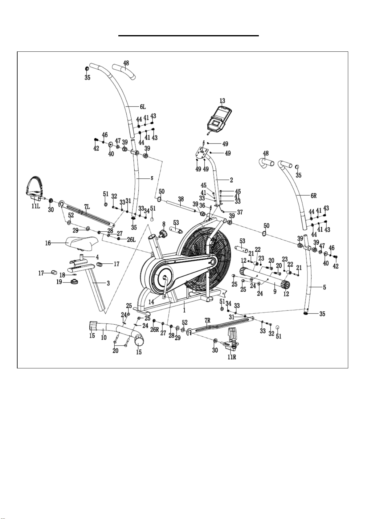
EXPLODED DIAGRAM 1
3
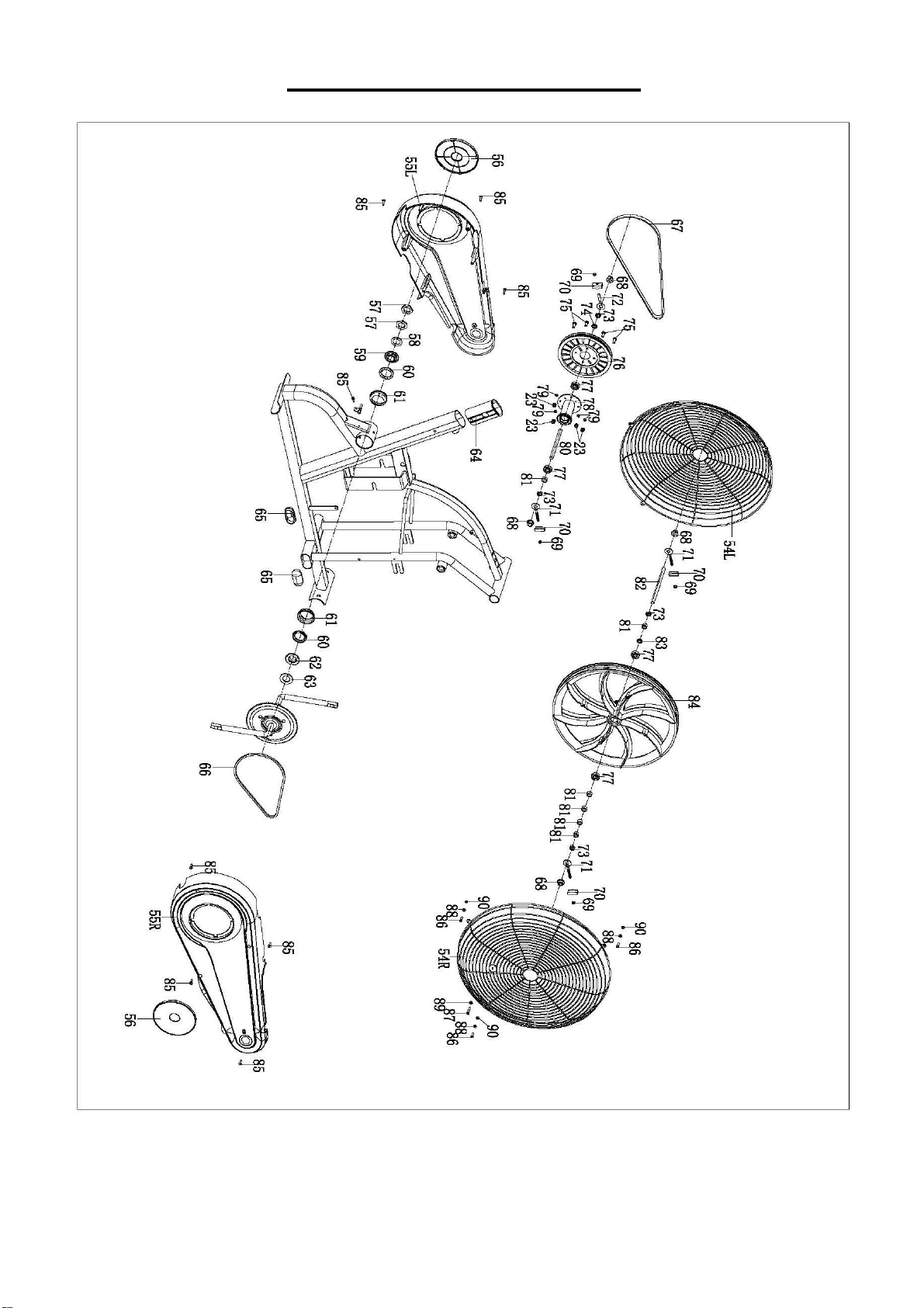
EXPLODED DIAGRAM 2

4
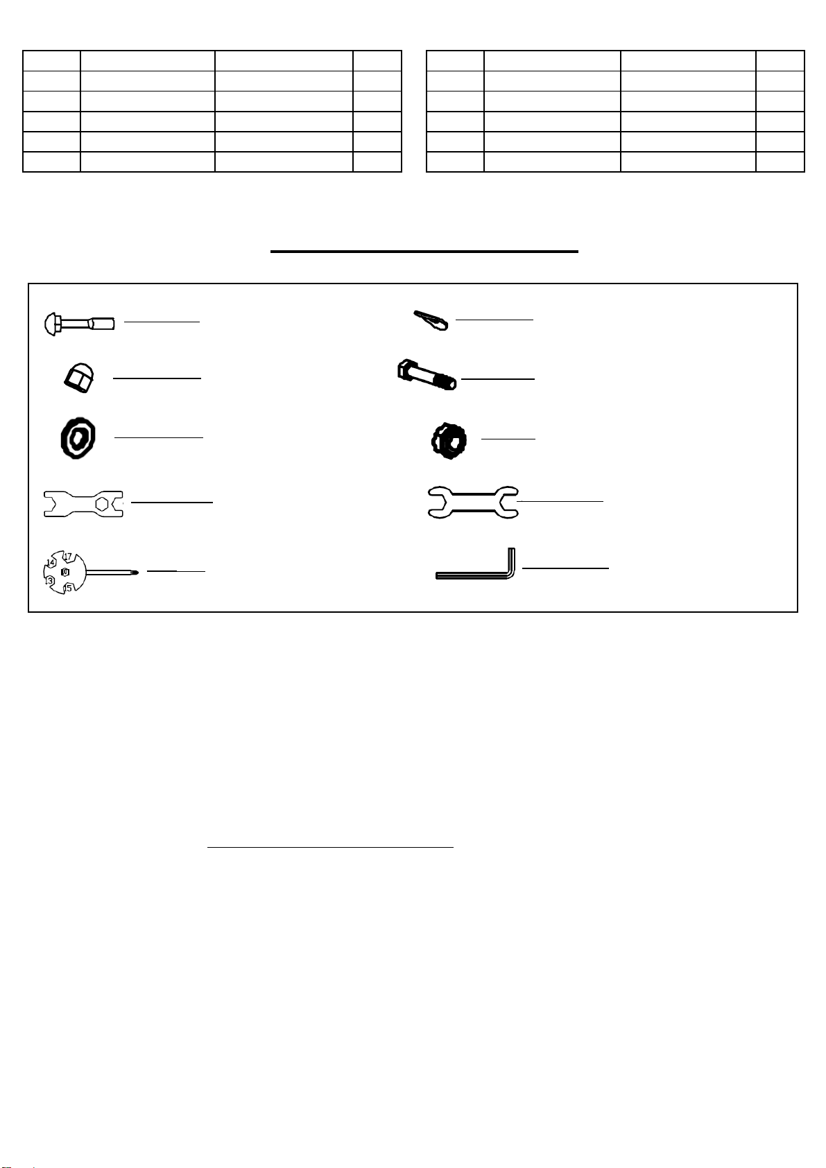
PARTS LIST
No.
Description
Spec.
Qty.
No.
Description
Spec.
Qty.
1
Main Frame
1
43
Hex Socket Pan
Head Screw
M8X15
4
2
Meter Frame Tube
1
44
Arc Washer
D8X1.5XФ20XR25
4
3
Seat Post
1
45
Hex Socket Pan
Head Screw
M8X35
2
4
Seat Slider
1
46
Spring Washer
D10
2
5
Swing Tube
2
47
D Shape Washer
Ф26XФ16X14XB5
2
6L/R
Armrest
1 pr.
48
Foam Grip
2
7L/R
Connecting Boards
1 pr.
49
Cross Head Screw
M5X10
4
8
Spring Knob
1
50
Wave Washer
D17
2
9
Front Stabilizer
1
51
Cap
4
10
Rear Stabilizer
1
52
Sleeve
2
11L/R
Pedal
1 pr.
53
Foot Supporting
Tube
2
12
Front End Cap
2
54L/R
Protective Cage
1 pr.
13
Meter
1
55L/R
Chain Cover
1 pr.
14
Crank
1
56
Crank Cover
2
15
Rear End Cap
2
57
Hex Nut
2
16
Seat
1
58
Washer
1
17
Cap
2
59
Two Slot Nut
1
18
Flat Washer
D8XD28X2
1
60
Ball Rack
2
19
Knob
1
61
Axle Bowl
2
20
Carriage Bolt
M10XL57
4
62
Three Slot Nut
1
21
Hex Bolt
M6XL45
2
63
Flat Washer
1
22
Transportation
Wheel
2
64
Bushing
1
23
Nylon Nut
M6
6
65
Cap
2
24
Arc Washer
Ф10X1.5XФ25XR2
8
4
66
Chain
1
25
Cap Nut
M10
4
67
Belt
1
26L/R
Nylon Nut
B0.5X20
1 pr.
68
Flange Nut
M10X1
4
27
Spring Washer
D12
2
69
Hex Screw
M6
4
28
Alloy Sleeve
2
70
Adjusting Chain U
Mat
4
29
Flat Washer
D17.1XФ32X2.5
2
71
Adjusting Chain
Bolt
3
30
Bearing
2
72
Adjusting Chain
Bolt
1
31
Alloy Sleeve
2
73
Thin Nut
M10X1
4
32
Hex Bolt
M8X50
2
74
Conical Thin Nut
M10X1
1
33
Flat Washer
D8XФ16X1.5
6
75
Hex Bolt
M6X15
4
34
Nylon Nut
M8
2
76
Belt Pulley
1
35
Round Cap
4
77
Bearing
6000
4
36
Sensor Wire
1
78
Axle
1
37
Extension Wire
1
79
Spring Washer
D6
4
38
Long Axle
1
80
Flywheel Axle
1
39
Plastic Sleeve
6
81
Sleeve
6
40
Flat Washer
D10XФ25X2
2
82
Flywheel Axle
1
41
Spring Washer
D8
6
83
Conical Sleeve
1
42
Hex Socket Pan
Head Screw
M10X20
2
84
Fan Wheel
1
5
No.
Description
Spec.
Qty.
No.
Description
Spec.
Qty.
85
Bolt
ST4.2X18
8
90
Nylon Nut
M5
3
86
Cross Head Screw
M5X15
3
91
Wrench
S17,19
1
87
Cross Head Screw
M6X30
1
92
Wrench
S13,14
1
88
Flat Washer
D5XФ10X1.0
3
93
Spanner
S10,13,14,15,17
1
89
Flat Washer
D6XФ12X1.2
1
94
Allen Wrench
S6
2
HARDWARE PACKAGE
Ordering Replacement Parts (U.S. and Canadian Customers only)
Please provide the following information in order for us to accurately identify the part(s) needed:
✓ The model number (found on cover of manual)
✓ The product name (found on cover of manual)
✓ The part number found on the “EXPLODED DIAGRAM” and “PARTS LIST” (found near the
front of the manual)
Please contact us at [email protected] or 1- 877 - 90SUNNY (877-907-8669).
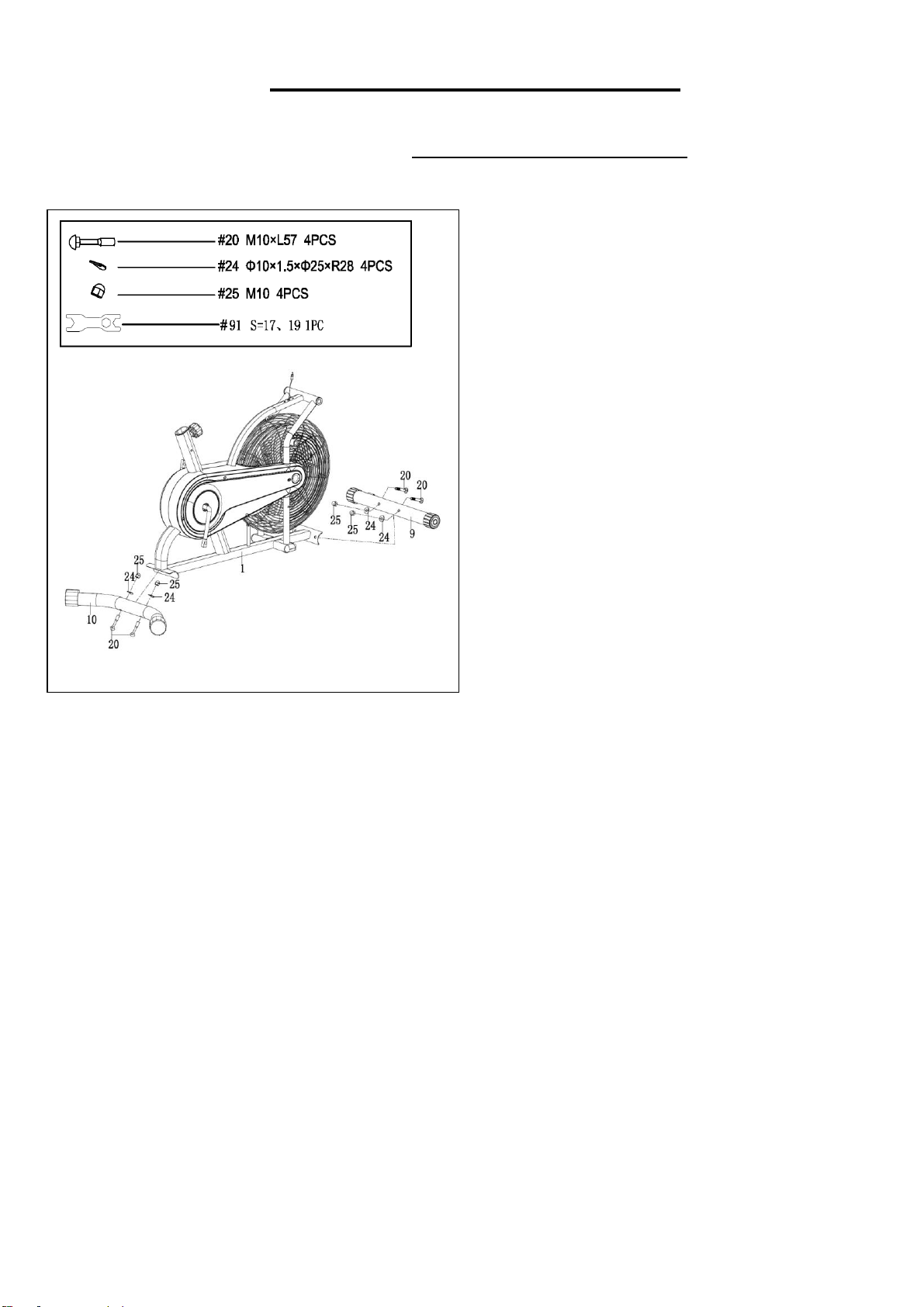
#91 S17,19 1PC
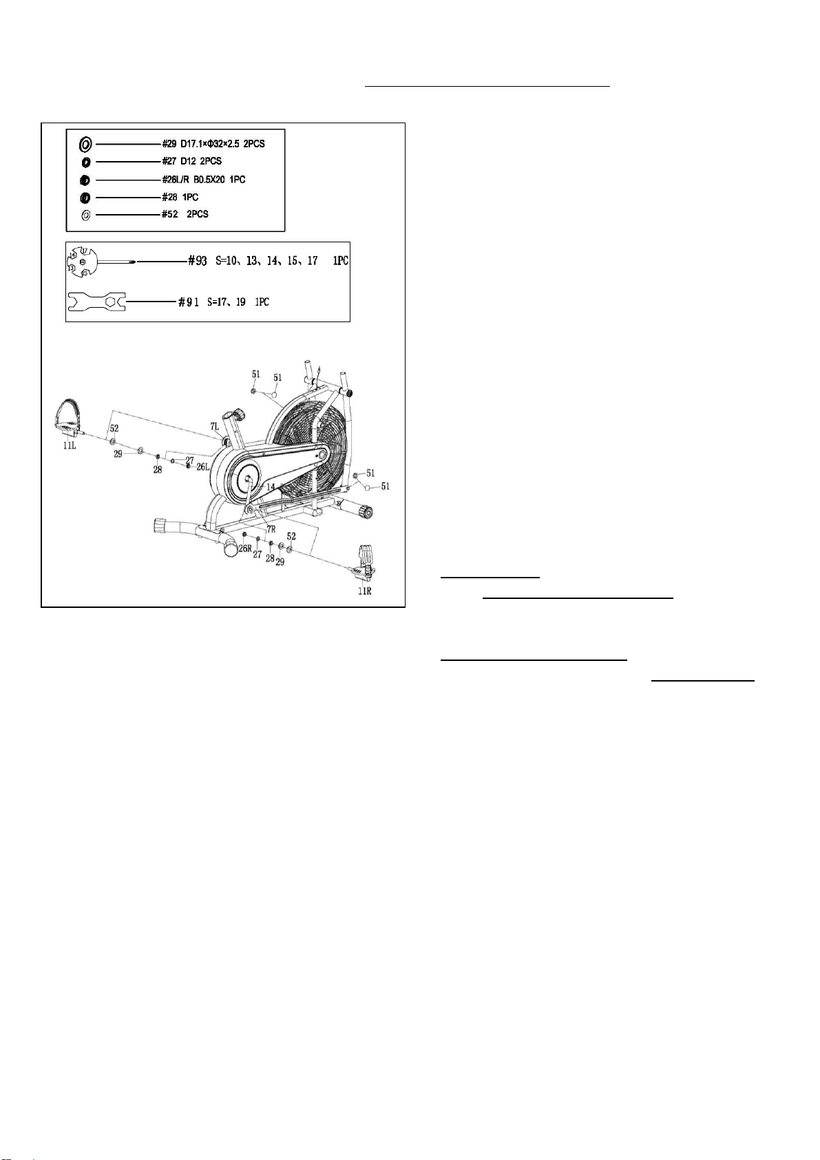
#93 S10,13,14,15,17 1PC
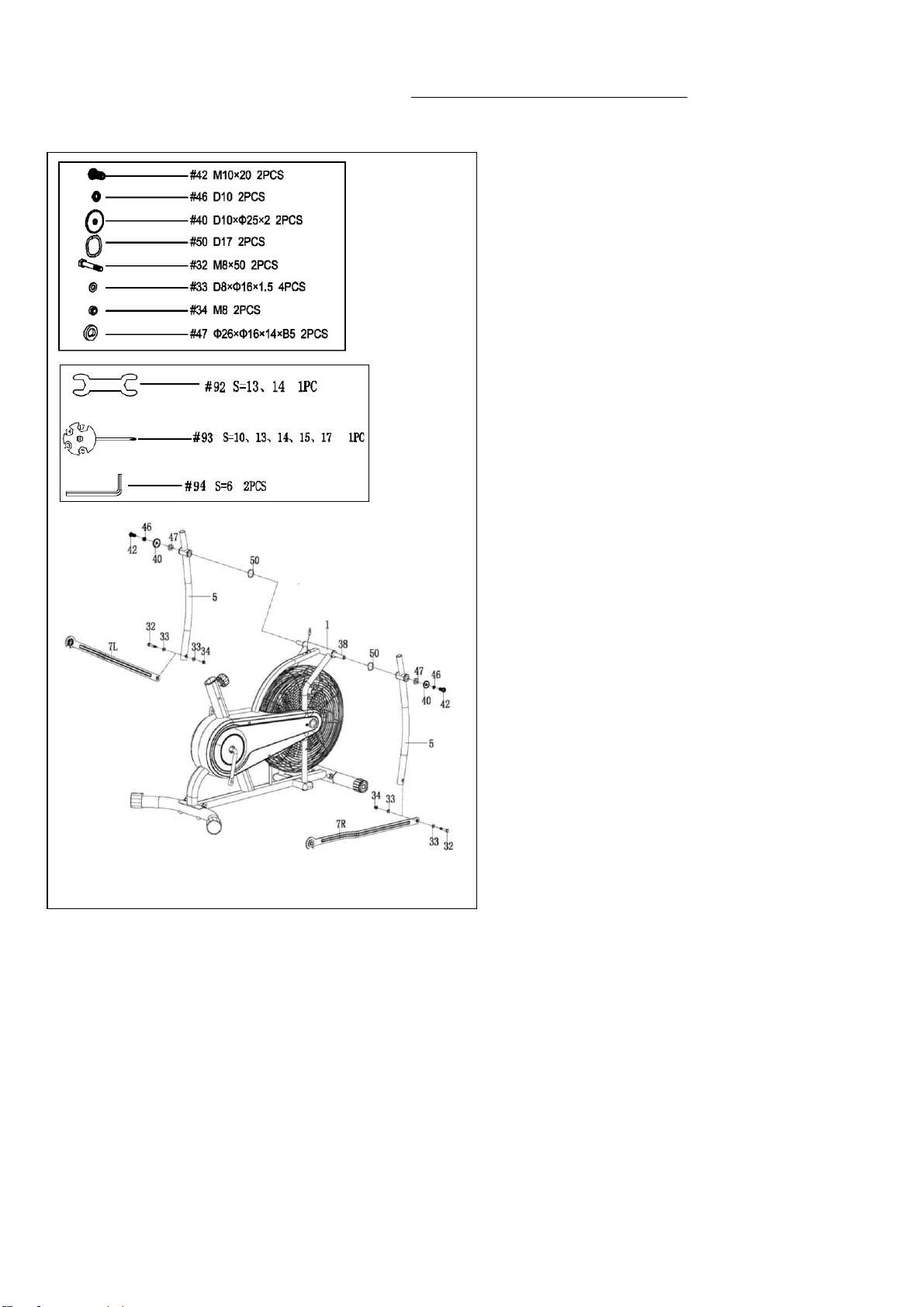
#92 S13,14 1PC
#94 S6 2PCS
#20 M10XL57 4PCS
#24 Ф10X1.5XФ25XR28 4PCS
#25 M10 4PCS
#32 M8X50 2PCS
#33 D8XФ16X1.5 4PCS
#34 M8 2PCS
6
ASSEMBLY INSTRUCTIONS
We value your experience using Sunny Health and Fitness products. For assistance with parts or
(877-907-8669).
STEP 1:
Attach the Front Stabilizer (No. 9) and
Rear Stabilizer (No. 10) to the Main
Frame (No. 1) with 4 Carriage Bolts (No.
20), 4 Arc Washers (No. 24) and 4 Cap
Nuts (No. 25). Tighten and secure with the
Wrench (No. 91).
7
We value your experience using Sunny Health and Fitness products. For assistance with parts or
(877-907-8669).
STEP 2:
Remove 2 Hex Socket Pan Head
Screws (No. 42), 2 Spring Washers
(No. 46), 2 Flat Washers (No. 40), 2 D
Shape Washers (No. 47), and 2 Wave
Washers (No. 50) from the Long Axle
(No. 38) using Allen Wrench (No. 94).
Insert the Long Axle (No. 38) to the Main
Frame (No. 1), then attach the Swing
Tubes (No. 5) to both sides of Main
Frame (No. 1) with 2 Hex Socket Pan
Head Screws (No. 42), 2 Spring
Washers (No. 46), 2 Flat Washers (No.
40), 2 D Shape Washers (No. 47), and 2
Wave Washers (No. 50) that were just
removed. Tighten and secure with the
Allen Wrench (No. 94). Do not fully
tighten the screws at this time.
Attach the Connecting Boards (No.
7L/R) to the Swing Tubes (No. 5) with 2
Hex Bolts (No. 32), 4 Flat Washers (No.
33) and 2 Nylon Nuts (No. 34). Tighten
and secure with the Wrench (No. 92) and
Spanner (No. 93). Do not fully tighten the
bolts at this time.
8
We value your experience using Sunny Health and Fitness products. For assistance with parts or
(877-907-8669).
STEP 3:
Remove 2 Nylon Nuts (No. 26L/R), 2
Spring Washers (No. 27), 2 Alloy
Sleeves (No. 28), 2 Flat Washers (No.
29), 2 Sleeves (No. 52) from the Pedal
(No. 11L/R) using Wrench (No. 91).
Insert the Pedal (No. 11R) into the
Connecting Board (No. 7R), then attach
to the Crank (No. 14) with Spring Washer
(No. 27), Alloy Sleeve (No. 28), Flat
Washer (No. 29), Sleeve (No. 52) that
were just removed using Spanner (No. 93)
to tighten. Then screw the Nylon Nut (No.
26 R) to Pedals (No. 11 R) using Wrench
(No. 91). Repeat the same assembly for
left Pedal (No.11L).
NOTE:Make sure to attach Right Pedal
(No. 11R), marked R, to the Right Crank
(No. 14). It should be tightened
CLOCKWISE. Then screw Nylon Nut (No.
26R) COUNTER-CLOCKWISE. Attach the
Left Pedal (No. 11L), marked L, to the Left
Crank (No. 14). It should be tightened
COUNTER-CLOCKWISE. Then screw
Nylon Nut (No. 26L) CLOCKWISE.
Attaching the Pedals (No. 11L/R) to the
wrong Cranks (No. 14) or turning it the
wrong direction will permanently damage
the crank and the pedal.
Now you can fully tighten the 2 Hex
Socket Pan Head Screws (No. 42) and 2
Hex Bolts (No. 32) from step 2, then cover
with 4 Caps (No. 51).
9
We value your experience using Sunny Health and Fitness products. For assistance with parts or
(877-907-8669).
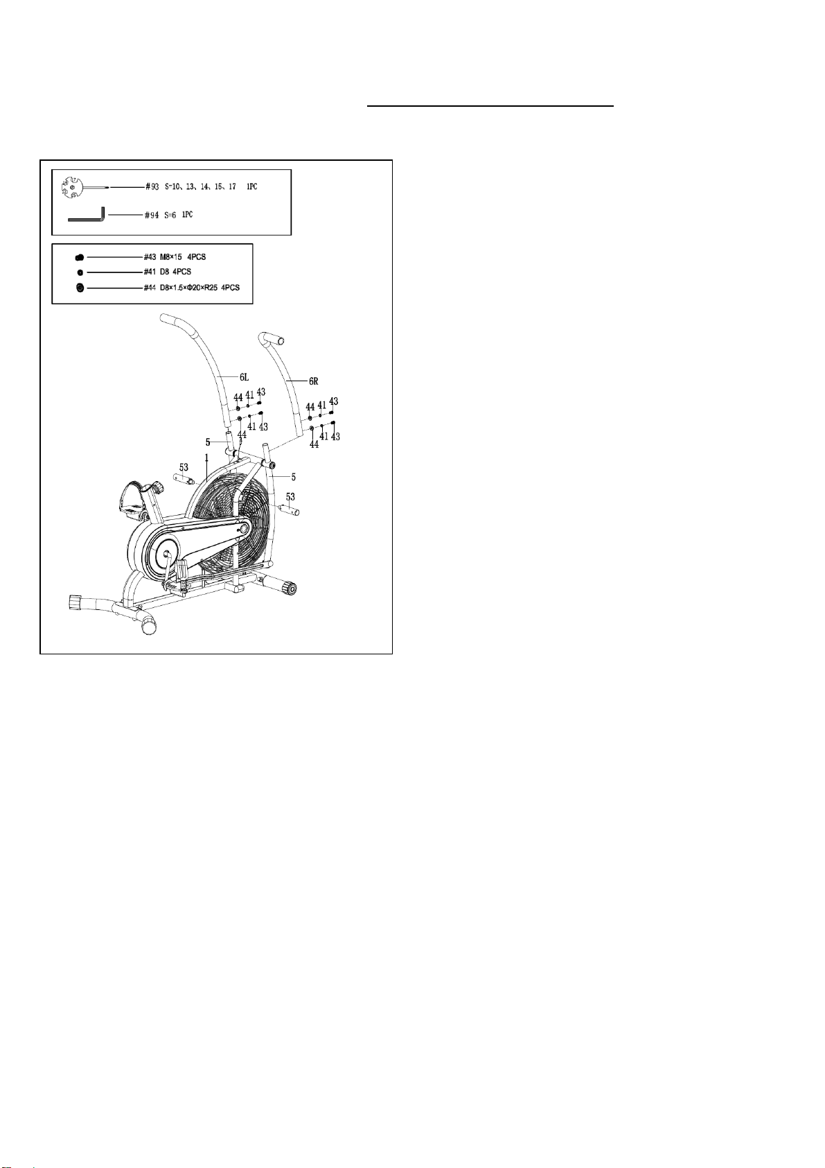
STEP 4:
Remove 4 Hex Socket Pan Head Screws
(No. 43), 4 Spring Washers (No. 41) and 4
Arc Washers (No. 44) from the Swing
Tubes (No. 5) using Allen Wrench (No. 94).
Attach the Armrests (No. 6L/R) to the
Swing Tube (No. 5) with 4 Hex Socket Pan
Head Screws (No. 43), 4 Spring Washers
(No. 41) and 4 Arc Washers (No. 44) that
were just removed. Tighten and secure with
Allen Wrench (No. 94).
Lock 2 Foot Supporting Tubes (No. 53) on
the Main Frame (No. 1) using the Spanner
(No. 93).
10
We value your experience using Sunny Health and Fitness products. For assistance with parts or
(877-907-8669).
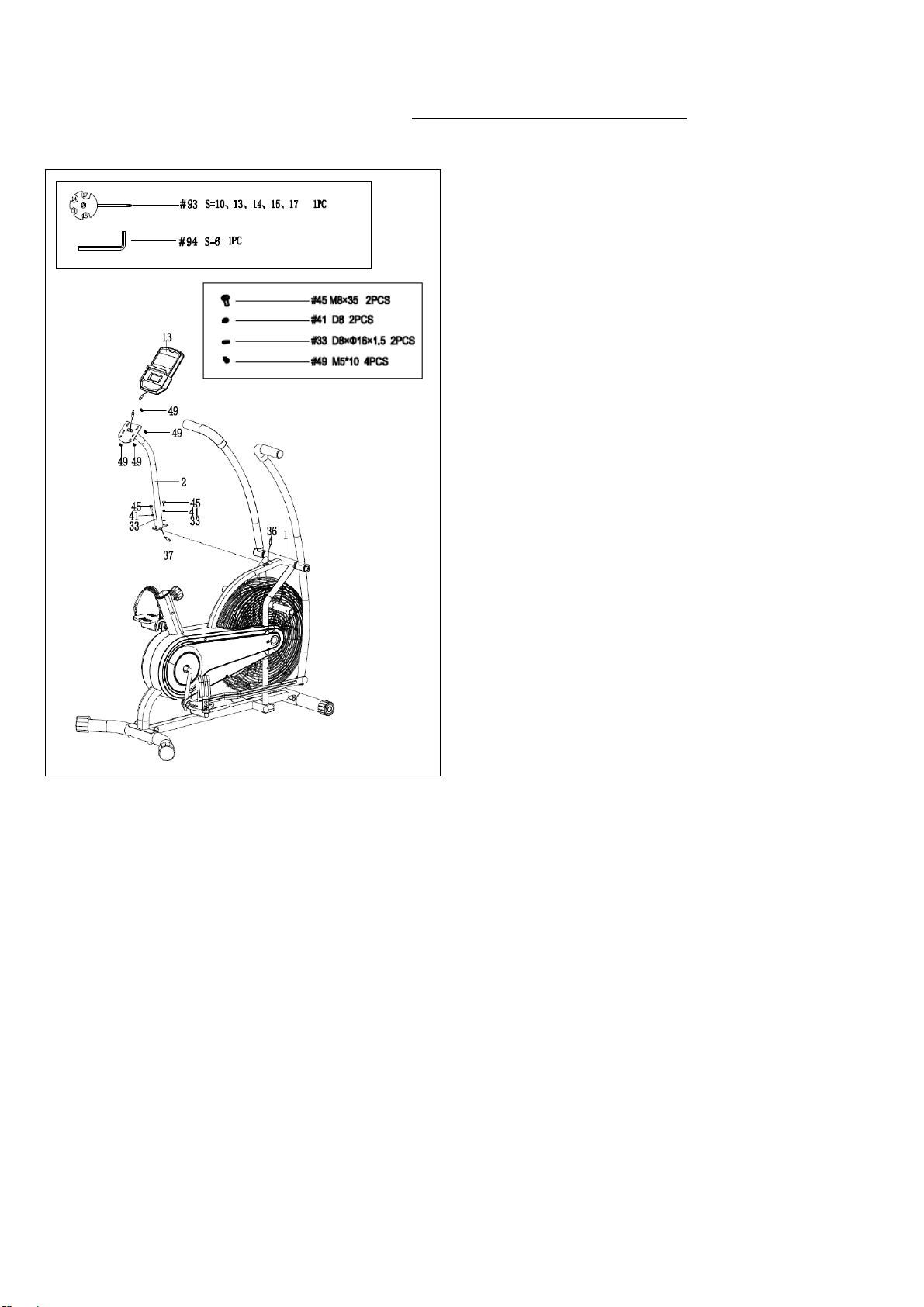
STEP 5:
Remove 2 Hex Socket Pan Head Screws
(No. 45), 2 Spring Washers (No 41) and 2
Flat Washers (No. 33) from the Main
Frame (No. 1) using Allen Wrench (No.
94).
Connect the Sensor Wire (No. 36) and
Extension Wire (No. 37).
Attach the Meter Frame Tube (No. 2) to the
Main Frame (No. 1) with 2 Hex Socket Pan
Head Screws (No. 45), 2 Spring Washers
(No 41) and 2 Flat Washers (No. 33) that
were just removed. Tighten and secure with
Allen Wrench (No. 94).
Connect the Extension Wire (No. 37) with
wire of Meter (No. 13).
Remove 4 Cross Head Screws (No. 49)
from the Meter (No. 13) using Spanner (No.
93).
Attach the Meter (No. 13) to the Meter
Frame Tube (No. 2) with 4 Cross Head
Screws (No. 49) that were just removed.
Tighten and secure with Spanner (No. 93).
NOTE: Make sure you do not cut or pinch
any wires inside the tube.
11
We value your experience using Sunny Health and Fitness products. For assistance with parts or
(877-907-8669).
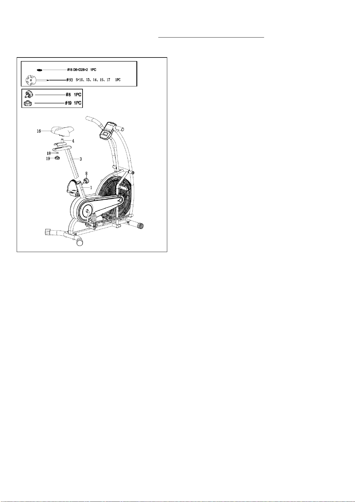
STEP 6:
Remove the Spring Knob (No. 8) from the
Main Frame (No. 1). Insert the Seat Post
(No. 3) to the tube of Main Frame (No. 1),
then secure with Spring Knob (No. 8) after
adjusting to the proper position.
Remove the Flat Washer (No. 18) and Knob
(No. 19) from the Seat Slider (No. 4). Attach
the Seat Slider (No. 4) to the Seat Post (No.
3) with the Flat Washer (No. 18), then
tighten Knob (No. 19).
Attach the Seat (No. 16) to the Seat Slider
(No. 4). Tighten and secure with Spanner
(No. 93).
The assembly now is complete!
12
ADJUSTMENTS GUIDE
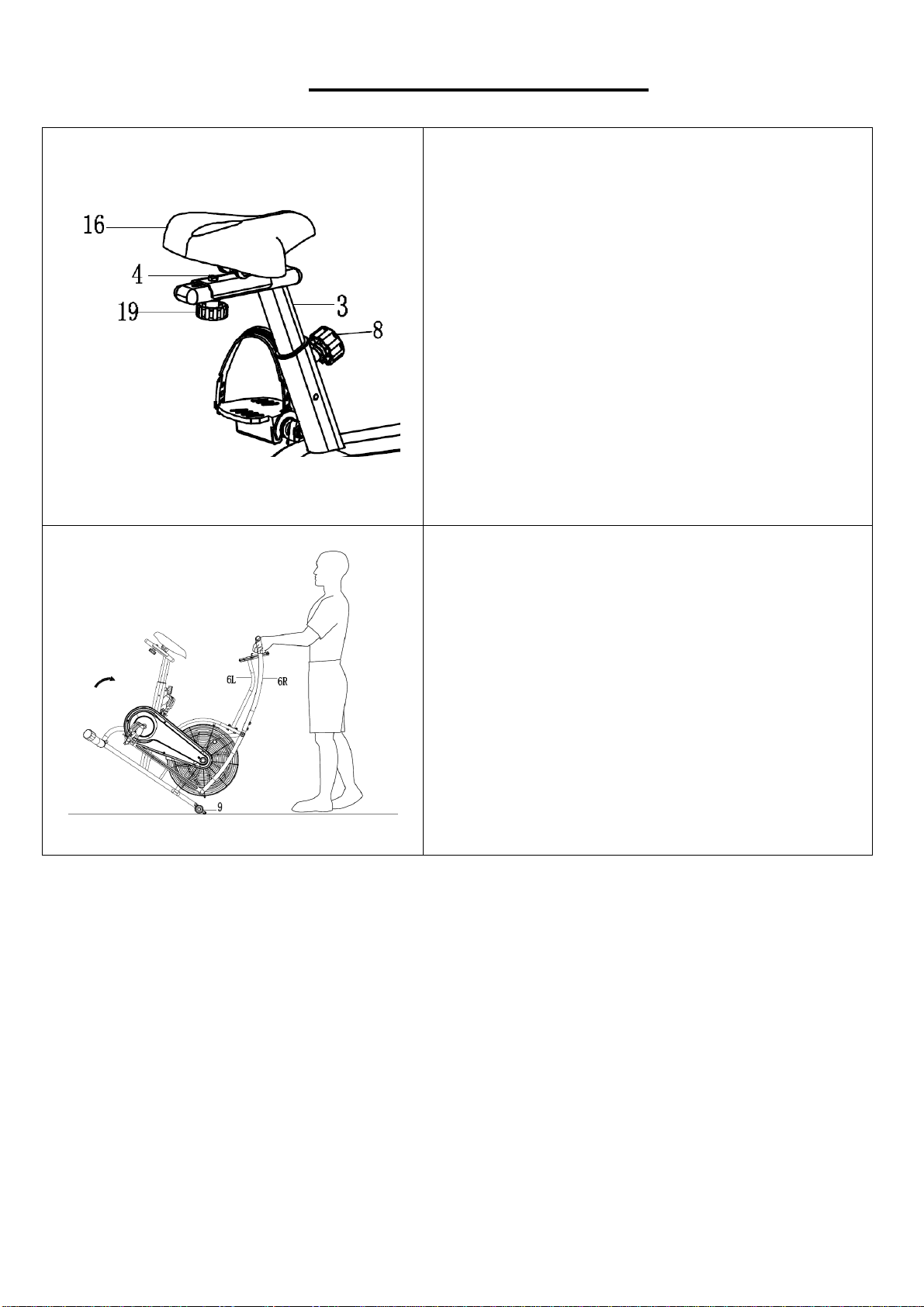
ADJUSTING THE SEAT
The Seat (No. 16) of this bike is fully adjustable
as it moves up, down, forward and backward.
To adjust the height of the Seat Post (No. 3),
loosen and pull the Spring Knob (No. 8)
outward, then raise or lower the Seat (No. 16) to
the desired height. Once adjusted, re-insert and
tighten the Spring Knob (No. 8) to secure the
Seat Post (No. 3) in place.
To adjust the Seat (No. 16) back and forth,
loosen Knob (No. 19), then slide the Seat Slider
(No. 4) to the desired position. Once positioned,
tighten the Knob (No. 19) to secure the Seat
Slider (No. 4) in place.
MOVING THE BIKE
To move the bike, stand at the front of the bike so
that you’re directly in front of the Armrests (No.
6L/R). Firmly grasp and hold each side of the
Armrests (No. 6L/R), place one foot on the
Front Stabilizer (No. 9) and tilt the bike towards
you until the transportation wheels on the Front
Stabilizer (No. 9) touch the ground. With the
wheels on the ground, you can transport the bike
to the desired location with ease.
13
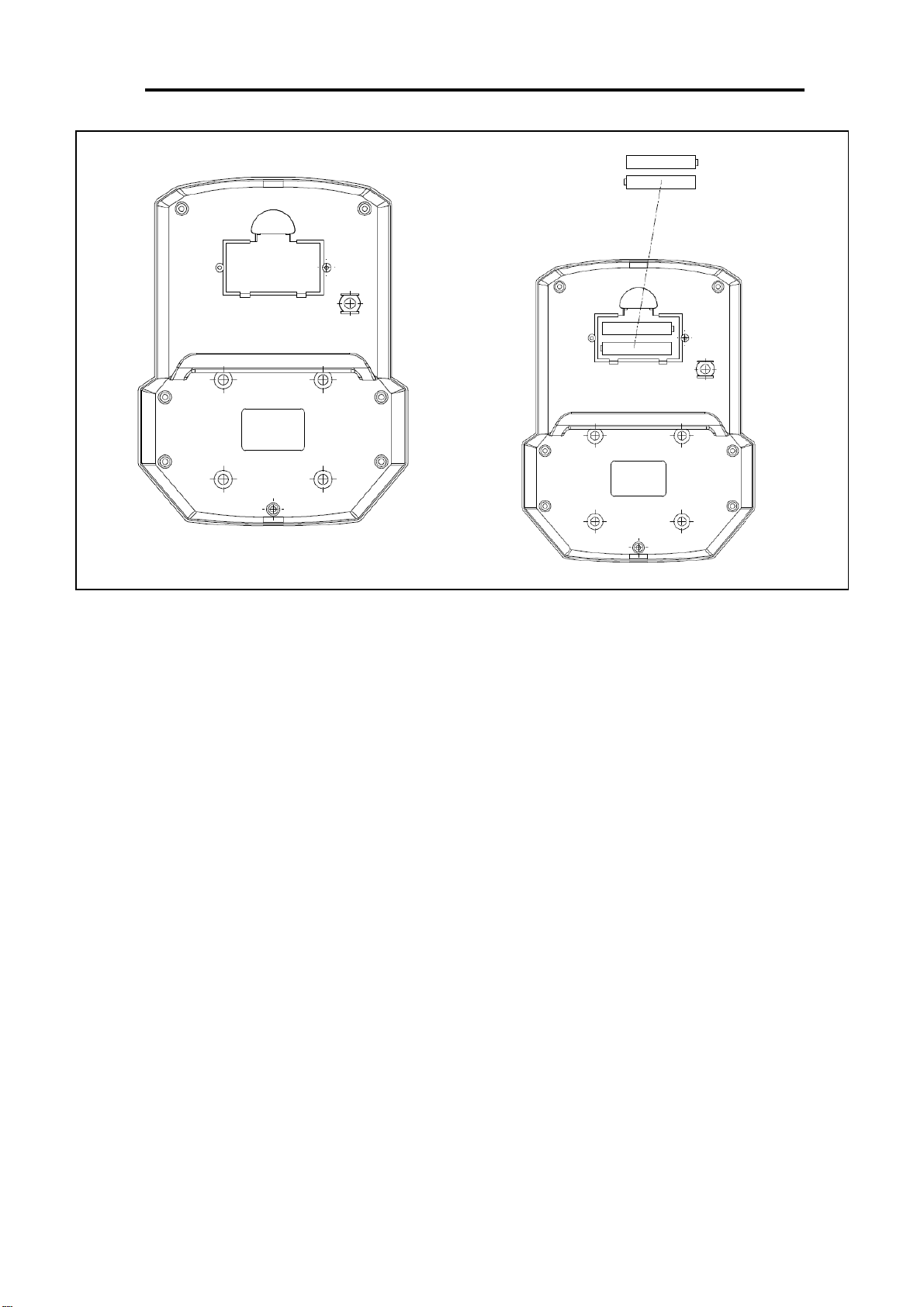
BATTERY INSTALLATION & REPLACEMENT
BATTERY INSTALLATION
The meter uses 2 AAA 1.5V batteries. Open the battery cover from the back of meter, then
put 2 batteries into the battery compartment. Make sure the (+) and (-) ends of the batteries
are in the correct position. Put the battery cover back.
BATTERY REPLACEMENT
Open the battery cover, remove the old batteries, and replace with new batteries. Make
sure the (+) and (-) ends of the batteries are in the correct position. Put the battery cover
back. When changing batteries, always replace both with new batteries. Do not mix old and
new batteries.
14
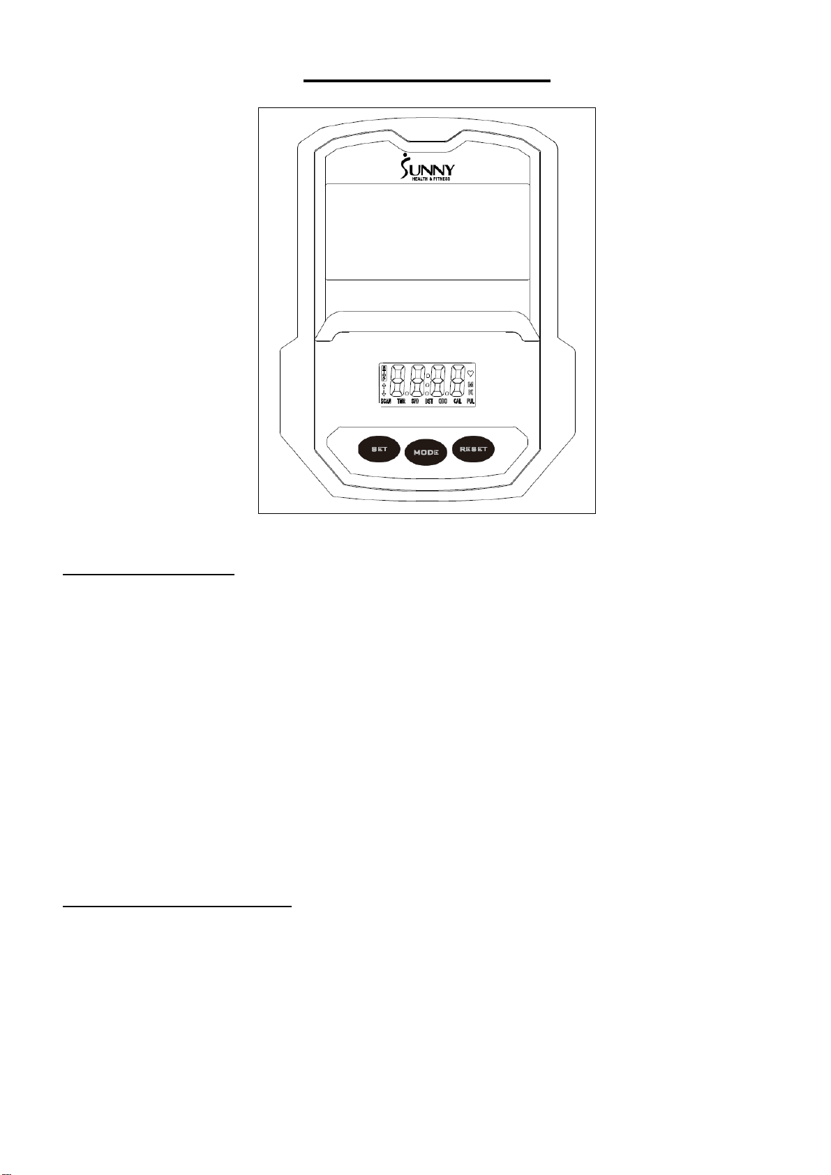
EXERCISE METER
FUNCTION BUTTONS
MODE:
1. Press the button to select TIME, DISTANCE and CAL to preset.
2. Press the button to select any function display values on meter or enter any values to preset.
3. Press and hold the button for 2 seconds to reset all the values to 0 except the Odometer. (When
the user replaces batteries, all the values will reset to ZERO automatically.)
SET:
To set up the target value of TIME, DISTANCE and CAL. Press and hold the button for 2 seconds
to speed up the increment.
RESET:
1. Press and hold the button for 2 seconds to reset the function values except the Odometer,
which can only be reset after replacing the batteries.
2. Press the button when setting the wrong target values for time, distance or calories, the values
will be reset.
FUNCTIONS & OPERATIONS
1. AUTO ON/OFF:
Once the user begins to do exercise, the meter will show the workout value automatically. After
about 4 minutes of inactivity, the meter will turn off. Odometer value does not reset to 0 when the
meter turns off. When user starts exercise again, workout value of odometer will accumulate
continuously.
2. AUTO SCAN:
After the meter is powered on or press Mode key, the meter will display all functions from
TIME-SPEED-DISTANCE-CALORIES-ODOMETER. Each value will be held for 4 seconds.

15
3. SPEED:
Display the current training speed from 0.00 to 99.9 KPH or MPH.
4. DISTANCE:
Accumulates total distance from 0.00 up to 9999. The user may preset target distance by pressing
SET & MODE button. Each increment is 0.1 KM or M. Automatically countdown from targeting
value during exercise.
5. TIME:
Accumulates total time from 00:00 up to 99:59. The user may preset target time by pressing SET
& MODE button. Each increment is 1 minute. Automatically countdown from targeting value during
exercise.
6. CALORIES:
Accumulates calories consumption during training from 0.0 to 9999. The user may also preset the
target calorie before training by pressing SET & MODE button. Each setting increases is 1 cal.
Note: This data is a rough guide which cannot be used in medical treatment.
7. ODOMETER:
Display the total accumulated distance from 0.0 to 9999. User also can press mode key to display
the Odometer value.
8. RESET:
Press and hold the button for 2 seconds to reset all the values except Odometer to be zero.
BATTERY DISPOSAL: The meter uses 2 AAA 1.5V batteries, which are packed with meter. If
there is a problem with the display, try changing the batteries first. Dispose the batteries according
to the laws and regulations of your local region. Some batteries may be recycled.
SPECIFICATIONS:
FUNCTION
AUTO SCAN
Every 4 seconds
TIME
00:00 ~ 99:59
CURRENT
SPEED
The maximum signal can be pickup is
99.9 MPH
TRIP
DISTANCE
0.00 ~ 99.99 MI or 0.00 ~ 9999 MI
CALORIES
0.1 ~ 999.9 KCAL
ODO
0.1 ~ 999.9 MI or 1 ~ 9999 MI
BATTERY TYPE
2pcs of SIZE AAA or UM-4
OPERATING TEMPERATURE
0°C ~ +40°C
STORAGE TEMPERATURE
-10°C ~ +60°C
Version 1.4

16

17

18