Loading ...
Loading ...
Loading ...
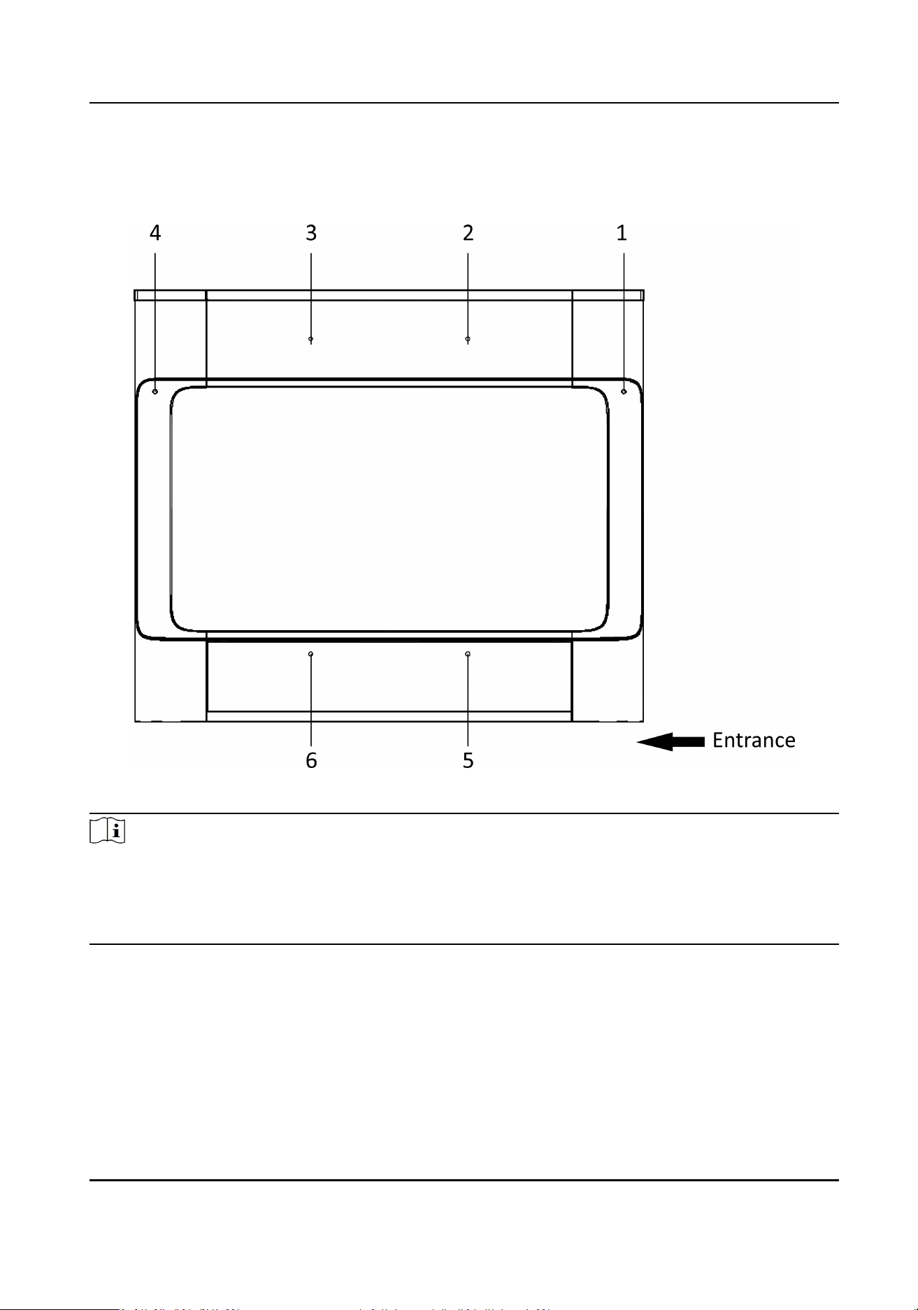
The picture displayed below describes the IR sending/receiving module and their corresponding
posion on the pedestal.
Figure 4-2 IR Module Layout
Note
If the turnsle contains two lanes, standing at the entrance posion, the IR boards on the le
pedestal are the IR sending boards. The IR boards on the right pedestal are the IR receiving boards.
The IR boards on the le side of the middle pedestal are the IR receiving boards, while the IR
boards on the right side of the middle pedestal are the IR sending boards.
4.2 Wiring Electric Supply
Wire electric supply with the switch in the pedestal. Terminal L and terminal N are on the switch,
while terminal PE should connect to a ground wire (yellow and green wire).
Before wiring, open the
protecve cover outside the switch.
DS-K3B411B(L)X Series Swing Barrier User Manual
10
Loading ...
Loading ...
Loading ...