Loading ...
Loading ...
Loading ...
Appendix A. DIP Switch
A.1 DIP Switch Descripon
The DIP switch is on the access control board. No.1 and No 2 is from the low bit to the high bit.
Figure A-1 DIP Switch
When the switch is towards ON, it means the switch is enabled, otherwise, the switch is o.
A.2 DIP Switch Corresponded
Funcons
Note
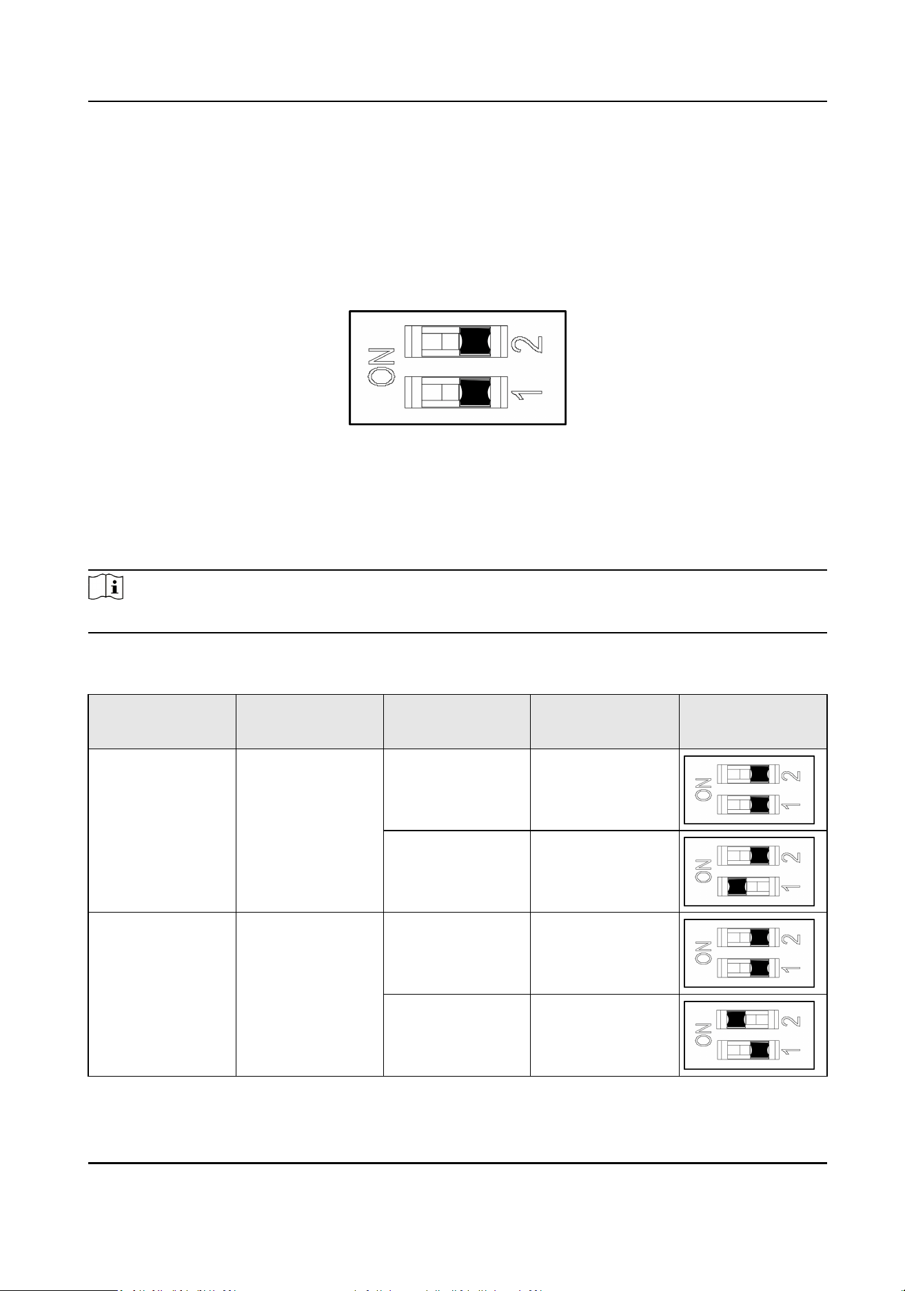
Aer seng the DIP switch, you should reboot the device, or the funcon cannot take eect.
The 2-bit DIP switch corresponded funcons on the access control board are as follows:
Bit
Device Mode Funcon Decimal Value DIP Switch
Address Diagram
1 Work Mode Normal Mode 0
Study Mode 1
2 Keyfob Paring
Mode
Disable Keyfob
Paring Mode
0
Enable Keyfob
Paring Mode
1
DS-K3B411B(L)X Series Swing Barrier User Manual
93
Loading ...
Loading ...
Loading ...