Loading ...
Loading ...
Loading ...
Chapter 2 System Wiring
The preparaon before installaon and general wiring.
Steps
1.
Draw a central line on the
installaon surface of the le or right pedestal.
2.
Draw other parallel lines for installing the other pedestals.
Note
The distance between the nearest two line is L + 200 mm. L represents the lane width.
3.
Slot on the installaon surface and dig installaon holes. Put 4 expansion bolts of M12*120 for
each pedestal.
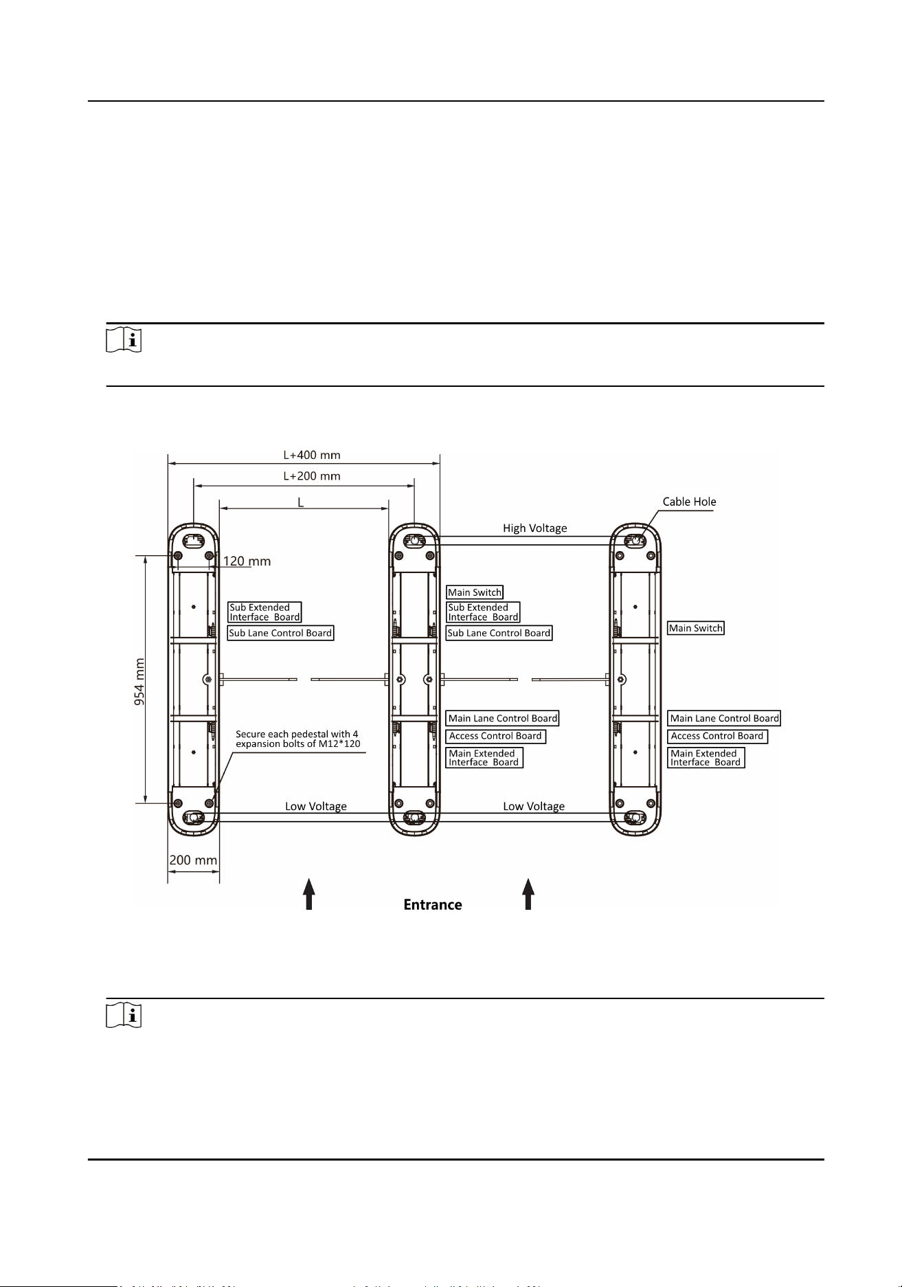
Figure 2-1 Hole Posion and System Wiring
4.
Bury cables. Each lane buries 1 high voltage cable and 1 low voltage cable. For details, see the
system wiring diagram of step 3.
Note
●
High voltage: AC power input
DS-K3B411B(L)X Series Swing Barrier User Manual
3
Loading ...
Loading ...
Loading ...