Loading ...
Loading ...
Loading ...
SIGLENT
SDS2000X User Manual 113
Note:
Signals with DC components or deviation would cause an error or deviation of the
FFT waveform components. To reduce the DC components, set the Channel
Coupling to AC.
To reduce the random noise and aliasing frequency components of repetitive or
single pulse, set the Acquisition of the oscilloscope to Average.
Note: Please refer to the cursors chapter to learn more on cursor operation.
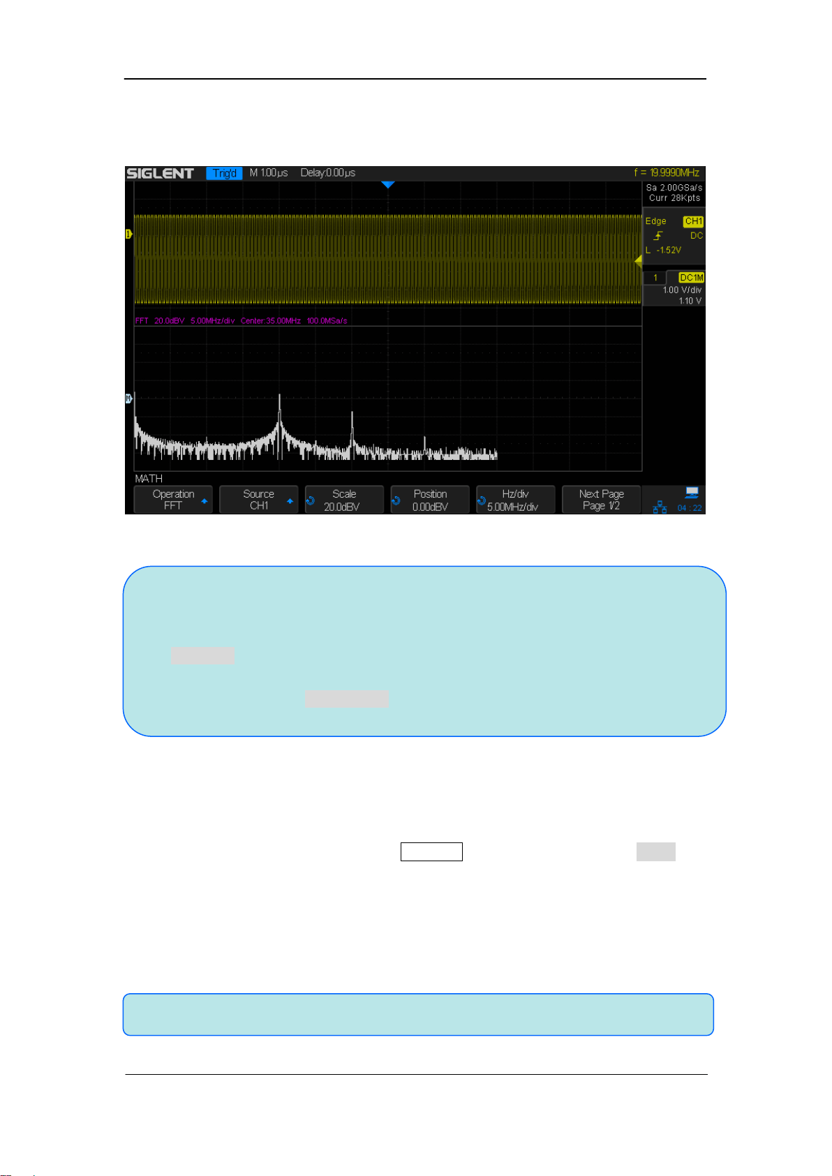
Full Screen: the source channel and the FFT operation results are displayed in
the same window to view the frequency spectrum more clearly and to perform
more precise measurements.
Figure 64: FFT Waveform In Split Mode
To measure FFT waveform:
To make cursor measurements, press the Cursors button, and then press the Mode
softkey to select On to turn the cursors, Use the X1 and X2 cursors to measure frequency
values and the difference between two frequency values (ΔX). Use the Y1 and Y2 cursors
to measure amplitude in dB and difference in amplitude (ΔY).
You can find the frequency value at the first occurrence of the waveform maximum by
using the X at Max Y measurement.
Loading ...
Loading ...
Loading ...