Loading ...
Loading ...
Loading ...
SIGLENT
86 SDS2000X User Manual
In the MISO menu:
a. Press the MISO softkey; then, turn the Universal Knob to select the channel that
is connected to a second SPI serial data line. (If the channel you selected is off,
switch it on.)
b. Press the Threshold softkey; then, turn the Universal Knob to select the MISO
signal threshold voltage level. The threshold voltage level is used in decoding, and
it will become the trigger level when the trigger type is set to the selected serial
decode slot
8. Press the UP softkey to return to the SPI SINGAL menu.
9. Press the MOSI softkey to enter the MOSI menu.
Figure 42: MOSI Menu
In the MOSI menu:
a. Press theMOSI softkey; then, turn the Universal Knob to select the channel that
is connected to a SPI serial data line. (If the channel you selected is off, switch it
on.)
b. Press the Threshold softkey; then, turn the Universal Knob to select the MOSI
signal threshold voltage level. The threshold voltage level is used in decoding, and
it will become the trigger level when the trigger type is set to the selected serial
decode slot.
10. Press the UP softkey to return to the SPI SINGAL menu.
11. Press the CS softkey to open the SPI CS menu.
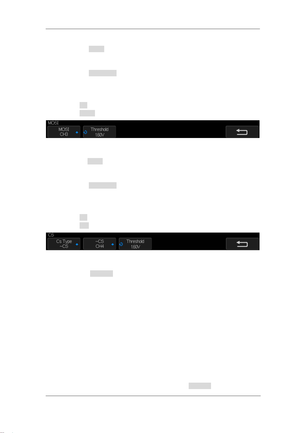
Figure 43: SPI CS Menu
In the SPI CS menu:
a. Press the CS Type softkey to select a framing signal that the oscilloscope will use
for determining which clock edge is the first clock edge in the serial stream. You
can set the oscilloscope to trigger during a high chip select (CS), a low chip select
(~CS), or after a Timeout period during which the clock signal has been idle.
If the framing signal is set to CS (or ~CS), the first clock edge as defined,
rising or falling, seen after the CS (or ~CS) signal transitions from low to high
(or high to low) is the first clock in the serial stream.
Press the CS or ~CS softkey; then, turn the Universal Knob to select the
channel that is connected to the SPI frame line. The label (~CS or CS) for the
source channel is automatically set. The data pattern and the clock transition
must occur during the time when the framing signal is valid. The framing
signal must be valid for the entire data pattern.
If the framing signal is set to Timeout, the oscilloscope generates its own
internal framing signal after it sees inactivity on the serial clock line.
CLK Timeout — Select Clock Timeout in the Cs Type softkey, then select
Loading ...
Loading ...
Loading ...