Loading ...
Loading ...
Loading ...
SIGLENT
SDS2000X User Manual 85
SPI Triggering and Serial Decode
Please note the order of ―Setup for SPISignals‖, ―SPITriggering‖and ―SPIDecode‖ to
trigger and decode the signals.
Setup for SPI Signals
Serial Peripheral Interface (SPI) signals setup consists of connecting the oscilloscope to a
clock, MOSI data, MISO data, and framing signal, then setting the threshold voltage level
for each input channel, and finally specifying any other signal parameters.
To set up the oscilloscope to capture SPI signals, use the Signal softkey which appears in
the Decode function menu:
1. Press the Decode button on the front panel to enter the Decode function menu.
2. Press the Serial softkey and select the desired slot (Serial 1 or Serial 2).
3. Press Decode softkey and select SPI with the Universal Knob, and then press the
knob to confirm. Serial 1 and Serial 2 could not be set to SPI at the same time. And
the default setup of Serial 2 is SPI.
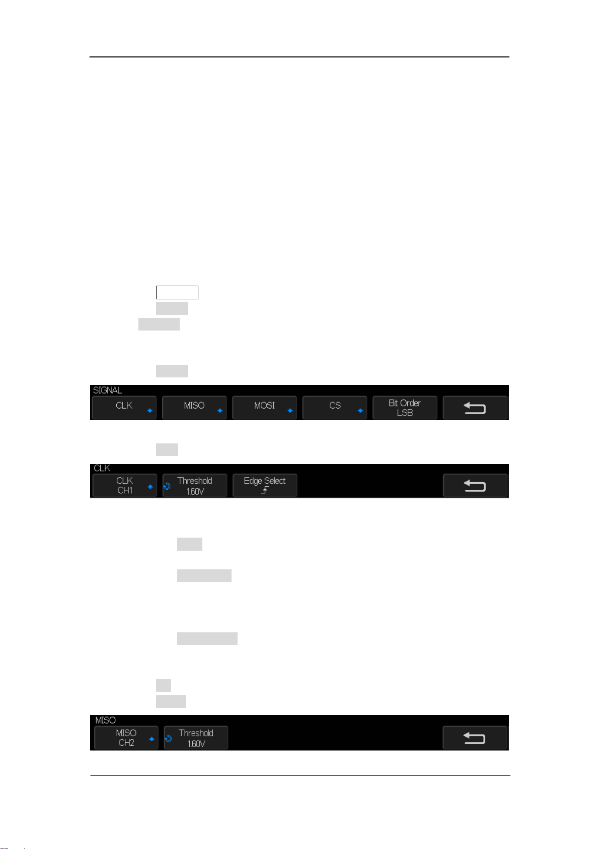
4. Press the Signal softkey to enter the SPI SIGNAL menu.
Figure 39: SPI SINGAL Menu
5. Press the CLKsoftkeyto enter SPI CLK menu.
Figure 40: SPI Clock Menu
In the SPI Clock Menu:
a. Press the CLK softkey; then, turn the Universal Knob to select the channel
connected to the SPI serial clock line.
b. Press the Threshold softkey; then, turn the Universal Knob to select the clock
signal threshold voltage level. The threshold voltage level is used in decoding,
and it will become the trigger level when the trigger type is set to the selected
serial decode slot.
c. Press the Edge Select softkey to select rising edge or falling edge for the
selected clock source. This determines which clock edge the oscilloscope will use
to latch the serial data.
6. Press the UP softkey to return to the SPI SINGAL menu.
7. Press the MISO softkey to enter the MISO menu.
Figure 41: MOSI Menu
Loading ...
Loading ...
Loading ...