Loading ...
Loading ...
Loading ...
-,
.
PUMP
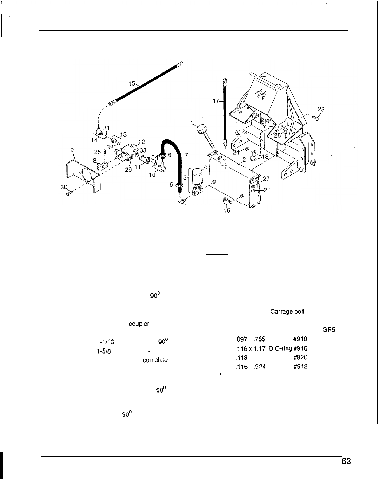
&TANK ASSEMBLY
PUMP &TANK ASSEMBLY
5
Ref
No.
No.
Used
1 1
2
1
3 1
4
1
5
1
6
2
7
1
8
1
9
1
10
1
11 1
12 1
13 1
14 1
15
1
16 1
17
1
18 1
Description
Tank breather cap with dipstick
Tank assembly
Filter
&
housing assy. complete
Filter element
3/4 Hose
x
3/4 pipe 90' elbow
1/2 Screw hose clamp
3/4
x
40 Low pressure suction hose
Pump drive
coupler
Pump mounting bracket
1
-1/16
-
12
x
3/4 Hose 90' elbow
1238
-
12
x
1
-
1/16
-
12 Reducer
Pump assembly
complete (see page
62 for breakdown)
1
-
5/16
-
12
x
7/8
-
14 Reducer with
O
-
ring
7/18
-
14
x
9/16 Flare 90' elbow
9/16 Flare
x
9/16 flare
x
34 high
pressure hose assembly
1/2
x
1/2 90' Pipe elbow
9/16
Flare
x
1/2
NPT
x
28
high
pressure hose assembly
Hose clamp
HARDWARE
Ref
No.
Description
'23
1/4 NC
x
3/4 Hex head cap screw
GR5
24
1/4 NC Flanged locknut
'25
5/16 NC
x
1
Cup point square head set
'26
3/8 NC Hex nut, plated
'27
3/8 Standard lockwasher
'28
3/8
NC
x
3/4 Carrage
bott
'29 1/2 NC Hex locknut
'30
1/2 NC
x
1
Hex head cap screw GR5
32
.116x 1.17IDO-ring#916
33 .118
x
1.48
ID
O-ring ##920
34
.116
x
.924
ID
O
-
ring #912
screw GD5
31
.097
x
.755 ID O
-
ring #910
Obtain Locally
Loading ...
Loading ...
Loading ...