Loading ...
Loading ...
Loading ...
ASSEMBLY
INSTRUCTIONS
'5
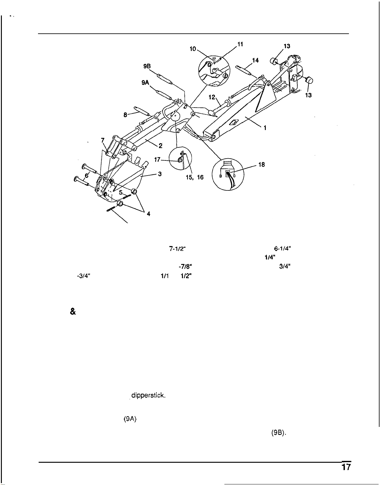
1.
Boom
7.
Bucket arm
13.
Bumper pad
2.
Dipperstick
8.
1
x
7-1/2"
Pivot
pin
14.
1
x
6-1"'
Pivot
pin
3.
Bucket
9.
1
x
4
-
7/8
Pivot
pin
15. 1/4"
Flange locknut
4.
Retaining
sleeve
10. 1/4
x
1
-7/8"
Clevis
pin
16. 1/4
x
3/4"
Bolt
5.
5/16
x
1
-3/4"
Spiral pin
11. 1/1
6
x
1/2"
Cotter
pin
17.
Hose
clamp
6.
Rotating pivot pin
12.
Dipperstick cylinder
18.
Hydraulic
hose
routing
Figure
6.
Dipperstick
&
Bucket Assembly
4.
Bucket
&
Dipperstick
Installation
(Figure
6)
1. Remove shipping bar and attaching hardware
(Figure
4,
reference
1).
2.
Align dipperstick
(2)
with boom (1). Join them
with pivot pin
(8).
Line up the pivot pin hole with
hole in pivot bushing and secure with clevis pin
(1
0)
and cotter pin (1 1).
3.
Disconnect bucket hydraulic cylinder base end
where it attaches to the
,dipperstick. Route
bucket cylinder hoses through dipperstick
openings (1
8).
Make sure hoses are not
twisted. Install pivot pin
(9A) and secure with
clevis
pin
(1
0)
and cotter pin
(1 1).
5.
Fasten the bucket rod end hose (orange mark)
with the clamp (17) on the right side of the
dipperstick as shown. Leave 16
"
of hose
toward the rod end fitting past the clamp. Snug
bolt
(16) and locknut (15) but do not torque
down. Fasten bucket base end hose (white
mark) with clamp on left side
of
the dipperstick,
leaving 16
"
of hose extending toward the base
end fitting past the clamp. Snug bolt (16) and
locknut (15) but do not torque down. When
backhoe is installed on tractor, operate
dipperstick through the entire range of
movement and check that hose length beyond
the clamp is sufficient. After completing check,
tighten both hose clamps.
Align dipperstick cylinder
(12)
with dipperstick
and install pivot pin
(9B). Line up pivot pin hole
with hole in pivot bushing. Secure with clevis
pin (10) and cotter pin (1 1).
Loading ...
Loading ...
Loading ...