Loading ...
Loading ...
Loading ...
Attaching Backhoe
To
Tractor
The backhoe hydraulicsystem will be used
to
make
mounting on tractor easier.
It
is necessary this be
done with tractor engine running at
idle.
Am
The operator or service
person must be competent and use extreme
care during
this operation
to
prevent
equipment damage and personal Injury.
Always stand on the tractor side or
reannrard
of
backhoe to avoid the posslbliity
of
being
trapped should
the
boom swing control be
accidentally activated.
1.
Be sure backhoe controls are in centered and
neutral position.
2.
With the backhoe hydraulic pump securely
mounted, and tractor PTO and transmission in
neutral, start tractor engine idling. Engage PTO
verycarefully and allow pump to start smoothly.
Refer to the
H6522 Owner’s Manual for rear
PTO engagement.
Very little engine power 1s
requ re
o
power hydraulic system In this
mode. Should engine pull down excessively,
check plumbing hook
-
up for reversed lines or
a control lever stuck
in
an operating position.
3.
Raise
backhoe
with
stabilizer controls to
align
grooves in the right and left set plates (1) with
the cross shaft
(2)
of the sub
-
frame assembly.
Level backhoe from side to side with stabilizer
controls. See Figure
13.
4. Use the right control lever and position the
backhoe
so
that the sub
-
frame
is
lowest at the
crossmember end.
5.
Position the backhoe
so
that the sub
-
frame,
cross shaft locks completely into the grooves
of the right and left plate assemblies.
.
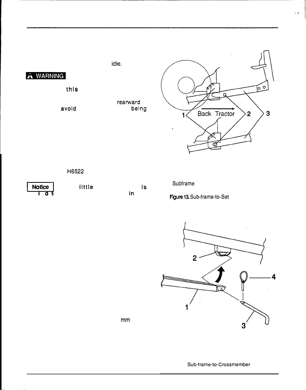
6.
Use the right control lever to bring the
crossmember end of the sub
-
frame into the
crossmember. Lock the sub
-
frame (1) into the
crossmember
(2)
with
the
19
x
397
mm
pin (3)
and Klik pin (4). See figure 14.
7.
Turn the upper link
(1)
threaded end until the
hole aligns with the center hole of the top link
bracket
(2).
Install the top link pin
(3)
and the
Klik pin (4). See Figure
15.
24
ASSEMBLY INSTRUCTIONS
1.
Set
plate
2.
Subframe cross shaft
3.
Bachoe sub
-
frame
Fyute13.
Sub-frame-to-Set Plate Installation
1.
Sub
-
frame end
3.
Pin
2.
Crossrnernber
assembly
4.
Klik
pin
Figure
14.
Sub-frame-to-Crossrnember
Installation
Loading ...
Loading ...
Loading ...