Loading ...
Loading ...
Loading ...
-
SERVICE
&
MAINTENANCE INSTRUCTIONS
4.
Clean all components in solvent and blow dry
with low pressure air.
ASSEMBLY
1.
Lubricate O
-
rings and seals with clean
hydraulic fluid.
2.
Assemble using exploded view. Note that items
(48)
and
(4H)
are used with lockwire cylinder
only. Note that items
(4J)
and
(9)
are used with
threaded plug cylinder only.
3.. Torque locknut to
175
ft
-
lbs.
4.
Carefully insert piston and rod into barrel.
It
will
be necessary to compress wear ring and piston
seal to avoid damage during insertion.
Lock Wire Installation
Rotate gland until lock wire starting hole in gland is
visible through slot in barrel. Insert lock wire hook
into hole and pull into groove by rotating gland until
wire is completely seated.
Threaded Plug Installation
Screw threaded plug into cylinder using a spanner
wrench, or carefully use a punch and hammer.
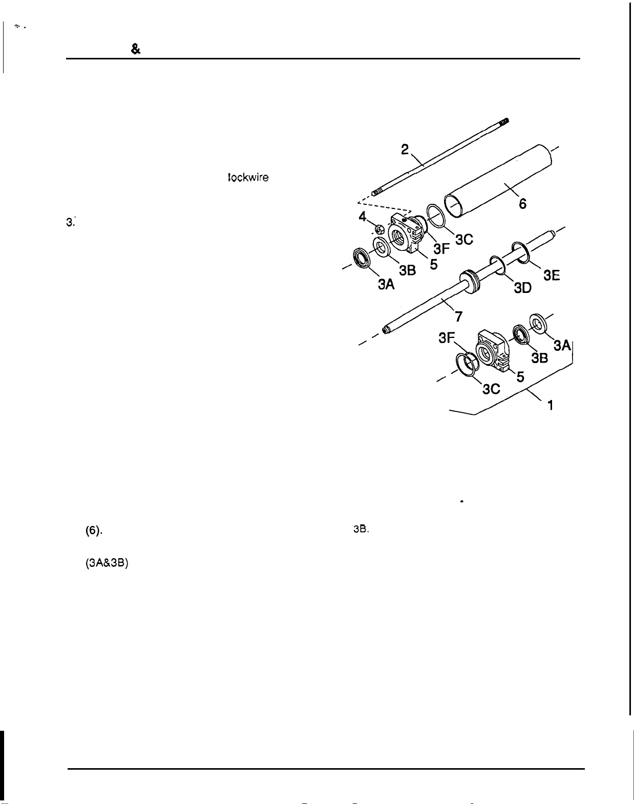
Swing Cylinder (Figure
31)
DISASSEMBLY
1.
Remove hex nuts
(4)
from tie rods
(2).
2.
Remove both piston rod guides
(5)
from barrel
3. Remove and discard rod wiper and seal
4.
Remove rod assembly (7) from barrel
(6).
5.
Clean
all
components in solvent and blow dry
(6)-
(3A&3B) from each piston rod guide.
Remove and discard seals.
with low pressure air.
ASSEMBLY
1.
Lubricate seals and wipers with clean hydraulic
fluid.
2.
Install O
-
ring
(3D)
in groove on piston and
piston seal
(3E)
on top
of
O
-
ring in piston
groove.
1.
Hydraulic swing cylinder complete
2.
7/16
x
16
"
Tie
rod
3.
Seal
kit
(contains
3A
-
3F)
3A.
Rod
wiper
38.
Rod
seal
3C.
Gland
static
seal
3D.
O
-
Ring
3E.
Piston seal
3F.
Back
-
up ring
4.
7/16
Hex
nut
5.
Piston rod guide
6.
Barrel
7.
Rod assembly
Figure
31.
Swing Cylinder
41
Loading ...
Loading ...
Loading ...