Loading ...
Loading ...
Loading ...
ASSEMBLY
INSTRUCTIONS
Control Handle Installation
(Figure
5)
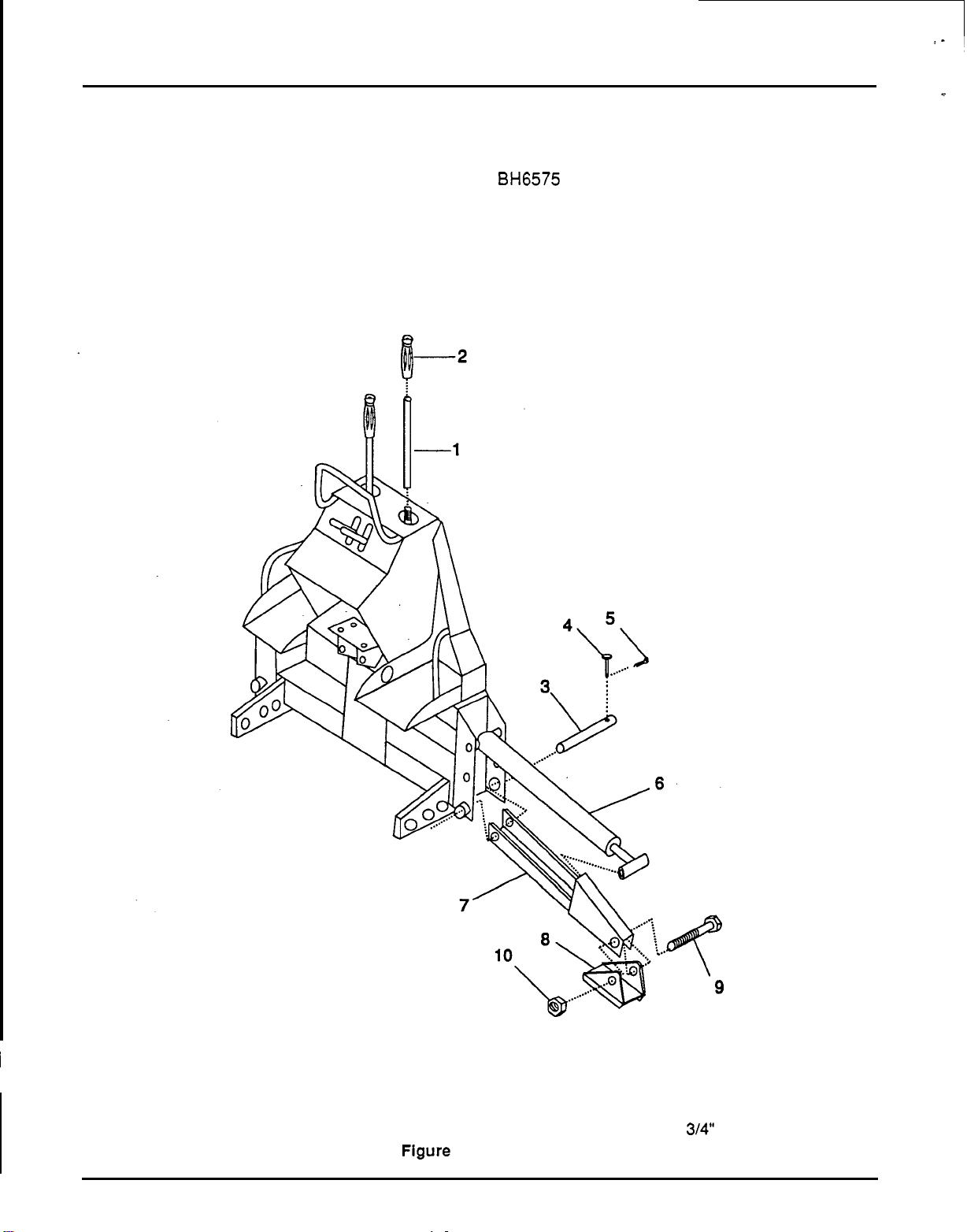
1.
Install both control handles.
Stabilizer Installation (Figure
5)
Right stabilizer (reference
7,
Figure
5)
on the
BH6575
backhoe is shipped banded.
2.
Slide a rubber grip over each control handle.
1.
Remove right stabilizer pin
(3)
and attach
stabilizer
(7).
2.
Remove bolt
(9)
from right stabilizer pad and
assemble cylinder rod end and pad to right
stabilizer.
1.
Control handle
6.
Stabilizer cylinder
2. Rubber
-
grip
7.
Stabilizer frame
3.
Right stabilizer pin
8.
Stabilizer pad
4.
Clevis pin
9.
Stabilizer
bolt,
3/4
NC
x
6
5.
Cotter pin
10.
Stabilizer pad nut,
314"
NC locknut
Figure
5.
Stabilizer Installation
I
16
Loading ...
Loading ...
Loading ...