Loading ...
Loading ...
Loading ...
..
ASSEMBLY
INSTRUCTIONS
H
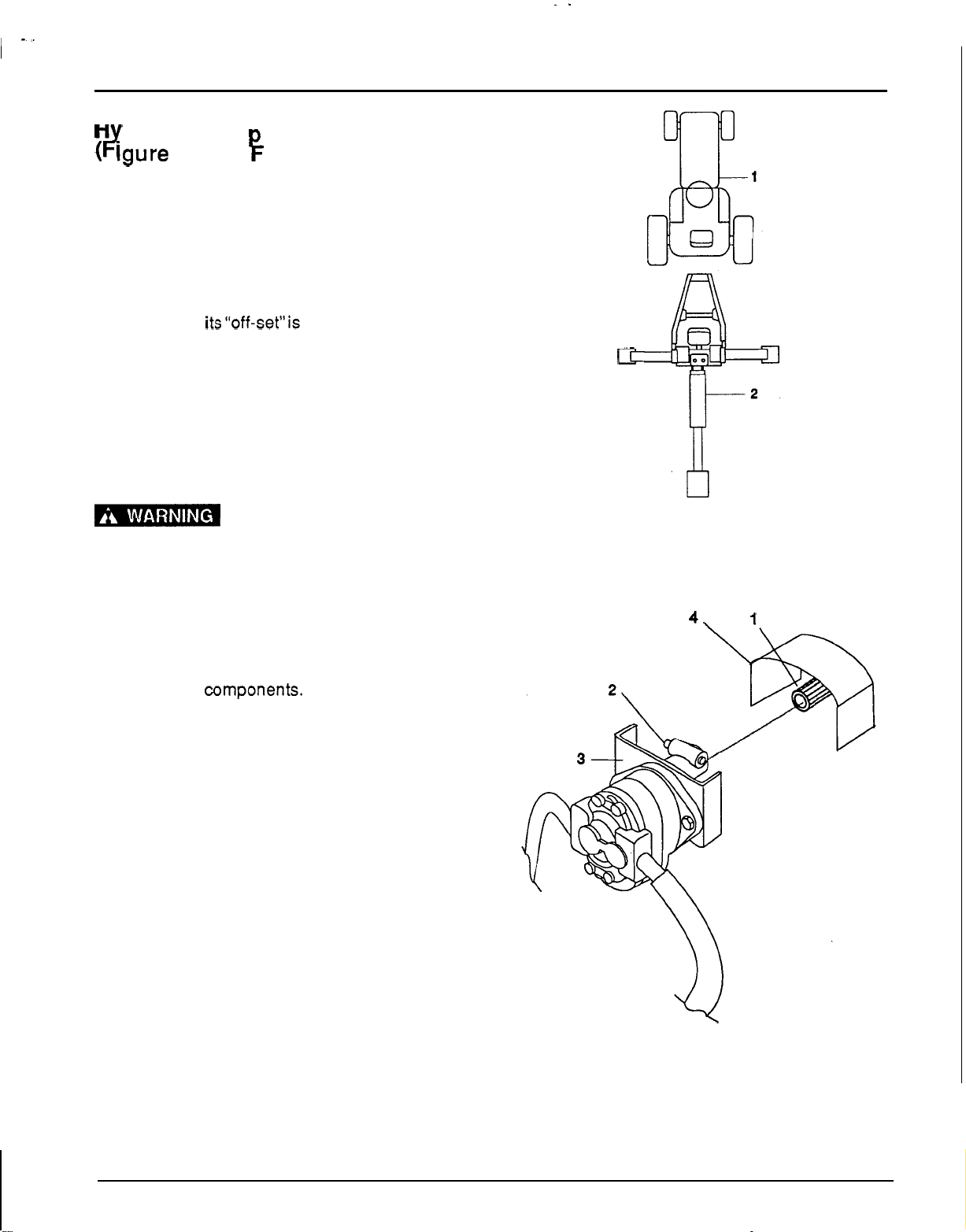
draulic Pum Installation
#
lgure
11
and
F
igure
12)
1. Check all hydraulic fittings and lines to
be
sure
they are tight and free of kinks and twists.
2.
Back the tractor as near as possible and center
on backhoe. See Figure 12.
3.
The pump mounting bracket
(3)
is designed to
slip inside tractor’s PTO shield
(4).
Install the
bracket
so
its“off-set”is towards the tractor and
PTO.
4.
Grease the drive line sliding surfaces and slide
the female tube of the pump mounting coupler
over the male PTO shaft. See Figure 11.
5.
Check that the hydraulic pump spring activated
locking pin (2) slides freely and is seated firmly
in the tractor PTO shaft spline groove.
1-
The PTO turns at
540
RPM.
If
the coupler is not locked to the PTO shaft at
the tractor end, the pump assembly can fly
loose with great force, and
is
capable
of
causing serious injury
6.
Before installing the sub
-
frame to the tractor, it
may be necessary to reposition the hydraulic
hoses to remove kinks, bends or hose rubbing
on frame
components. Loosen the hydraulic
fittings at the pump or
oil
filter assembly and
hose connections.
Do
this quickly to minimize
hydraulic fluid leakage. Adjust the hydraulic
hose to obtain
a
suitable direction. Tighten all
hydraulic fittings and hose connections.
csr
1.
Tractor
2.
Backhoe
Figure
11.
Tractor
-
Backhoe
Alignment
4.
1
1.
PTO
2.
PTO
locking pin
3.
Pump mounting bracket
4.
PTO
shield
Figure
12.
Pump Installation
23
Loading ...
Loading ...
Loading ...