Loading ...
Loading ...
Loading ...
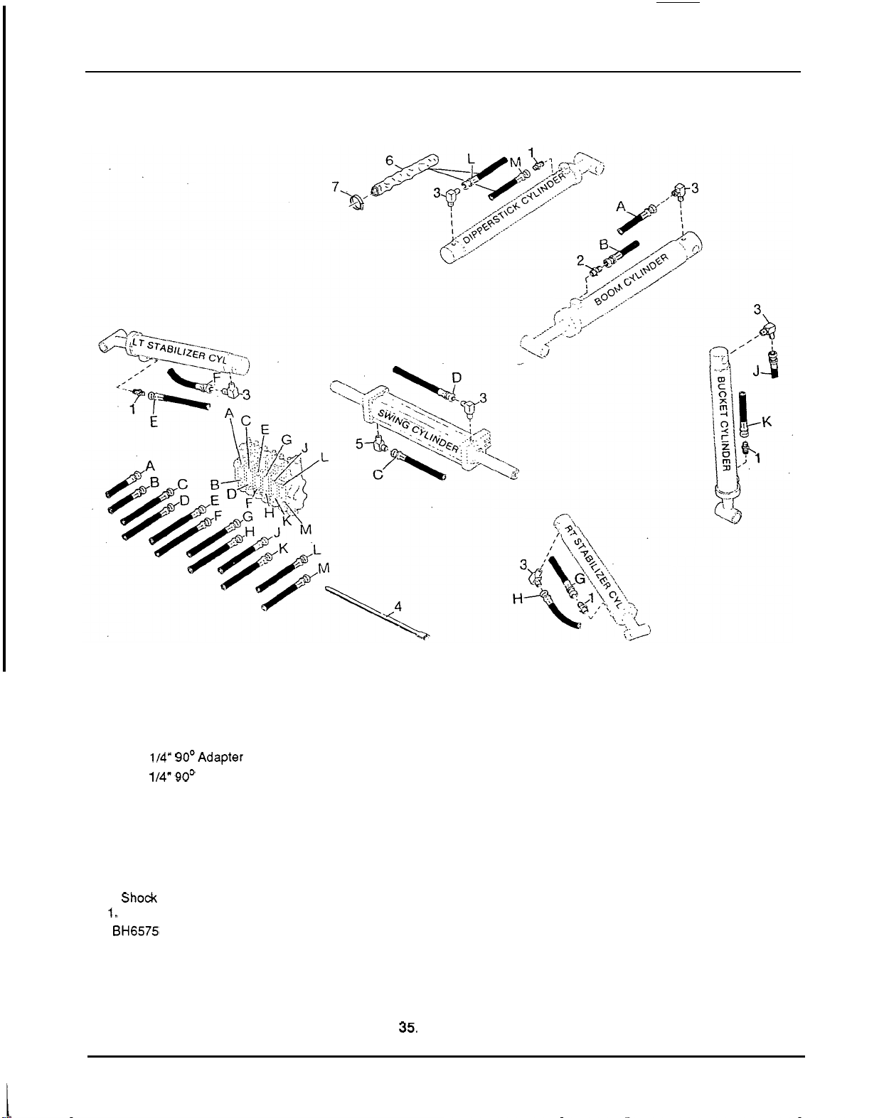
PLUMBING SCHEMATIC
PLUMBING SCHEMATIC
Use this figure and Figure 36 for plumbing
schematics. Letters are for hose
connection locations for both Figure 35
and Figure 36.
1. 114
x
114
"
Straight adapter union
3.114
x
114" 90OAdapter union
4. 114
x
114" 90' Adapter union with
5.
Relief valve
6.
Shock dampening valve, 2500 psi
7.
Shock dampening valve, 2000 psi
8.
Shock dampening valve, 2000 psi
9. Shock dampening valve, 3500 psi
10.
Shock dampening valve, 2500 psi
1
1. Shock dampening valve, 2500 psi
The
BH6575 uses a 114
x
114
"
straight
adapter union with 3/32
"
restrictor in the
rod end of the boom cylinder.
111 6
"
restrictor
LEGEND
A
from top
port
of
boom valve segment to piston end of boom cylinder
B
from bottom
port
of valve boom segment to rod end of boom cylinder
C
from top
port
of valve swing segment to bottom left
port
of swing cylinder
D
from bottom
port
of valve swing segment to top right
port
of swing cylinder
E
from top
port
of valve left stabilizer segment to rod end of left stabilizer cylinder.
F
from bottom
port
of valve left stabilizer segment to piston end of left stabilizer
G
from top
port
of
valve right stabilizer segment to rod end of right stabilizer
H
from bottom
port
of valve right stabilizer segment to piston end of right
J
from top
port
of valve bucket segment to piston end of bucket cylinder
K
from bottom
port
of valve bucket segment to rod end of bucket cylinder
L
from top
port
of valve dipperstick segment to piston end of dipperstick cylinder.
M
from bottom
port
of valve dipperstick segment to rod end of dipperstick
cylinder
cylinder
stabilizer cylinder
cylinder.
Figure
35.
Plumbing
Schematic
50
Loading ...
Loading ...
Loading ...