

INTRODUCTION
INTRODUCTION
Thank you for purchasing a BH6575 Backhoe attachment for your Honda H6522 A4 Compact Tractor
equipped with a
H6555 Front Loader. We want
to
help you get the best results from your new backhoe
and to operate it safely.
This manual covers the assembly, operation, and maintenance of the
BH6575 Backhoe. For your
convenience, a parts guide and warranty information are also included in this publication.
The illustrations in this manual are intended to serve as a reference and may not necessarily depict the
actual model listed above. The information in this publication is based on the latest product information
available at the time of printing. American Honda Motor Co., Inc. reserves the right to make changes at
any time without notice and without incurring any obligation.
This manual is a permanent part of the backhoe and must remain with the backhoe
if
resold.
No part of this publication may be reproduced without written permission.
SAFETY MESSAGES
Your safety and the safety of others are very important. We have provided important safety messages
in this manual and on the backhoe. Please read these messages carefully.
A safety message alerts you to potential hazards that could hurt you or others. Each safety message is
preceded by a safety alert symbol
A
and one
of
three words: DANGER, WARNING, or CAUTION.
These mean:
!
DL
You WILL be KILLED or SERIOUSLY HURT if you don’t follow instructions.
1-
You can be KILLED or SERIOUSLY HURT if you don’t follow instructions.
?A
0
You
can be HURT if you don’t follow instructions.
Each message tells you what the hazard is, what can happen, and what you can do to avoid or reduce
injury.
DAMAGE PREVENTION MESSAGES
You will also see other important messages that are preceded by the word NOTICE.
This word means:
-1
Your
backhoe
or
other property can be damaged if you don’t follow instructions.
The purpose of these messages is
to
help prevent damage to your backhoe, other property, or the
environment.
The Honda
BH6575 Backhoe attachment is designed
to
give safe and dependable service
if
assembled
and operated according to instructions.
If
a problem should arise, or
if
you have any questions about your backhoe, consult an authorized
Honda compact tractor dealer.
1

ATF
....
AutomaticTransmission
Fluid
CV
.......... Constant Velocity
F
....................
Female
GA
..................
Gauge
GR
(5,
etc.)
......
Grade
(5,
etc.)
NF
............. National Fine
UNF
.............
Unified Fine
PTO
..........
Power Take
Off
kg
.................
.Kilogram
ID
...........
Inside Dimension
INTRODUCTION
The chart below lists common abbreviations used throughout this
manual.
ABBREVIATIONS
P
......................
Pitch mm
................
Millimeter
M
......................
Male psi
.....
Pounds per Square Inch
Engineers
N
.................. .Newton UNC
..........
.Unified Coarse
NC
...........
National Coarse NPSM
....
National Pipe Straight
Mechanical
HT
.............
Heat Treated UNS
..........
.Unified Special
m
....................
Meter NPT
......
.National Pipe Thread
ASTM
...... American Society fo
Ib.
...................
Pound
Testing
&
Materials
R
....................
.Right
L
.......................
left
OD
........
.Outside Dimension
NOTES
MPa
............
.Mega Pascal SAE
......
Society of Automotive
2

TABLE
OF
CONTENTS
TABLE
OF
CONTENTS
INTRODUCTION
......................
1
ACCIDENT PREVENTION
................
5
GENERAL INFORMATION
................
6
SAFETY LABELS
.....................
7
SAFETY RULES
......................
9
ASSEMBLY INSTRUCTIONS
..............
11
OPERATION
.......................
26
TROUBLESHOOTING
..................
34
SERVICE
&
MAINTENANCE INSTRUCTIONS
.....
35
PLUMBING SCHEMATIC
................
50
SPECIFICATIONS
....................
52
INDEX TO PARTS LIST
.................
55
WARRANTY
.......................
71
3
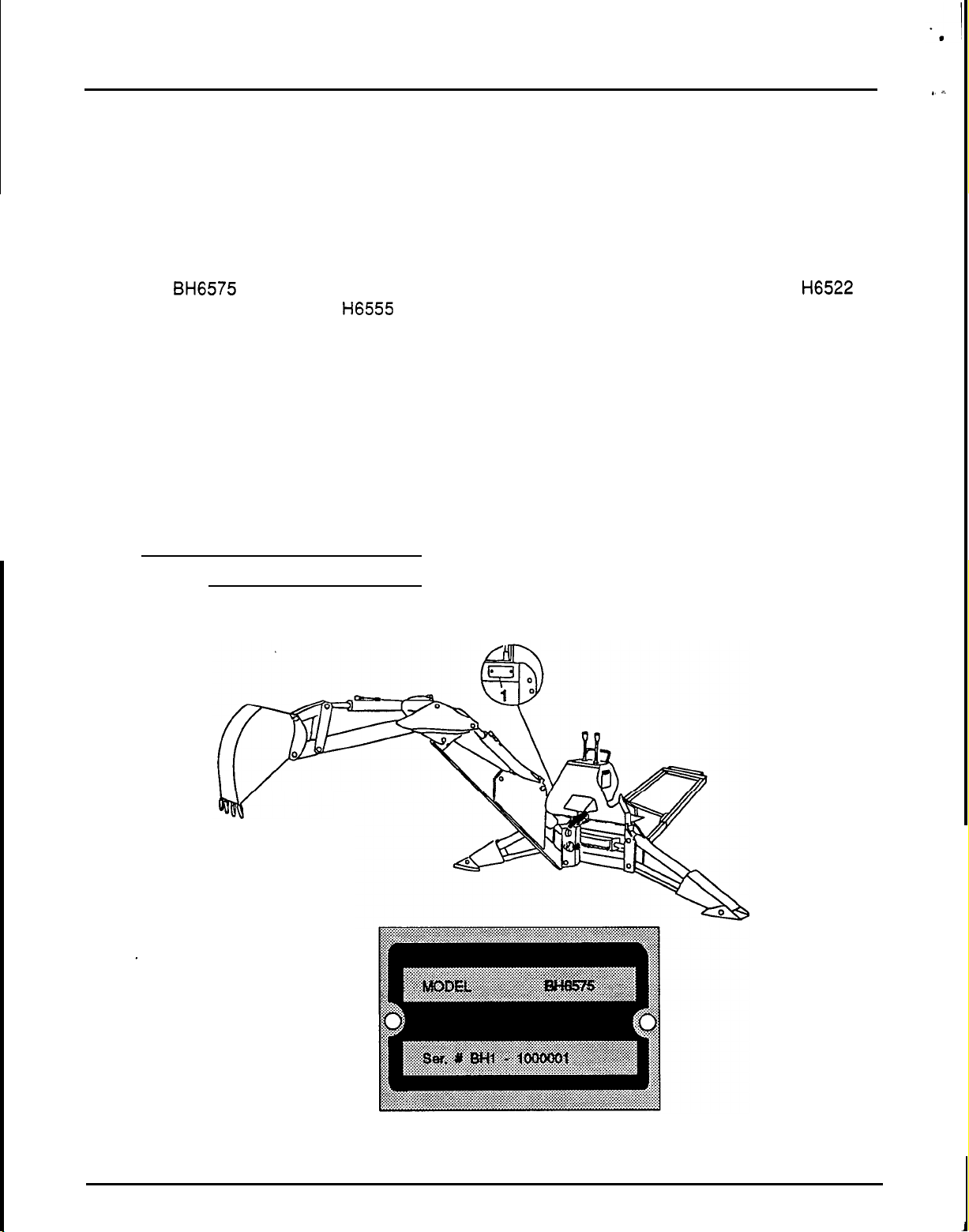
TABLE OF CONTENTS
GENERAL SAFETY INFORMATION
TO THE OWNER:
Read this manual before using your backhoe. The information presented will prepare you to do
a
better
and safer job. Keep this manual handy for ready reference. Study this manual carefully and become
acquainted with all the adjustments and operating procedures before attempting to operate your new
equipment.
The Honda
BH6575 Backhoe attachment
is
designed only for sub
-
frame mounting to
a
Honda H6522
Compact Tractor equipped with a H6555 Front Loader. It is not to be modified
or
mounted in any other
configuration.
The backhoe you have purchased has been carefully engineered and manufactured to provide
dependable and satisfactory use. Like all mechanical products,
it
will require cleaning and upkeep.
Lubricate the backhoe as specified. Observe all safety information in this manual and safety labels
on
the backhoe and tractor.
For service, your authorized Honda compact tractor dealer has trained mechanics, genuine Honda
service parts, and the necessary tools and equipment to handle all your needs.
Use only genuine Honda service parts. Substitute parts may not meet standards required
for
safe and
satisfactory operation. Record the model and serial number of your backhoe (Figure
1):
Model:
Serial Number:
Provide this information to your dealer to obtain correct repair parts.
1
Figure
1.
Model and Serial Number Location
4

ACCIDENT PREVENTION
ACCIDENT PREVENTION
Accidents Can
Be
Prevented
With
Your
Help
No
accident prevention program can be successful without the wholehearted cooperation of the person
who is directly responsible for the operation of equipment.
A
large number of accidents can be prevented only by the operator anticipating the result before the
accident is caused and doing something about it.
No
power
-
driven equipment, whether it be
transportation
or
processing, whether it be on the highway,
in
the harvest field or in the industrial plant,
can be safer than the person who is at the controls. Accidents can be prevented by operators who
accept
a
full measure of their responsibility.
It is true that the designer, the manufacturer, the safety engineer can help, but their combined efforts
can be erased by a single careless act
of
the operator.
The best kind of
a
safety device is a careful operator. We ask you to be that kind of an operator.
5
GENERAL INFORMATION
GENERAL INFORMATION
The purpose of this manual is to assist in setting
up, operating and maintaining your backhoe. Read
it carefully. It furnishes information and instructions
that will help you achieve years of dependable
performance.
These instructions have been compiled from
extensive
field
experience and engineering data.
Some information may be general in nature due to
unknown and varying conditions. However,
through experience and these instructions, you
should be able to develop procedures suitable to
your particular situation.
The illustrations and data used in this manuatwere
current at the time of printing, but due to possible
in line production changes, your machine may vary
slightly in detail. We reserve the right to redesign
and change the machines as may be necessary
without notification.
-
FORWARD
Some illustrations in this manual show the backhoe
with safety shields
or
other components removed
to provide a better view.
Operating the
backhoe
with
safety
shields
or
any components removed
could cause serious injury.
The
backhoe
should never
be
operated with any
safety
shielding
or
components removed.
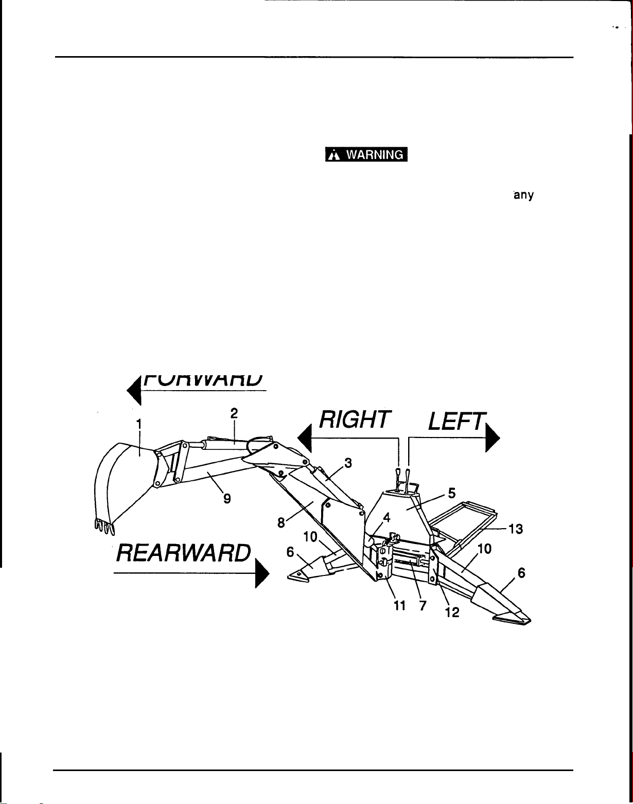
Throughout this manual, references are made to
right, left, forward and rearward directions. These
are determined from the backhoe operator seat
position facing forward as shown in .Figure
2.
Nomenclature for backhoe components have
some variations throughout the industry. We use
SAE
designations as shown in Figure
2.
1.
Bucket
2.
Bucket cylinder
3.
Dipperstick cylinder
4.
Boom cylinder
5.
Console
6.
Stabilizer
7.
Swing cylinder
8.
Boom
9.
Dipperstick
10.
Stabilizer cylinder
11.
Swing Frame
12.
Main Frame
13.
Sub
-
frame assembly
Figure
2.
Backhoe Nomenclature
6
I
-*
SAFETY
SAFETY
,
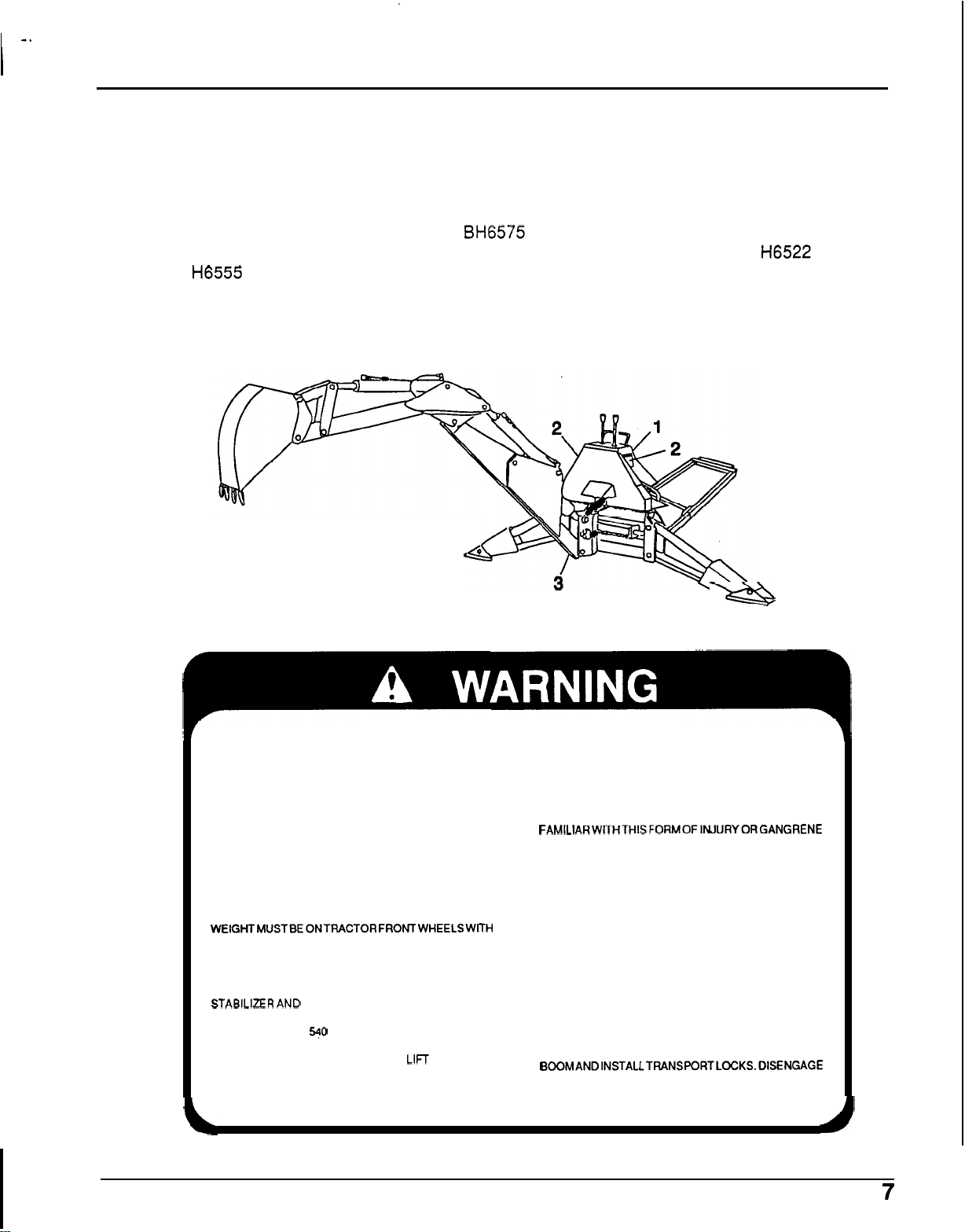
SAFETY LABEL LOCATIONS
(Figure
3)
Read all safety instructions before operating the BH6575 Backhoe. Anyone who uses the backhoe
should read and understand this information before operating the backhoe. Refer to the
H6522 Owner’s
Manual and
H6555 Front Loader Operator’s Manual
for
additional safety label information before
operating the backhoe.
The safety labels should be considered as permanent parts of the backhoe.
If
a safety label comes
off
or becomes hard to read, contact an authorized Honda compact tractor dealer for replacements.
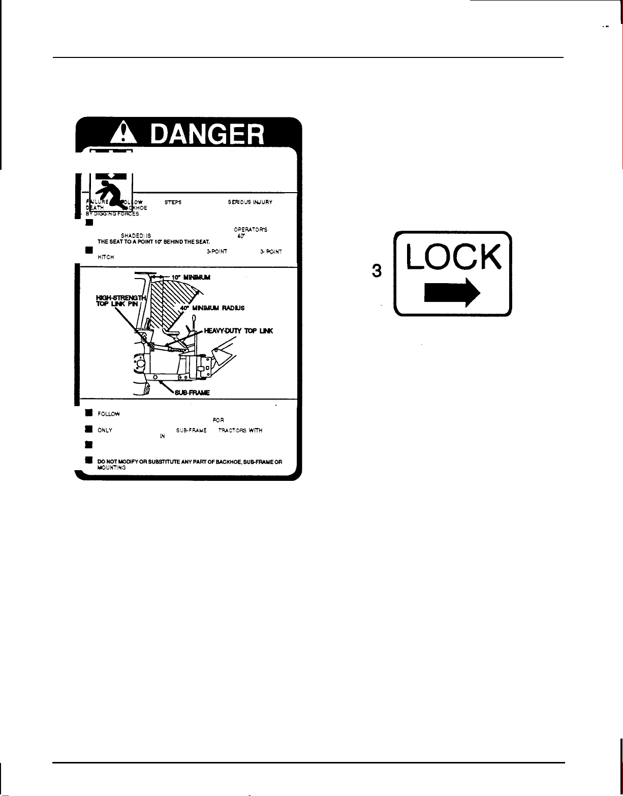
1.
Warning Label
2.
Danger Label
3.
Lock
Label
Figure
3.
Safety Label Locations
a
1
TO
AVOID
SERIOUS
INJURY
OR
DEATH,
READ OPERATOR’S MANUAL AND FOLLOW ALL
KEEP HANDS AND BODY AWAY FROM
SAFETY, OPERATING AND SERVICE INSTRUCTIONS
HIGH
-
PRESSURE LINES. IF OIL, UNDER PRESSURE,
(CONTACT DEALER FOR MANUAL.) PENETRATES THE SKIN,
IT
MUST BE SURGICALLY
ENSURE
ALL
SAFETY SHIELDS AND DECALS ARE
REMOVED WITHIN A FEW HOURS BY A DOCTOR
INSTALLED AND IN GOOD CONDITION.
FAMlLlARWITHTHISFORMOFlNJURYORGANGRENE
MAY RESULT.
DO NOT ALLOW CHILDREN
OR
UNQUALIFIED
CONSULT LOCAL UTILITIES BEFORE DIGGING. KNOW
PERSONSTOOPERATE EQUIPMENT.
LOCATION OF AND AVOID CONTACTING ALL
A MINIMUM
25%
OF TRACTOR AND EQUIPMENT
WEIGHTMUSTBEONTRACTORFRONTWHEELSWITH
UNDERGROUND CABLES, PIPELINES, OVERHEAD
WIRES AND OTHER HAZARDS IN DIGGING AREA.
BACKHOE IN TRANSPORT POSITION. NO RIDERS ARE ALLOWED ON TRACTOR
OR
WHEN OPERATING, ALWAYS SIT IN BACKHOE SEAT;
KEEP BYSTANDERS AWAY FROM OPERATOR, BEFORE TRANSPORTING, ATTACH SLOW MOVING
STABILERAND MAXIMUM BUCKET SWING AREAS. VEHICLE (SMV) SIGN AND ENGAGE TRANSPORT
OPERATE PTO AT
540
RPM
MAX.
BACKHOE.
LOCKS.
BACKHOE DIGGING FORCES CAN
LIFT AND TURN
TRACTOR OVER. MAKE SURE STABILIZER PADS ARE
ON FIRM GROUND AND AVOID
SOFT
OR
STEEP
BANKS.
BEFORE LEAVING EQUIPMENT UNATTENDED. RAISE
BOOMANDlNSTALLTRANSPORTLOCKS.0lSENGAGE
PTO, RELIEVE PRESSURE ON DIPPERSTICK AND
BUCKET. SHUT ENGINE OFF AND REMOVE KEY.
.-
I
SAFETY
2
I
151
CRUSHING
HAZARD
I
FULURE
TO
RXLOW THESE
STEPS
YAY
RESULT
IN
SERIDUB
INJURY
OR
DEATH
FROM MCKHOE BEING THRUST UPWARD. FORWARD
OR
REARWARD
BYWINOFORCES.
I
H
ONLY OPERATE WHEN MANUFACTURERS SUBFRAME AND FRONT
-
END
LOADER HAVE BEEN INSTALLED AND AWUSTED. AND
OPEIUTOWS
AREA
(SHOWN SHADED1
IS
FREE FROM OBSTRUCTIONS IN
A
UT
RAMUS
FROM
I
THESUTTOAPOlNT((rBEHlNDTHESUT
H
NEVER MOUNT BACKHOE TO
A
TRACTOR
%POINT
HITCH.
THE
9
POINT
HITCH
WILL
ROTATE
AND CAUSE
SERIOUS
INJURY
OR
DEATH.
I
H
FOW
BACKHOE AND SUBFRAME OPERATORS MANUAL MOUNTING
H
WLY MOUNT BACKHOE AND SUBFRUIE
TO
TRACTORS
WmC FRONT
INSTRUCTIONS. (CONTACT
A
HONM
DEALER
K)R
MANUAL)
WADERS
AS
SPECIFIED
IN
MANUAL
ONLY USE MANUFACTURERS HEAVY
-
DUTY TOP LINK AND
HIGHSTRENGTH TOP
UNK
PIN.
H
DONOTMODlMORSUBST~UTEANYPARTOF8*CKHOE.SUB.FRIMEOR
MOUNTING
HARDWARE.
8
I
-
SAFETY
SAFETY INFORMATION
Safety is a primary concern in the design and
manufacture of our products. Unfortunately, our
efforts
to
provide safe equipment can be erased by
a single careless act of an operator.
In addition to the design and configuration of
equipment, hazard control and accident prevention
are dependent upon the awareness, concern,
prudence and proper training of personnel involved
in the operation, transport, maintenance and
storage
of
equipment.
The best safety device is an informed, careful
operator. We ask you to be that kind of an operator.
The designed and tested safety of this equipment
depends on
it
being operated within the limitations
as explained in this manual.
TRAINING
Safety instructions are important! Read this
manual, the tractor manual and
all
safety
rules.
0
Know your controls and how to stop tractor
engine and backhoe quickly in an
emergency.
0
Operators must be instructed in and
be
capable of the safe operation of the
equipment, its attachments and all
controls.
Do
not allow anyone to operate
thisequipmentwithout proper instructions.
0
Keep hands and body away from
pressurized lines. Use paper
or
cardboard,
not body parts to check for leaks. Hydraulic
fluid (oil) under pressure will penetrate skin
causing serious injury.
0
Make sure that
ail
operating and service
personnel know that in the event hydraulic
fluid penetrates skin,
It must be surgically
removed within a few hours by a doctor
familiar with this form of injury, or gangrene
may result.
0
Do not allow children or unqualified
persons to operate equipment.
PREPARATION
0
The BH6575 Backhoe should only be used
with the Honda
H6522
A4
(4
-
wheel drive)
Compact Tractor.
0
Always wear relatively tight and belted
clothing to avoid entanglement in moving
parts. Wear sturdy, rough
-
soled work
shoes and protective equipment for eyes,
hands, hearing and head.
0
Never operate unless backhoe’s sub
-
frame
has been installed and properly mounted to
a
Honda H6522
A4
Compact Tractor
equipped with a
FL6555 Front Loader.
Do not operate backhoe unless there
Is
adequate operator clearance as shown on
safety label. (Refer to Danger Label on page
8.)
0
Always use special heavy
-
duty top link
(provided with backhoe) and original
equipment high
-
strength top link pin
(provided with tractor) to mount top link to
tractor. Use pin provided with backhoe to
mount top link to backhoe.
Ensure that backhoe is properly mounted,
adjusted and in good operating condition.
0
Ensure
all
safety labels are installed and in
good condition. (See page
7
illustrations.)
Ensure shields and guards are properly
installed and in good condition.
0
A
minimum 25% of tractor and equipment
weight must be on tractor front wheels with
backhoe in transport position. Without this
weight, the tractor could tip over causing
personal Injury or death. The weight must
be attained with a
FL6555 Front Loader,
fluid
In
the rear wheels and possibly rear
wheel weights depending on the type of
rear tire.
Ag tires
-
99
Ib (45 kg) ballast
In
each rear
tire and 75 Ib
(31.8
kg) wheel weight on each
rear wheel.
Turf or High Flotation Tires
-
170
Ib
(77
kg)
ballast
in
each rear tire.
Weigh the tractor and equipment.
Do
not
estimate.
9
~~
0
Make sure that the hydraulic pump
PTO
spring activated locking pin slides freely
and
Is seated firmly in the tractor
PTO
spline groove.
0
Before working on backhoe, extend boom
and dipperstick and place bucket on
ground. Make sure that ail system pressure
has been relieved by operating controls
before maintenance, service or
disconnecting any hydraulic lines.
Hydraulic system
leak down and failure of
mechanical or hydraulic system can cause
equipment to drop.
0
Clean all dirt, trash and grease from
operator’s platform and steps.
OPERATIONAL SAFETY
0
Consult local utilities before digging. Know
location of and avoid contacting all
underground cables, pipelines, overhead
wires and other hazards
in
digging area.
0
Keep bystanders away from operator,
stabilizer and maximum bucket swing
areas.
Operate only In daylight or good artificial
light.
0
When transporting, you must wear a seat
belt
if
your tractor
Is
equipped with a
ROPS.
0
Always comply with all state and local
lighting and marking requirements.
0
No
riders are allowed on tractor or backhoe.
0
When Operating controls, always sit in
backhoe seat.
c]
Disengage Power Take
Off
(PTO),
shift
tractor into neutral or park, and place all
controls
In
neutral before starting tractor
engine.
0
Operate tractor
PTO
at
540
rpm.
0
Always dump spoll at least
two
feet away
0
Always provide a means to exit from trench
0
Use extreme care when working close to
from opening.
If
It
is
25
feet or longer.
fences, ditches or on hillsides.
0
Be careful when swinging loaded bucket on
a hillside; always dump spoll on uphill side
of backhoe to
minimize upset possibility.
0
Always engage swing and boom transport
locks and attach Slow Moving Vehicle
(SMV)
sign before transporting backhoe.
0
Never leave equipment unattended with
engine running or with bucket
In
raised
position. Always rest bucket on ground and
remove
Ignition key before leaving tractor.
0
Do
not use backhoe for craning;
It
Is
designed for digging.
MAINTENANCE SAFETY
0
Always wear relatively tight and belted
clothing to avoid entanglement
in
moving
parts. Wear sturdy, rough
-
soled work
shoes and protective equipment for eyes,
hands, hearing and head.
c]
Never perform service or maintenance with
tractor engine running.
Before working on backhoe, extend boom
and dipperstick and place bucket on
ground. Make sure that all system pressure
has been relieved by Operating controls
before maintenance, service or
disconnecting any hydraulic lines.
Hydraulic system leak down and failure
of
mechanical or hydraulic system can cause
equipment to drop.
0
Keep all persons away from operator
control area while
performing adjustments,
service or maintenance.
0
Tighten all bolts, nuts and screws, and
check that all cotter pins are Installed
securely to ensure backhoe
Is
In
a safe
condition before operating.
0
Ensure all safety labels are installed and
in
good condition. (See page
7
Illustration.)
0
Ensure shields and guards are properly
installed and in good condition.
STORAGE
0
Refer to Removing and Storing Backhoe on
page
33.
10
.
..~..,<<
ASSEMBLY INSTRUCTIONS
ASSEMBLY INSTRUCTIONS
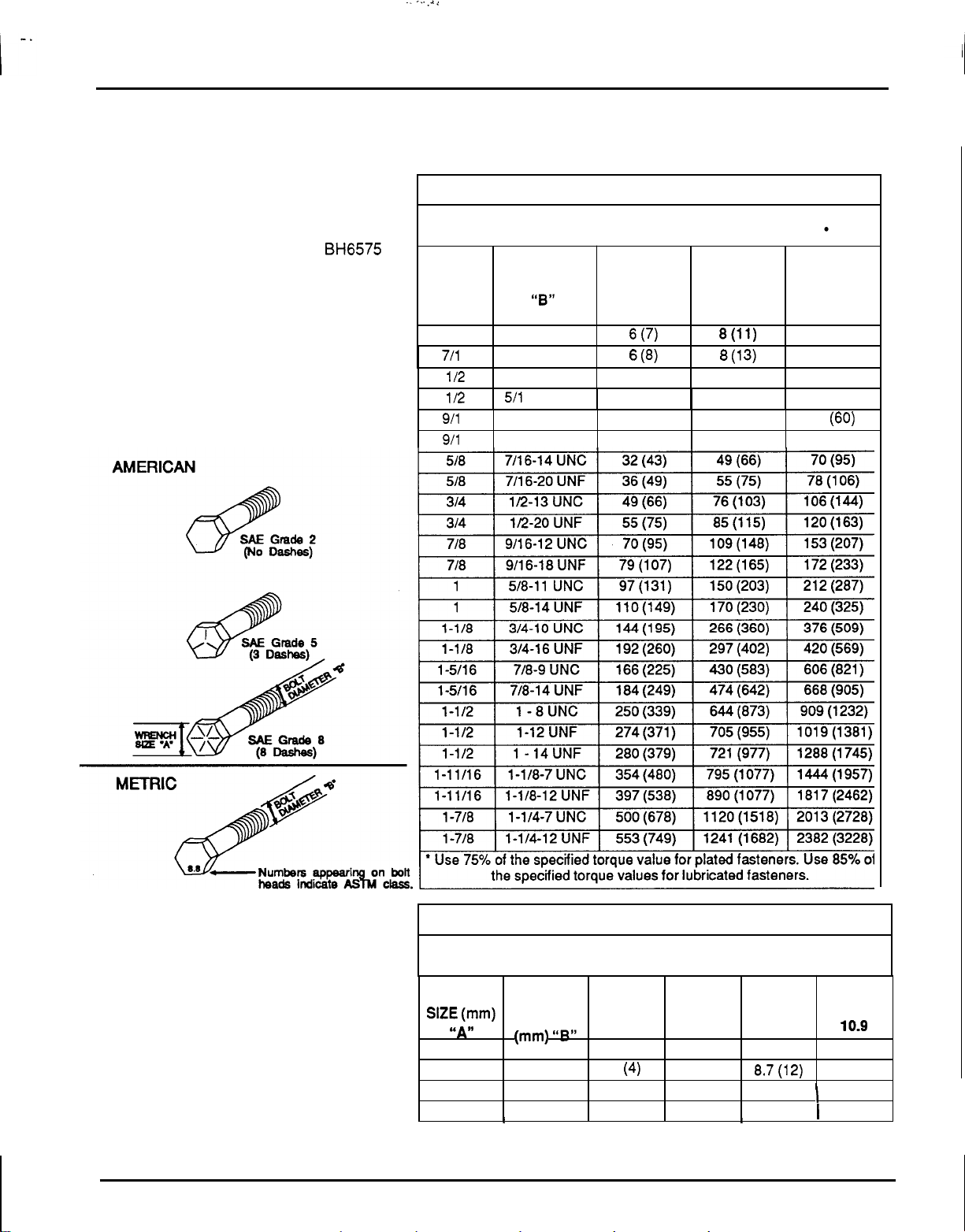
PROPER TORQUE FOR
FASTENERS
TORQUE SPECIFICATIONS (AMERICAN)
Proper torque for American fasteners used on Honda equipment.
Recommended Torque in Foot Pounds (Newton Meters).
WRENCH
GRADE
8
GRADE
5
GRADE
2
DIAMETER
SIZE (IN.)
SAE
SAE SAE
BOLT
“A”
THREAD SIZE
(IN.)
“8”
AND
7/16
12 (16)
8(11)
6 (7)
1/4
-
20 UNC
711 6
14 (18)
8
(1 3) 6
(8)
1/4
-
28 UNF
112
25 (33)
17 (23)
11 (15)
5/16
-
18 UNC
1/2
27 (37)
19 (26) 13 (1 7)
511 6
-
24 UNF
The chart lists
the
correct tightening torque
for fasteners used on the Honda
BH6575
backhoe. When
bolts
are
to
be tightened or
replaced, refer to this chart
to
determine the
grade of
bolts
and the proper torque except
when specific torque values are assigned in
manual text.
Bolt
Head Markings
911 6
44
(60)
31 (42)
20
(27)
3/8
-
20 UNC
911
6
49 (66)
35 (47)
23 (31)
3/8
-
24 UNF
TORQUE SPECIFICATIONS (METRIC)
Proper torque for Metric fasteners used on Honda equipment.
Recommended Torque in
Foot
Pounds (Newton Meter).
WRENCH
CLASS CLASS
CLASS CLASS
DIAMETER
SlZE(mm)
ASTM ASTM
ASTM ASTM BOLT
‘SAW
(mm) UBlS
4.6
10.9
9.8
8.8
8
11.1 (15) 8.7(12)
3
(4)
6 10
6.5
(8.8)
5.1 (6.9)
1.8 (2.4)
5
12
21.1 (29)
1
27
(37)
7.3 (1
0)
8
14
42 (57)
I
53 (72) 14.5 (20)
10
I
I
I I
I
I
11
ASSEMBLY INSTRUCTIONS
GENERAL ASSEMBLY
INSTRUCTIONS
Backhoe assembly is the responsibility of the
Honda Power Equipment Compact Tractor Dealer.
The backhoe should be delivered to the owner
completely assembled, lubricated and adjusted for
normal operating conditions.
Set up with these instructions and illustrations.
!
BA
When finished with
assembly, complete the following check
lists.
Failure
to
complete
all
checklists could cause
serious injury
or
death
to
the operator.
Pre-Deliveiy Check List
Inspect the backhoe thoroughly after assembly
to
be certain it is set up properly before delivering
it
to the customer. The check lists are a reminder of
points to inspect. Check
off
each item as it is found
satisfactory or after proper adjustments are made.
Check all bolts to be sure they are tight.
c]
Check that all lubrication points have been
lubricated.
c]
Check that all cotter pins and safety pins are
properly installed.
Check that the 'backhoe and sub
-
frame are
properly attached to tractor and front end
loader sub
-
frame.
c]
Check that
all
adjustments have been made.
c]
Check that hydraulic reservoir has been
serviced and that hydraulic system and all
functions have been operated through full
cylinder stroke to purge air from system.
0
Make sure
all
hydraulic fittings are tight and
there are no leaks in hydraulic system.
0
Refer to the safety instructions on pages
9
and
10
before checking for hydraulic leaks.
Delivery Check List
c]
Show customer how to make adjustments.
c]
Explain importance
of
lubrication and show
lubrication points to customer.
c]
Give Operator's Manual to customer and
recommend that all operators become familiar
with all sections and especially the safety
information.
Daily Check List
Check that the backhoe and .sub-frame are
properly and securely attached to the tractor
and front end loader sub
-
frame.
During inspection, check that all nuts and bolts
are secure and clevis pins are properly cotter
pinned.
0
Check for hydraulic leaks, frayed or worn hoses
and general safety of hydraulic system.
Refer
to
the safety
Instructions
on
page
9
and
10
before checking
for hydraulic leaks.
12
ASSEMBLY INSTRUCTIONS
DEALER SET
-
UP INSTRUCTIONS
The backhoe is shipped partially assembled.
Assembly will be easier
if
components are aligned
and loosely assembled before tightening
hardware.
Recommended torque values for hardware are
given on page
11.
vr
e
Always wear relatively tight
and
belted clothing to avoid entanglement in
moving parts. Wear sturdy, rough
-
soled work
shoes and protective equipment for eyes,
hands, hearing and head.
-
I
-
Keep all persons away from
operator control area while performing
adjustments, service or maintenance.
Keep hands and body away
from pressurized lines. Use paper or
cardboard, not body parts to check for
leaks.
Hydraulic fluid (oil) under pressure will
penetrate skin causing serious Injury.
3
Make sure that all operating
and service personnel know that In the event
hydraulic fluid penetrates skin, it must be
surgically removed within a few hours by
a
doctor familiar with this form of injury, or
gangrene may result.
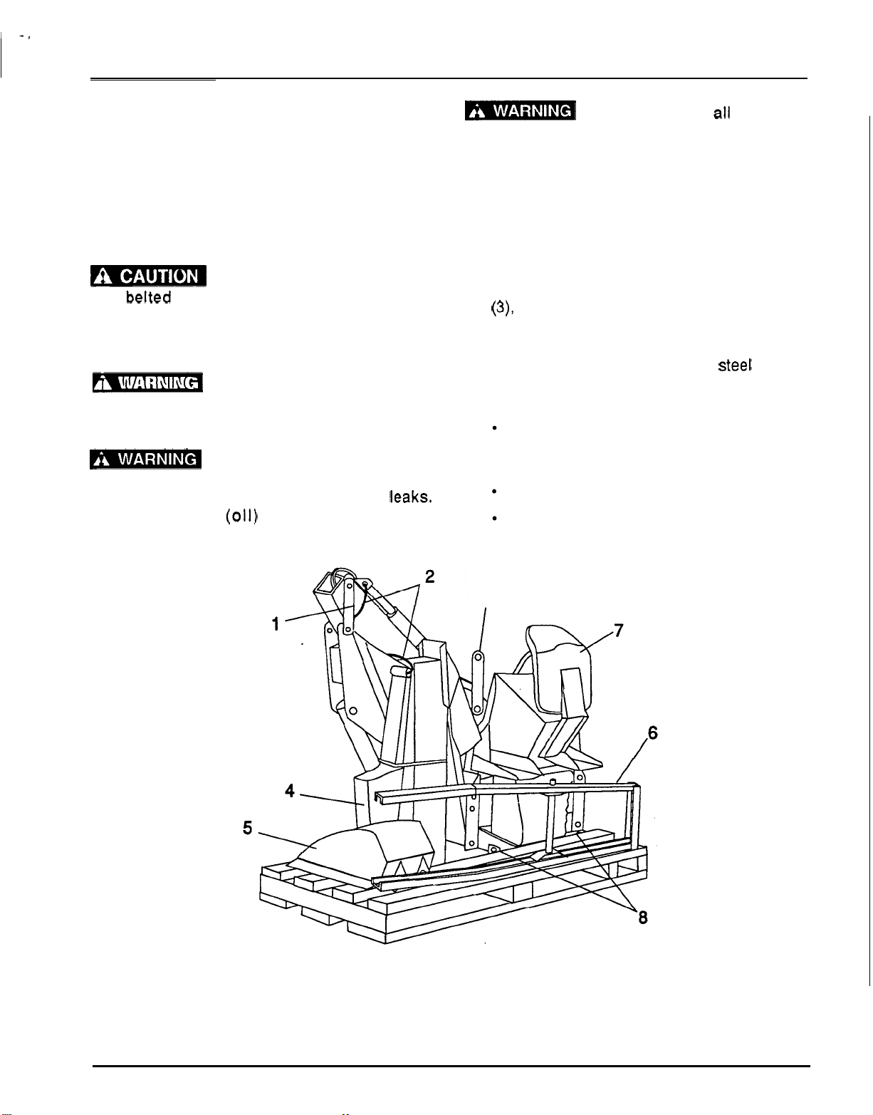
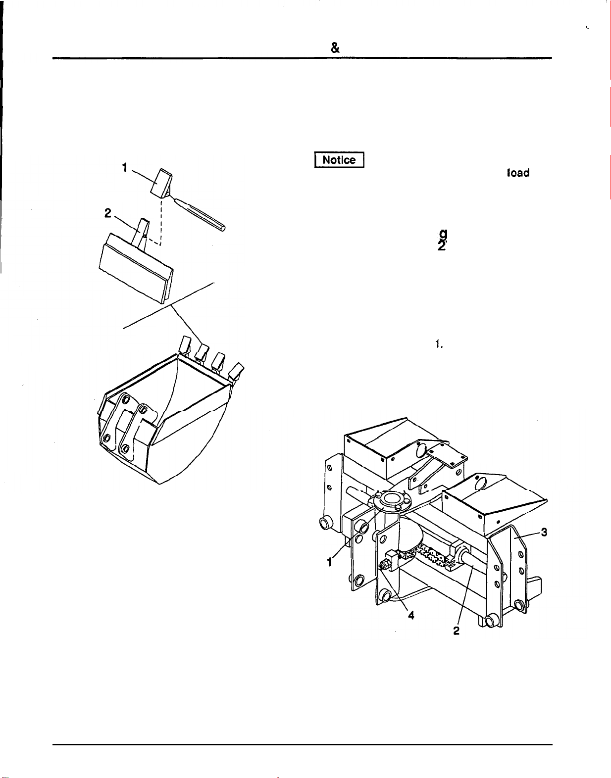
SHIPPING PALLET PREPARATION
1.
Position backhoe on pallet in an assembly
area. Support unit with
a
chain hoist from lift lug
(3),
Figure
4,
to provide stability.
2.
Remove the seat assembly from the backhoe.
3.
Remove
all
bands, tie straps
and
steel wire
(2)
from backhoe components. Set the following
components
off
the pallet for installation later.
Sub
-
frame assembly
(set
plate assembly,
cross member and upper link are
attached to the sub
-
frame).
Bucket
Right Stabilizer assembly
1.
Shipping bar
5.
Bucket
2.
Shipping bands
6.
Sub
-
frame assembly
4.
Right
stabilizer
8.
Shipping angles
Figure
4.
Backhoe
in
Shipping Configuration
3.
Lift
lug
7.
Seat assembly
13
-
~ ~~~~
~~
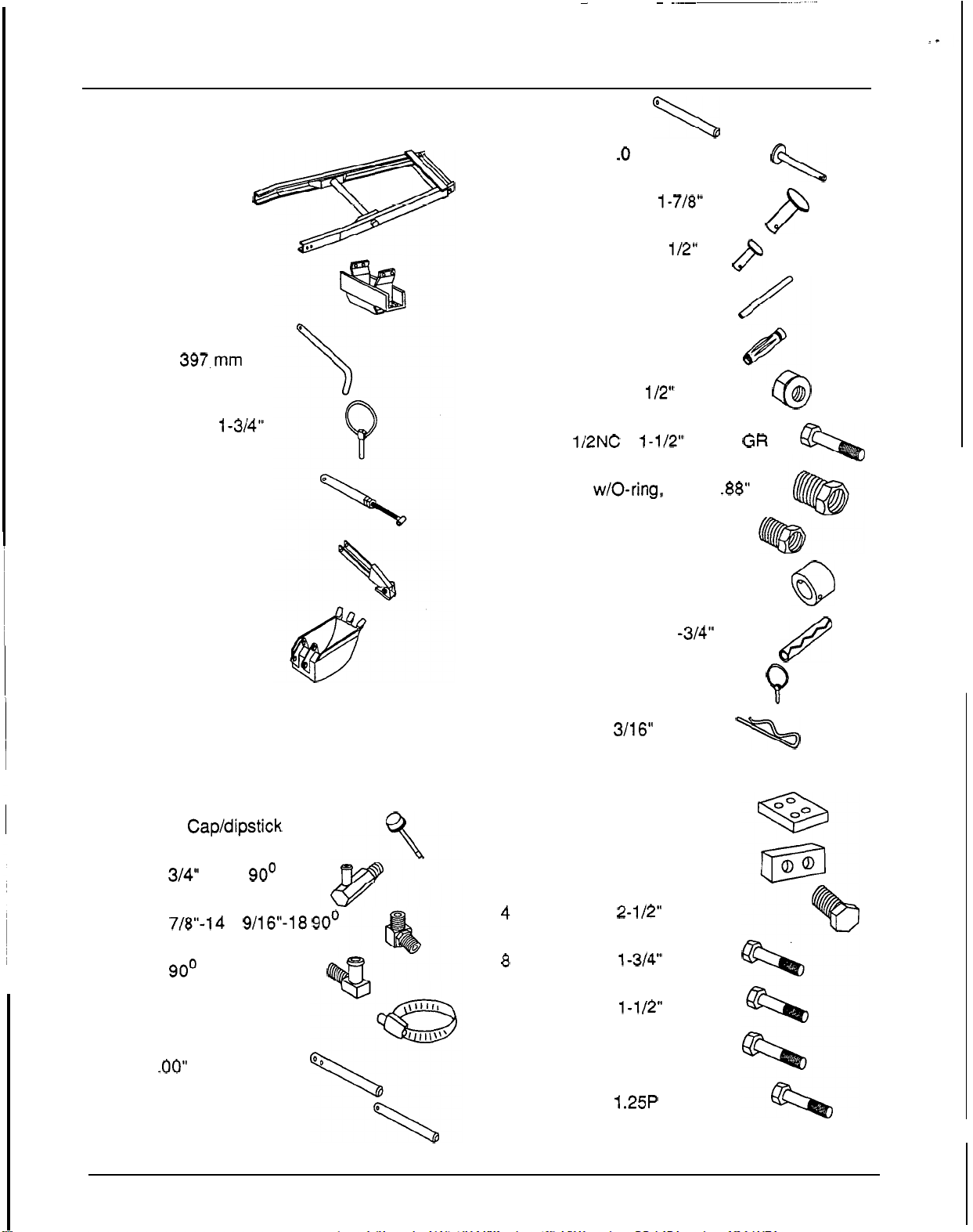
ASSEMBLY
INSTRUCTIONS
Pallet Parts
1 Crossmember
Assy.
1 Pin, 19
x
397.mm
1 Klik Pin, 1/4
x
1-3/4"
1 Upper Link
Assy.
1 Right Stabilizer
Assy.
1 Bucket
1 Sub
-
Frame
assy.
4. Open the parts box and lay parts out to make
location easy. Refer to parts list and the
illustrations below.
14
"
x
18
"
Double
Burlap Bag
1 Breather Cap/dipstick
1 Elbow, 314 Hose 90'
1 Elbow, 7/8"-14
x
9/16"-18 90'
1 Fitting, 90'
2 Screw Hose Clamps
1 Pin,
1
.OO"
x 6.19
"
HT
1 Pivot Pin (boom)
1
2
2
2
2
2
2
2
1
1
2
2
1
1
Pivot Pin
\
Pivot Pins, 1
.O
x
7.25
"
WA
\
Clevis Pins, 1/4
x
1-718"
Clevis Pins, 1/16
x
1/2"
Control Handles
8
Grips (black)
Hex Lock Nuts,
1/2" NC
Bolts,
1/2NC
X
1-1/2" HHCS
GR
5
Reducer w/O-ring, 1.31
x
.88"
Reducer O
-
ring Boss
Pivot Pins Retaining Sleeve
Spiral Pins, 5/16
x
1 -3/4"
Swing Lock Pin
Safety Pin,
3/16"
0
@
Q
\
Burlap Bag
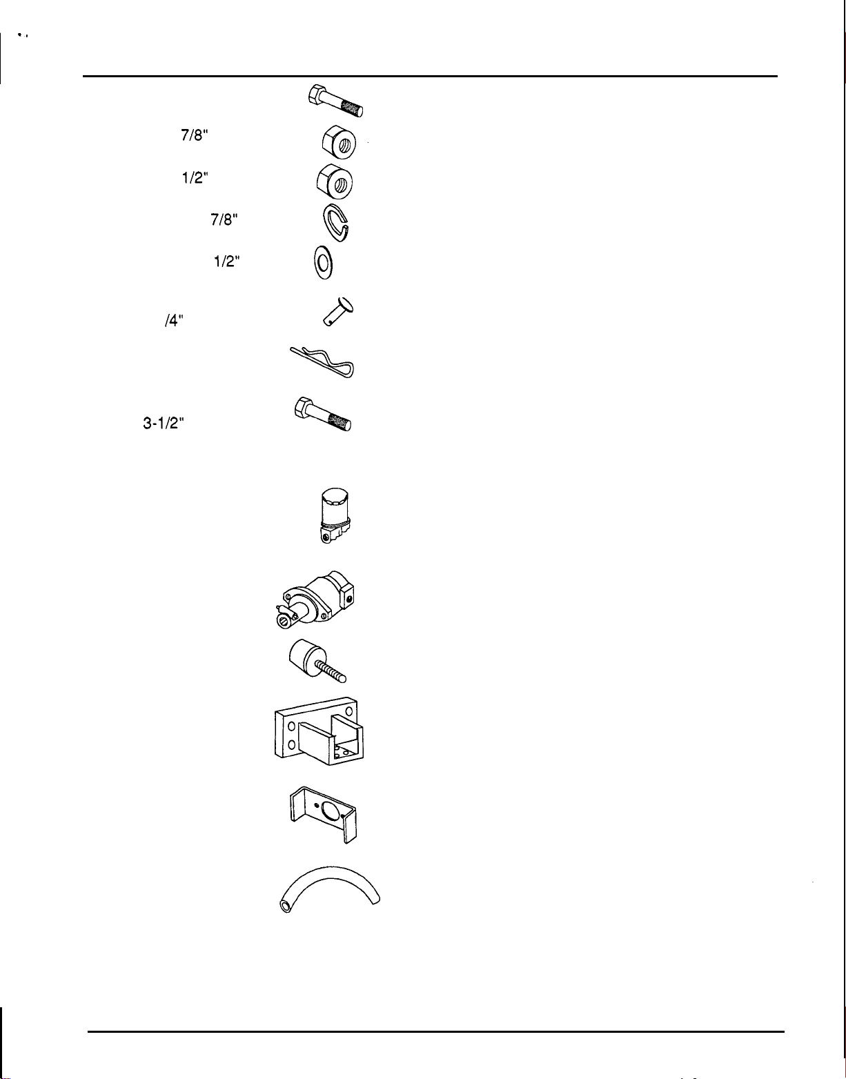
2 4
-
hole Backing Plates
2 2
-
hole Backing Plates
4 Bolts, 7/8
X
2-1/2" NC GR
5
8 Bolts, 1/2
X
1-3/4" NC
8 Bolts, 1/2
X
1-1/2" NC
4 Bolts, 12
x
80 mm
4 Bolts, 12
x
1.25P
x
35 mm
14
-,
ASSEMBLY INSTRUCTIONS
4
Bolts, 1/2
x
2
"
NC
4
Lock Nuts,
7/8"
NC
8
Lock Nuts, 1/2" NC
4 Lock Washers,
7/8"
32 Flat Washers, 1/2"
1 High strength Clevis Pin,
.
63
63
Q
0
\
3/4
X
3
-
1
14"
P
1 Safety Pin, 3/16
"
1 Backhoe Top Link Bolt,
3/4
X
3-1/2" NC
GR5
Loose
Parts
(Box)
1 Oil Filter Assy.
(in
box)
1
Pump Assy.
2
Bumper Pads
2
Crossmember
Mounting Brackets
1 Pump Mounting
Bracket
1 Hose, 3/4
ID
x
40
"
Q
15
ASSEMBLY
INSTRUCTIONS
Control Handle Installation
(Figure
5)
1.
Install both control handles.
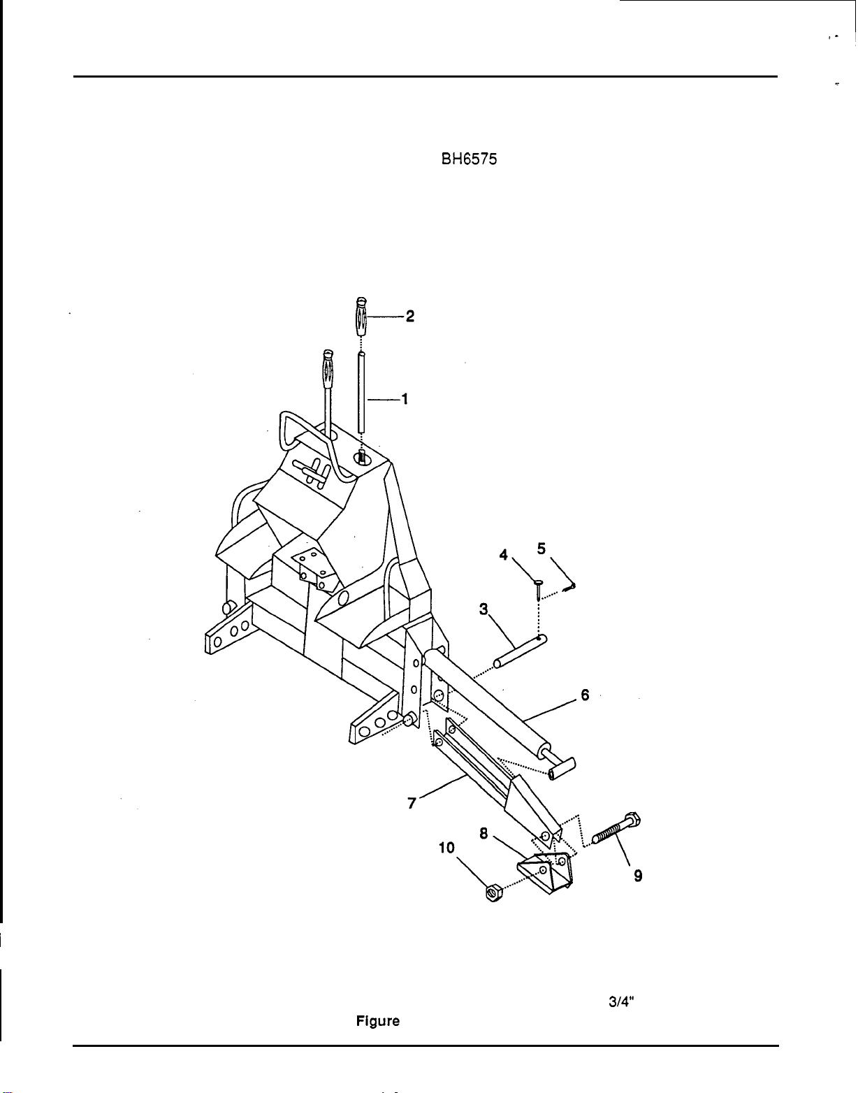
Stabilizer Installation (Figure
5)
Right stabilizer (reference
7,
Figure
5)
on the
BH6575
backhoe is shipped banded.
2.
Slide a rubber grip over each control handle.
1.
Remove right stabilizer pin
(3)
and attach
stabilizer
(7).
2.
Remove bolt
(9)
from right stabilizer pad and
assemble cylinder rod end and pad to right
stabilizer.
1.
Control handle
6.
Stabilizer cylinder
2. Rubber
-
grip
7.
Stabilizer frame
3.
Right stabilizer pin
8.
Stabilizer pad
4.
Clevis pin
9.
Stabilizer
bolt,
3/4
NC
x
6
5.
Cotter pin
10.
Stabilizer pad nut,
314"
NC locknut
Figure
5.
Stabilizer Installation
I
16
ASSEMBLY
INSTRUCTIONS
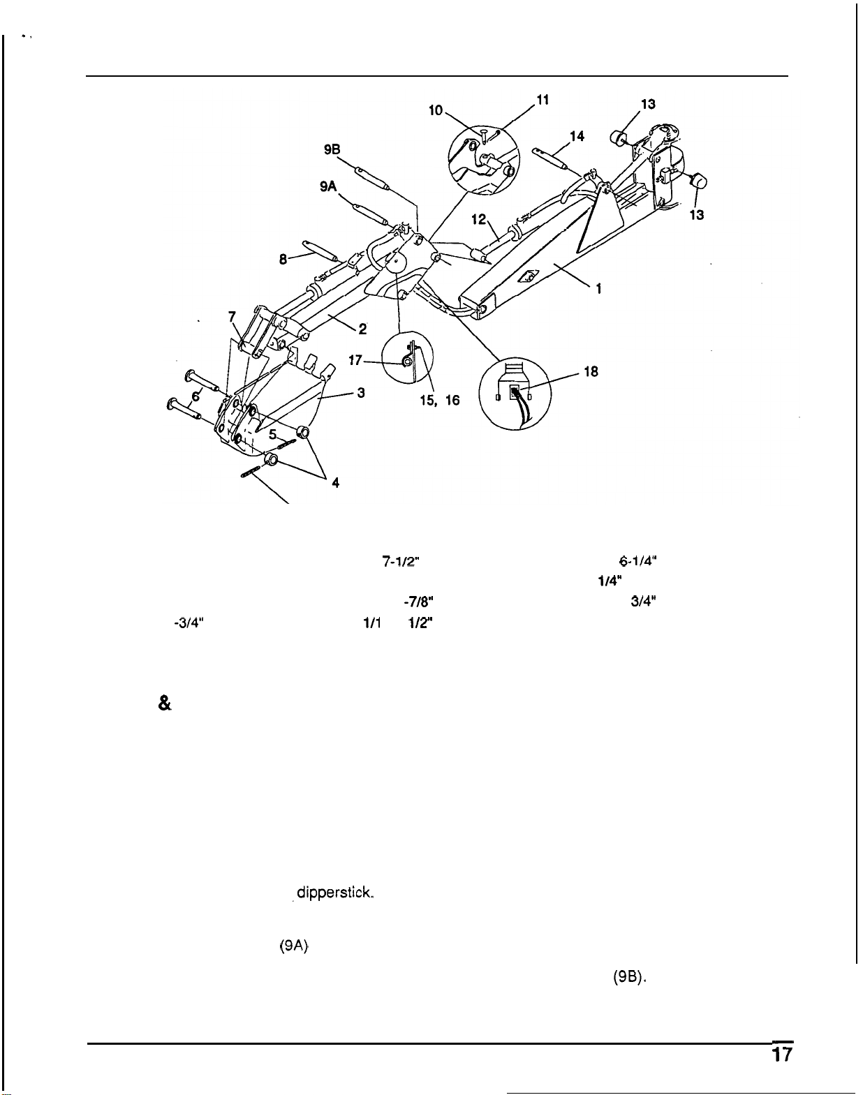
'5
1.
Boom
7.
Bucket arm
13.
Bumper pad
2.
Dipperstick
8.
1
x
7-1/2"
Pivot
pin
14.
1
x
6-1"'
Pivot
pin
3.
Bucket
9.
1
x
4
-
7/8
Pivot
pin
15. 1/4"
Flange locknut
4.
Retaining
sleeve
10. 1/4
x
1
-7/8"
Clevis
pin
16. 1/4
x
3/4"
Bolt
5.
5/16
x
1
-3/4"
Spiral pin
11. 1/1
6
x
1/2"
Cotter
pin
17.
Hose
clamp
6.
Rotating pivot pin
12.
Dipperstick cylinder
18.
Hydraulic
hose
routing
Figure
6.
Dipperstick
&
Bucket Assembly
4.
Bucket
&
Dipperstick
Installation
(Figure
6)
1. Remove shipping bar and attaching hardware
(Figure
4,
reference
1).
2.
Align dipperstick
(2)
with boom (1). Join them
with pivot pin
(8).
Line up the pivot pin hole with
hole in pivot bushing and secure with clevis pin
(1
0)
and cotter pin (1 1).
3.
Disconnect bucket hydraulic cylinder base end
where it attaches to the
,dipperstick. Route
bucket cylinder hoses through dipperstick
openings (1
8).
Make sure hoses are not
twisted. Install pivot pin
(9A) and secure with
clevis
pin
(1
0)
and cotter pin
(1 1).
5.
Fasten the bucket rod end hose (orange mark)
with the clamp (17) on the right side of the
dipperstick as shown. Leave 16
"
of hose
toward the rod end fitting past the clamp. Snug
bolt
(16) and locknut (15) but do not torque
down. Fasten bucket base end hose (white
mark) with clamp on left side
of
the dipperstick,
leaving 16
"
of hose extending toward the base
end fitting past the clamp. Snug bolt (16) and
locknut (15) but do not torque down. When
backhoe is installed on tractor, operate
dipperstick through the entire range of
movement and check that hose length beyond
the clamp is sufficient. After completing check,
tighten both hose clamps.
Align dipperstick cylinder
(12)
with dipperstick
and install pivot pin
(9B). Line up pivot pin hole
with hole in pivot bushing. Secure with clevis
pin (10) and cotter pin (1 1).

6.
7.
8.
9.
Actuate swing control handle and move boom
and dipperstick to the centered position. Lower
dipperstickand align bucket and bucket arm (7)
and install rotating pivot pin
(6).
Secure with
retaining sleeve (4) and spiral pin
(5).
Align
bucket with dipperstick and secure with
retaining sleeve (4) and spiral pin
(5).
Lower
boom and dipperstick, resting bucket on
ground.
Remove lifting lug
(3), Figure 4, from boom and
install pivot pin
(14), Figure
6.
Line up pivot pin
hole with hole in pivot bushing. Secure with
clevis pin (1
0)
and cotter pin (1 1).
Install rotating pivot pins
(6)
and secure with
retaining sleeves (4) and spiral pins
(5).
Install bumper pads
(13)
to kingpost as shown.
Plumbing Installation (Figure
7.)
Keep hands and body from pressurized lines. Use
paper
or
cardboard, not body parts, to check for
leaks.
Hydraulic oil under
pressure will penetrate the skin causing
serious injury.
Make sure that all operating and service
personnel know that
In the event hydraulic fluid
penetrates skin,
It
must be surgically removed
within a few hours by a doctor familiar with this
form of injury, or gangrene may result.
To prevent damage to the
hydraulic system:
Clean all fittings and use care to prevent
foreign
material from entering hydraulic
system.
Additional sealant such as pipe dope or
Teflon thread tape is not required on O
-
ring
fittings.
Teflon thread tape
Is
recommended for pipe
threads. Use care when applying to prevent
excess tape from entering hydraulic
system.
Make sure all hydraulic connections are
tight and all hydraulic
lines
and hoses are
In
good condition before engaging the
tractor PTO.
ASSEMBLY
INSTRUCTIONS
1. Apply Teflon tape to the reservoir filter fitting.
2.
Install filter base inlet port
-
to reservoir fitting.
Install elbow (4) in outlet port of filter base. Ideal
orientation of the filter is vertical; position filter
base to accommodate this location. The filter
may be moved to provide clearance when
attaching backhoe to tractor
if
necessary.
Install filter in filter base.
3.
To
properly install hydraulic fittings with
O
-
rings, completely loosen locknut, screw
fitting completely in, hold in position and tighten
locknut using
two
wrenches.
4. Check pump reducers and elbows for O
-
rings
before installing them.
5.
Install reducer (1 1) in pump suction port.
6.
Install
90’
elbow (10) into reducer
(1
1).
7.
Install reducer (13) into pump pressure port.
Install elbow (14) into reducer (13).
8.
Attach one end of suction hose
(6)
to elbow (4)
at the filter and the other end to elbow (10) at
the pump and secure with hose clamps
(5).
9.
Attach hose (1
5)
to elbow (1 4).
10. When backhoe is attached to tractor, it may be
necessary to reposition filter and hoses to
eliminate interference.
11.
Service hydraulic reservoir by filling
to
“full”
mark on dipstick (approximately
5
to 5
-
1/2 US
gallons) with Dexron
II
ATF. When backhoe
is
mounted and operated, filling cylinders, it will
be necessary to add fluid to the reservoir.
(1
Fill with clean oil.
Do
not mix oil
types or grades.
Using unsuitable hydraulic oil
can damage the hydraulic system.
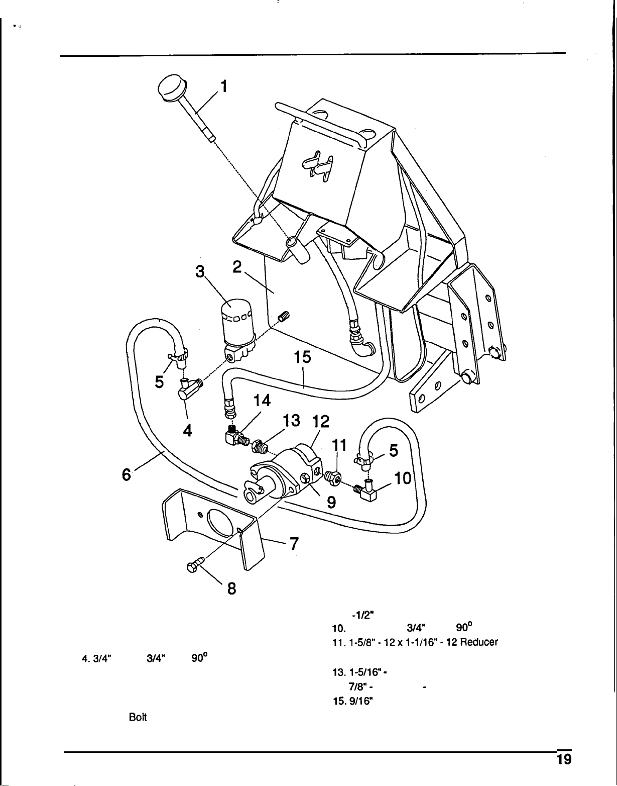
ASSEMBLY
INSTRUCTIONS
1. Dipperstick and breather
2. Reservoir
3. Fitter and housing
4.3"' Hose
x
3/4" pipe, 90' elbow
5.
Hose clamp
6. 3/4
x
36
"
Low
-
pressure hose
7.
Pump mounting plate
8. 1/2
x
1
"
Bo#
9. 1 -1/2" Locknut
10. 1
-
1/16
-
12
x
3/4" Hose, 90' elbow
11.1-5/8"-12x1-1/16-12Reducer
12. Pump
13.1-5/16
-
12
x
7/8
-
14 Reducer
14.
7/8"
-
14
x
9/16
-
18 Flare Elbow
15.9/16
-
18 Flare 34
"
High
-
pressure hose assembly
Figure
7.
Pump Installation
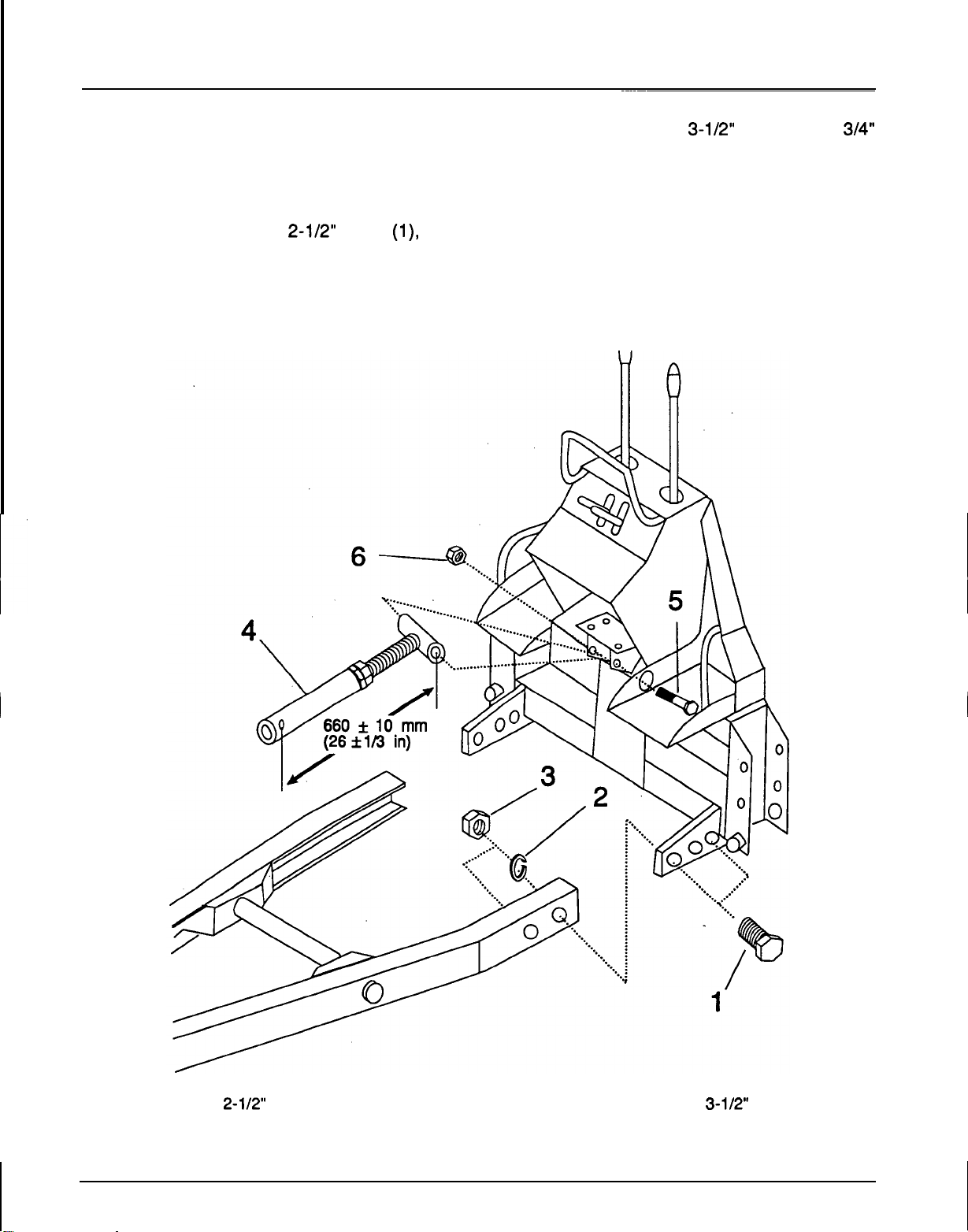
3.
Install the threaded end of the upper link
(4)
locknut
(6).
Loosen the threaded end jam nut
1.
Remove the hardware securing the backhoe to and adjust to the dimension shown for easier
the pallet (reference
8,
Figure
4).
.installation during backhoe
-
to
-
tractor
2.
Install the sub
-
frame to the backhoe as shown installation.
using the. four
7/8
x
2-1/2"
bolts
(l),
lock
washers
(2)
and nuts
(3).
Tighten to the
specified torque.
~~~~~
Sub
-
frame Installation (Figure
8)
using the
3/4
NC
x
3-1/2"
bolt
(5)
and
3/4"
A
ASSEMBLY
INSTRUCTIONS
1.
718
X
2-112"
Bolt
GR
5
3.
718
"
nut
5.314
NC
X
3-112" Bolt
GR
5
2.718
"
Lockwasher
4.
Top
link assembly
6.314
"
Locknut
Figure
8.
Sub
-
frame
Installation
20
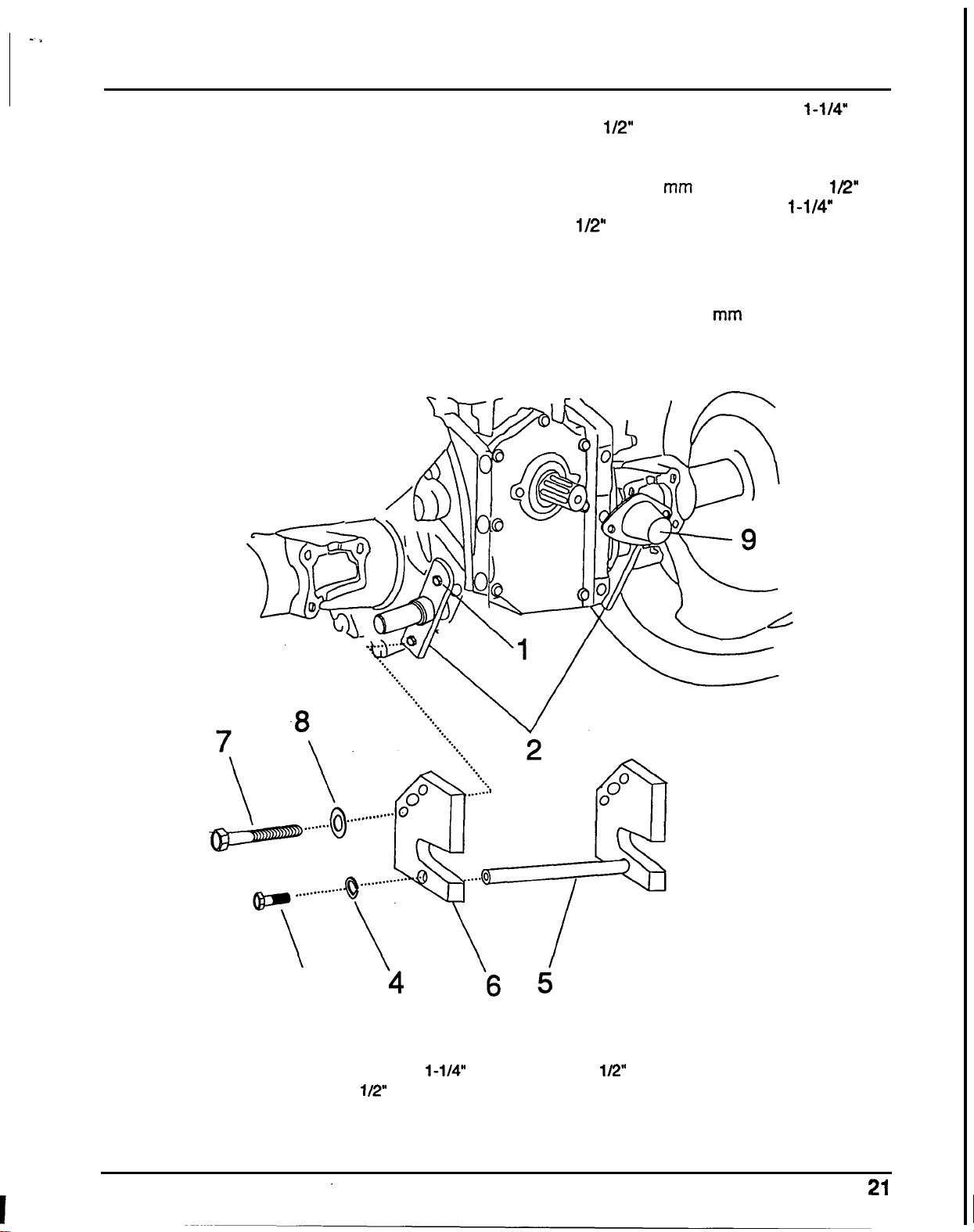
ASSEMBLY
INSTRUCTIONS
4.
Remove and retain the four
12
x
75
mm flange
5.
Remove one of the
two
1/2
NC
x
1-1/4"
bolts
bolts
(1)
holding the
left
and right rolling pins
(2)
(3) and
1/2"
lock washer
(4)
holding the cross
to the transmission (Figure
9).
The
12
x
75
mm
shaft
(5)
to the
two
set plates
(6).
Install the set
bolts and rolling pins must be retained for
plates in place of the rolling pins
as
shown with
3
-
point hitch installation.
the four
12
x
80
mm bolts
(7)
and four
1/2"
flat
washers
(8).
Install the
1/2
NC
x
1-1/4"
bolt
(3)
and
1/2"
lock washer
(4)
removed from the set
plate and tighten to the specified torque.
Tighten the
12
x
80
mm bolts (7) to the specified
torque.
6.
Remove the
two
6
x
12
mm
flange bolts and the
rear PTO cover
(9).
\
3
'4
1.12
x
75
mm
bolt
6.
Set plate
(R)
2.
Rear
Rolling Pin
(R)
7.12
x
80
mm
Bolt
4. 112"
Lock
washer
9.
PTO
cover
5.
Cross
shaft
3.
1/2 NC
X
1-1/4"
bolt
GR
5
8.
1/2"
Flat
washer
Figure
9.
Set
Plate
Assembly
Installation
*
-
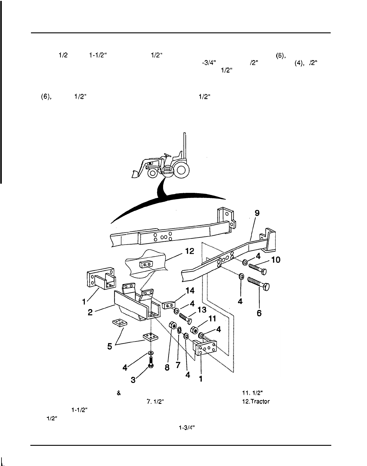
ASSEMBLY
INSTRUCTIONS
7.
Loosely install the left and right crossmember
brackets (1) to the crossmember (2) using the
eight
112 NC
x
1-1/2" bolts
(3)
and 1/2" flat
washers (4). Set the
two
4
-
hole crossmember
set plates
(5)
against the crossmember as
shown (Figure 10).
8.
Remove
and
retain the four 1/2 NC
x
2
"
bolts
(6),
eight 1/2" flat washers (4); four lock
washers (7) and four nuts
(8)
from front end
loader sub
-
frame. This hardware will be
reinstalled in the same location in step 9.
9. Loosely bolt the crossmember brackets to the
front end loader sub
-
frame assembly
(9)
using
the four 1/2 NC
x
2
"
bolts
(6),
eight 1/2 NC
x
1 -3/4" bolts (1
0),
1 /2" flat washers (4), 1 /2" nuts
(8)
and 1/2" lock nuts
(1
1) as shown.
10. Install the crossmember to the tractor's frame
(12) using the four 12
x
35
mm bolts (13) and
1/2" flat washers
(4).
Install a 2
-
hole set plate
(14)
on each side against the crossmember.
Tighten all hardware to the specified torque.
1. Bracket,
cross
member (L
&
R)
6.
1/2 NC
x
2 Bolt
GR
5
11.1/2" NC
Lock
nut
2. Crossmember
7.1/2" Lock washer 12.Tractor frame
mounting
holes
4.
1/2" Fiat washer
9.
Front end loader sub
-
frame
14.
2
-
Hole set plate
5.
4
-
Hole
set
plate
10. 1/2 NC
X
1-314" Bolt
GR
5
3. 1/2 NC
X
1-1/2"
Bolt
GR
5
8.
1/2 NC Nut 13.12
x
35
mm
Bolt
Figure
10.
Crossmember installation
22
..
ASSEMBLY
INSTRUCTIONS
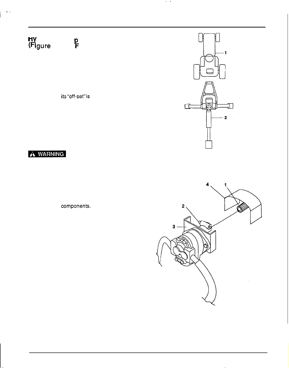
H
draulic Pum Installation
#
lgure
11
and
F
igure
12)
1. Check all hydraulic fittings and lines to
be
sure
they are tight and free of kinks and twists.
2.
Back the tractor as near as possible and center
on backhoe. See Figure 12.
3.
The pump mounting bracket
(3)
is designed to
slip inside tractor’s PTO shield
(4).
Install the
bracket
so
its“off-set”is towards the tractor and
PTO.
4.
Grease the drive line sliding surfaces and slide
the female tube of the pump mounting coupler
over the male PTO shaft. See Figure 11.
5.
Check that the hydraulic pump spring activated
locking pin (2) slides freely and is seated firmly
in the tractor PTO shaft spline groove.
1-
The PTO turns at
540
RPM.
If
the coupler is not locked to the PTO shaft at
the tractor end, the pump assembly can fly
loose with great force, and
is
capable
of
causing serious injury
6.
Before installing the sub
-
frame to the tractor, it
may be necessary to reposition the hydraulic
hoses to remove kinks, bends or hose rubbing
on frame
components. Loosen the hydraulic
fittings at the pump or
oil
filter assembly and
hose connections.
Do
this quickly to minimize
hydraulic fluid leakage. Adjust the hydraulic
hose to obtain
a
suitable direction. Tighten all
hydraulic fittings and hose connections.
csr
1.
Tractor
2.
Backhoe
Figure
11.
Tractor
-
Backhoe
Alignment
4.
1
1.
PTO
2.
PTO
locking pin
3.
Pump mounting bracket
4.
PTO
shield
Figure
12.
Pump Installation
23
Attaching Backhoe
To
Tractor
The backhoe hydraulicsystem will be used
to
make
mounting on tractor easier.
It
is necessary this be
done with tractor engine running at
idle.
Am
The operator or service
person must be competent and use extreme
care during
this operation
to
prevent
equipment damage and personal Injury.
Always stand on the tractor side or
reannrard
of
backhoe to avoid the posslbliity
of
being
trapped should
the
boom swing control be
accidentally activated.
1.
Be sure backhoe controls are in centered and
neutral position.
2.
With the backhoe hydraulic pump securely
mounted, and tractor PTO and transmission in
neutral, start tractor engine idling. Engage PTO
verycarefully and allow pump to start smoothly.
Refer to the
H6522 Owner’s Manual for rear
PTO engagement.
Very little engine power 1s
requ re
o
power hydraulic system In this
mode. Should engine pull down excessively,
check plumbing hook
-
up for reversed lines or
a control lever stuck
in
an operating position.
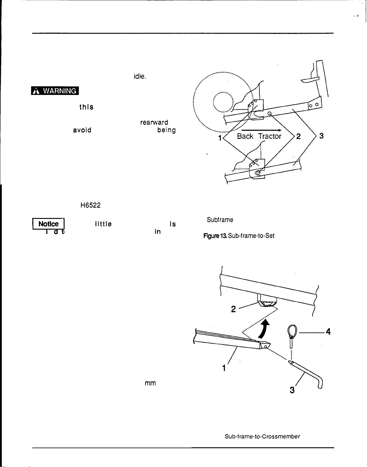
3.
Raise
backhoe
with
stabilizer controls to
align
grooves in the right and left set plates (1) with
the cross shaft
(2)
of the sub
-
frame assembly.
Level backhoe from side to side with stabilizer
controls. See Figure
13.
4. Use the right control lever and position the
backhoe
so
that the sub
-
frame
is
lowest at the
crossmember end.
5.
Position the backhoe
so
that the sub
-
frame,
cross shaft locks completely into the grooves
of the right and left plate assemblies.
.
6.
Use the right control lever to bring the
crossmember end of the sub
-
frame into the
crossmember. Lock the sub
-
frame (1) into the
crossmember
(2)
with
the
19
x
397
mm
pin (3)
and Klik pin (4). See figure 14.
7.
Turn the upper link
(1)
threaded end until the
hole aligns with the center hole of the top link
bracket
(2).
Install the top link pin
(3)
and the
Klik pin (4). See Figure
15.
24
ASSEMBLY INSTRUCTIONS
1.
Set
plate
2.
Subframe cross shaft
3.
Bachoe sub
-
frame
Fyute13.
Sub-frame-to-Set Plate Installation
1.
Sub
-
frame end
3.
Pin
2.
Crossrnernber
assembly
4.
Klik
pin
Figure
14.
Sub-frame-to-Crossrnember
Installation

ASSEMBLY
INSTRUCTIONS
8.
Check that the main console is perpendicular
9.
ENGAGE PTO AND
RUN
AT IDLE FOR
5
MINUTES, THEN CHECK OIL LEVEL. Add
with the tractor on a flat surface.
fluid as necessary.
10.
Operate all functions through full cylinder
stroke to purge air from system. CHECK OIL
LEVEL again and add. fluid as necessary.
Seat Installation and Adjustment
(Figure
16)
1.
Install seat and upper seat support.
2.
The seat may be adjusted fore, aft, up and
down for operator comfort.
It
is necessary to
use the
two
adjustments together. Moving the
seat down also moves
it
forward, moving it up
also moves it rearward. The fore and aft
adjustment may
be
used with the up and down
adjustment to obtain desired position. Never
operate the backhoe unless the sub
-
frame has
been installed, adjusted and operator's area
(shown shaded in Figure
16)
is
free
from
obstructions in a
40
"
radius from the seat to a
point
10
"
behind the seat back.
3.
Seat adjustment may be used to obtain
adequate head clearance.
1.
Top link assembly 3. Top link pin,3/4
X
3-1/4"
2.
Top link bracket
(tractor)
4.
Klik
pin
High Strength
Figure
15. Top Link
-
to
-
Tractor Installation
MINIMUM
RADIUS
1.
Seat
assembly
2.
Seat
adjusting
holes
3.
Seat
clevis
pin and
Klik
pin
Figure
16.
Seat Installation

1
,-
I
OPERATION
OPERATION
Safety is
a
primary concern in the design and
manufacture of
our
products. Unfortunately, our
efforts to provide safe equipment can be erased by
a single careless act of an operator.
In addition to the design and configuration
of
equipment, hazard control and accident prevention
are dependent upon the awareness, concern,
prudence and proper training of personnel involved
in
the operation, transport, maintenance and
storage of equipment.
The best safety device is an informed, careful
operator. We ask you to be that kind of an operator.
Operating the backhoe
without adequate operator clearance may
cause the backhoe boom to pin the operator
agalnst the tractor causing serious Injury.
(Refer to Danger Label on page
8.)
The safe operation of this machine is the
responsibility of the
operator.The operator should
be familiar with the backhoe, tractor and all safety
practices before starting operation. Read the
Safety Rules on page
9
and
10.
Before working on backhoe, extend boom and
dipperstickand place bucket on ground. Make sure
that all system pressure has been relieved by
operating controls before maintenance, service
or
disconnecting any hydraulic lines.
I'
Hydraulic system leak down
and failure of mechanical or hydraulic system
can cause equipment to drop causing serious
injury.
PRE
-
OPERATION
CHECK
LIST
0
Check that backhoe and sub
-
frame are
properly and securely attached to tractor and
front end loader sub
-
frame.
!
DA
operating the backhoe
without the sub
-
frame Installed will make the
backhoe unstable which will cause serious
injury or death to the operator.
0
Check for hydraulic leaks. Use paper
or
cardboard, not body parts to check for leaks.
Make sure all hydraulic connections are tight
and all hydraulic lines and hoses are in good
condition before engaging tractor PTO.
I'
Hydraulic fluid (oil) under
pressure will penetrate skin causing serious
injury. Keep hands and body away from
pressurized lines.
Make sure that all operating and service
personnel know that in
the
event hydraulic fluid
penetrates skin, it must be surgically removed
within a few hours by a doctor familiar with
this
form
of injury, or gangrene may result.
0
During inspection, check that all nuts and bolts
are secure and clevis pins are properly cotter
pinned.
Be sure special heavy
-
duty top link, provided
with backhoe, is installed.
0
Make sure only original equipment
high
-
strength top link pin, provided with tractor,
is used to attach top link to tractor.
0
Use the high
-
strength pin provided with the
backhoe to mount the top link to the tractor
bracket.
0
Place all backhoe controls in neutral position
before starting tractor engine.
0
Check hydraulic reservoir level.
Remove transport lock bar from the boom.
Push transport lock bar down fully to prevent
damage.
0
Pull swing lock pin up and secure in storage
position with safety pin.
0
The front
-
end loader must be installed to
provide proper counterweight and
for
backhoe
operation.
!
DA
Using the backhoe with
improper counterweight will cause the tractor
to tip over causing Injury or death. Read the
safety information on page
9
and
10
before
beginning.
OPERATION
Starting and Stopping
A
tractor
-
driven PTO pump supplies hydraulic
pressure for backhoe operation. Instructions for
engaging and disengaging the PTO are in the
H6522 Owner’s Manual. Learn how to disengage
PTO quickly should an emergency occur.
Operate tractor
PTO
at
540
rpm.
Operating the pump in excess of
540
rpm
will
cause overheating and equipment damage.
Commencing Operation
1.
Consult local utilities before digging. Know
location of and avoid contacting all
underground cables, pipelines, overhead wires
and other hazards In digging area.
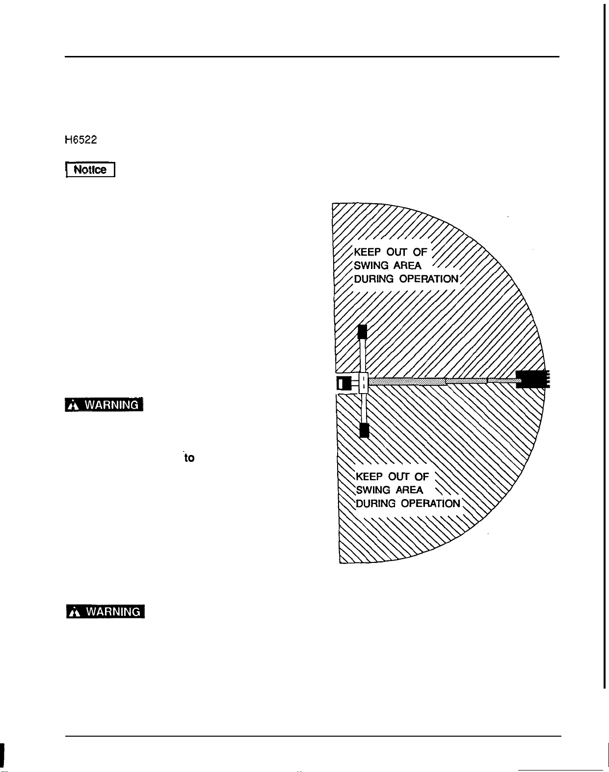
2.
Keep bystanders away from operator,
stabilizer and maximum bucket swing areas
(see Figure
17).
3.
Place and keep 3
-
point lift quadrant lever in
lowered position at all times.
4.
Do
not use backhoe for craning; It is designed
for digging.
Do
not use the backhoe for
craning. Using the backhoe for craning can
cause serious injury in the event of a
mechanical failure or hydraulic leak which
would cause the load
.to drop on the person
within the
“SWING
AREA”
(see Figure
17).
5.
Do
not dig with backhoe unless stabilizers are
down and on a firm surface. Stay clear of steep
areas
or
excavation banks that are
soft
or
could
give away.
6.
Do
not allow children or unqualified persons to
operate equipment.
7.
When operating controls, always sit in the
backhoe seat.
1-
Operating the backhoe
without adequate operator clearance may
cause the backhoe boom to pin the operator
against
the
tractor causing serious injury.
(Refer to Safety Label on page
8).
Figure
17.
Backhoe
Swing
Area
27
..
OPERATION
Positioning the Machine
1.
2.
3.
4.
Before operating in a unfamiliar area, walk
around the full length of the proposed site and
check for hidden holes,. drop
-
offs
or
obstacles
that could cause an accident.
Lower stabilizers until they carry the weight of
the backhoe. Place the front end loader bucket
flat on the ground. Lower the loader’s
lift
arms
until weight is removed from front tractor tires.
Level the machine using stabilizers and front
loader before starting to dig.
Stability is very important when operating
backhoe in the extreme swing positions as this
causes weight transfer.
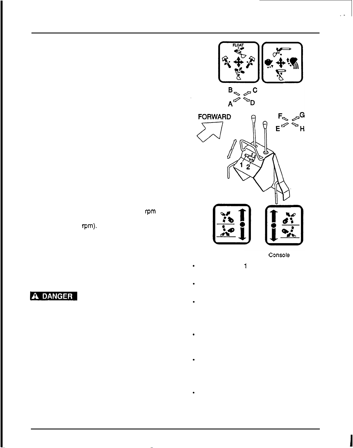
Control Handle Operation
(Figure
18)
1.
Assume your position in the operator’s seat.
2.
When engaging PTO, engine rpm should
always be low. Once engaged, engine
rpm may
be increased to desirable operation speed (not
to exceed
540
rpm).
3.
When becoming familiarwith backhoe controls,
start with
a
lower rpm.
4.
Before operating, perform a functional test by
placing control handles in their various
positions and making certain correct operation
occurs, matching labels on operator’s console.
Pay specific attention to float position of boom.
!
DA
Do
not operate the backhoe
if
functions differ from label; serious injury or
death could occur.
5.
It is not difficult to become a successful
operator. Control lever operating labels (shown
in Figure
18)
are next to the operating control
levers. Study these labels; they will assist you
in becoming familiar with the controls.
Figure
18.
Operator’s
Console
Pulling handle
1
up will raise left
stabilizer; pushing down lowers it.
Pulling handle
2
up will raise right
stabilizer; pushing down lowers it.
Pulling left control handle back (toward
A) raises boom; pushing it forward
(toward C) lowers it. Full forward (toward
C) is the float position.
Moving left control handle left (toward
B)
swings boom left; moving it right (toward
D)
swings boom right.
Pulling right control handle back (toward
E)
moves dipperstick down and toward
operator; pushing it forward (toward
G)
moves it
up
and away
from
operator.
Pushing right control handle left (toward
F) curls bucket toward operator; pushing
it right (toward
H)
extends bucket out
away from operator.
28
OPERATION
6.
7.
8.
9.
Operate control levers, swinging boom several
times to practice control.
Do
not operate swing
more than
45'
each way the first few times.
Gradually increase arc.
After becoming familiar with the backhoe
operation, practice coordinated use of the
controls in a safe open area at reduced engine
speed. Gradually increase engine speed as the
technique is mastered.
Operate backhoe gently and smoothly. Avoid
swinging boom into mainframe. Sudden
stopping
or
jerking could result in serious
damage to tractor and backhoe.
Strive to develop a smooth digging cycle. Avoid
abrupt
or
jerky movements. This is
accomplished by operating two
or
more
controls at the same time and not allowing the
cylinders to reach the limit
of
travel.
10.
Should
you
become confused
or
lose your
control orientation during operation, simplyturn
loose of the controls and reorient yourself.
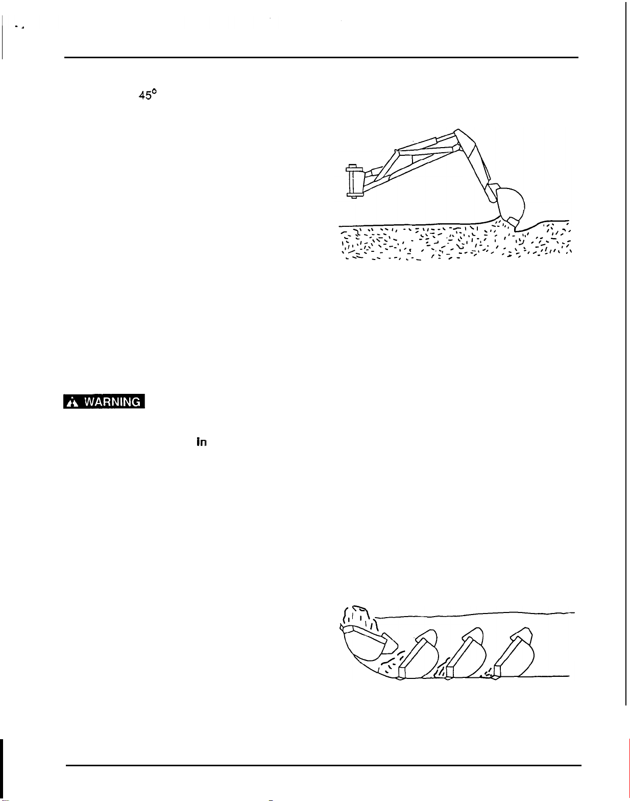
Starting the Excavation (Figure
19)
Consult local utilities before
digging.
Know location
of
and avoid contacting
all underground cables, pipelines, overhead
wires and other hazards
In
digging
area.
1.
To start the excavation, position backhoe as
shown for maximum breakout force.
2.
Actuate the dipperstickcylinder to start digging.
Approximately halfway through digging cycle,
start bucket curl while continuing crowding
dipperstick
in.
Should bucket stall, raise boom
slightly.
3.
Do
not use down pressure on the boom when
starting to dig,
as
this will
lift
machine and move
it out of alignment with the work.
Filling the Bucket (Figure
20)
1.
Control bucket attitude throughout digging
cycle to keep teeth parallel to bottom
of
excavation. This will provide best penetration
angle and minimize dragging and scraping
bucket through the ground.
2.
Penetration depth is determined by soil
condition and type.
3.
4.
5.
Figure
19.
Starting Excavation
Only use dipperstick and bucket during the
digging cycle. As the dipperstick moves the
bucket through the soil, curl bucket to maintain
proper bucket position.
At the end of the pass,
or
when bucket is full,
curl bucket completely, lift bucket from
excavation and swing boom to dump site at
least
two
feet away from opening.
To obtain a cleaner trench and avoid material
buildup directly in front of backhoe, extend
dipperstick and curl bucket completely while
starting to lift it out
of
the excavation. This will
allow excess material to fall back into the
excavation.
Figure
20.
Filling
Bucket
29
’-
I
OPERATION
Dump
and Return Cycle
Keep the swing
-
dump
-
return cycle as brief as
possible. Keep dipperstick moving outward and
start boom swing as soon as the bucket clears the
excavation. Continue extending dipperstickand, as
you approach the spoil pile, start
to
dump bucket.
When bucket is empty, dipperstick and bucket are
in position to resume digging upon return to the
excavation.
Trenching and Excavating
Procedures
(Figure
21)
Trenching is the most basic backhoe digging
operation. Other operations are variations of this
basic function.
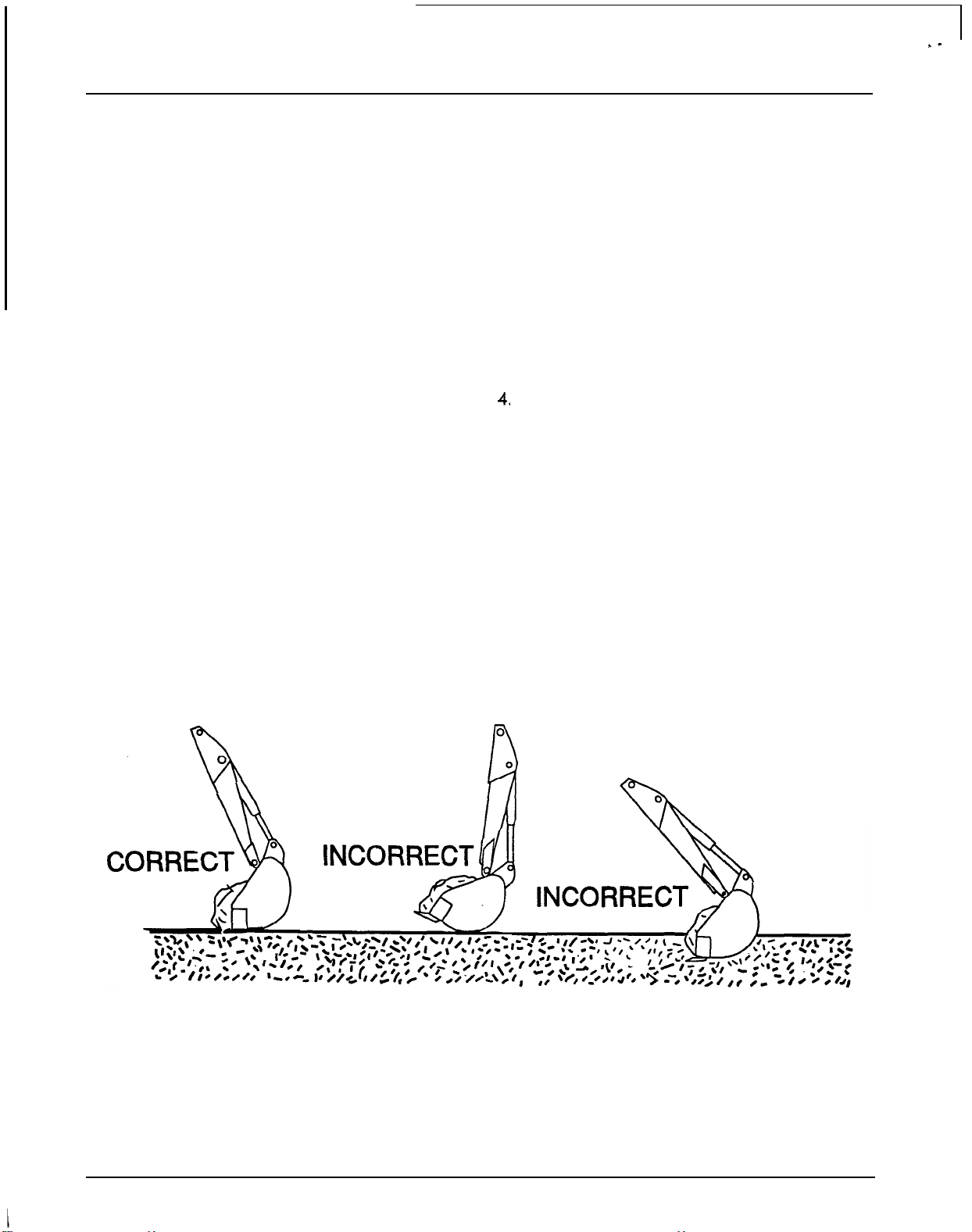
1.
2.
3.
4,
To
maintain a level trench bottom, set bucket
at proper approach angle and while crowding
dipperstick in, continually move bucket curl
lever to maintain correct cutting angle. At the
same time, place boom control in the full
forward (float) position and keep the bucket in
the same plane.
When handle
is
placed in the float position,
pressure on both sides of boom cylinder is
released.
Digging near center of swing
so
material may
be dumped on either side will produce good
results. Never dig near stabilizers.
Continue the trench by moving machine along
trench centerline away from existing
excavation. Move machine approximately
one
-
half the effective backhoe reach. Moving
too far will require excessive down pressure for
digging and hand clean
-
up
of
trench bottom.
Figure
21.
Trenching
30
OPERATION
Side
Slo
e
Trenching
or
Excavating
(Figure
B
2)
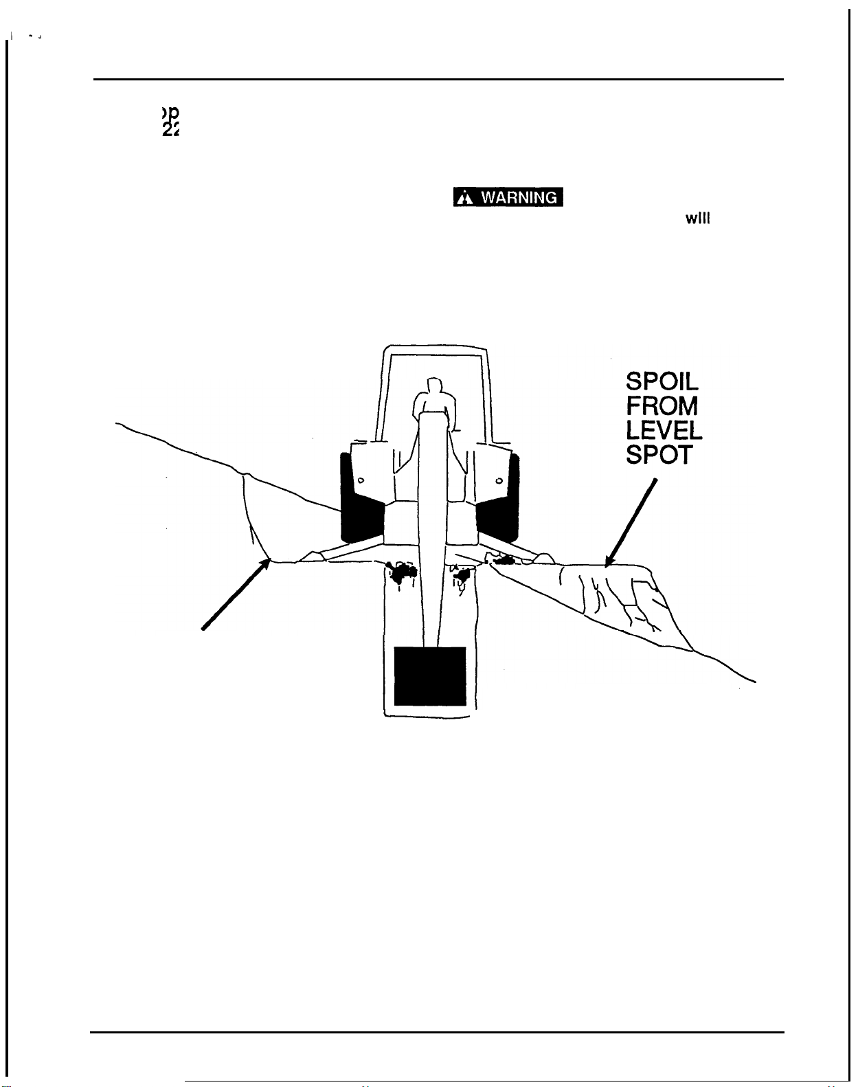
1.
When operating on a side slope, the backhoe
must be positioned using the method shown in
Figure
22.
2.
Cut a level spot
for
the uphill side
of
the
machine and place the spoil from the levei spot
on the downhill side.
3.
Be careful when swinging loaded bucket on a
hillside. When operating on a side slope,
always place the trench spoil on the “UPHILL”
side of backhoe to minimize the possibility of
upsetting the tractor.
1-
Dumping
the
spoil
on
the
“DOWNHILL”
side
of
the tractor
wlll
cause
the
tractor to upset causing serious
injury.
Dump
the spoil on the
“UPHILL”
side.
UPHILL
CUT
LEVEL
SPOT
c
J
Figure
22.
Cutting
a
Level
Slot
for
Uphill Side
DOWNHILL
31
'
-
OPERATION
Transporting
1.
Engage the swing and boom transport locks
and attach Slow Moving Vehicle (SMV) sign
before transporting backhoe. When
transporting, you must wear a seat belt
if
your
tractor has
ROPS
installed.
2.
Lower the bucket to the ground, shut the engine
OFFand remove the ignition key before leaving
the equipment unattended. Never leave
equipment unattended with engine running or
with bucket in raised position.
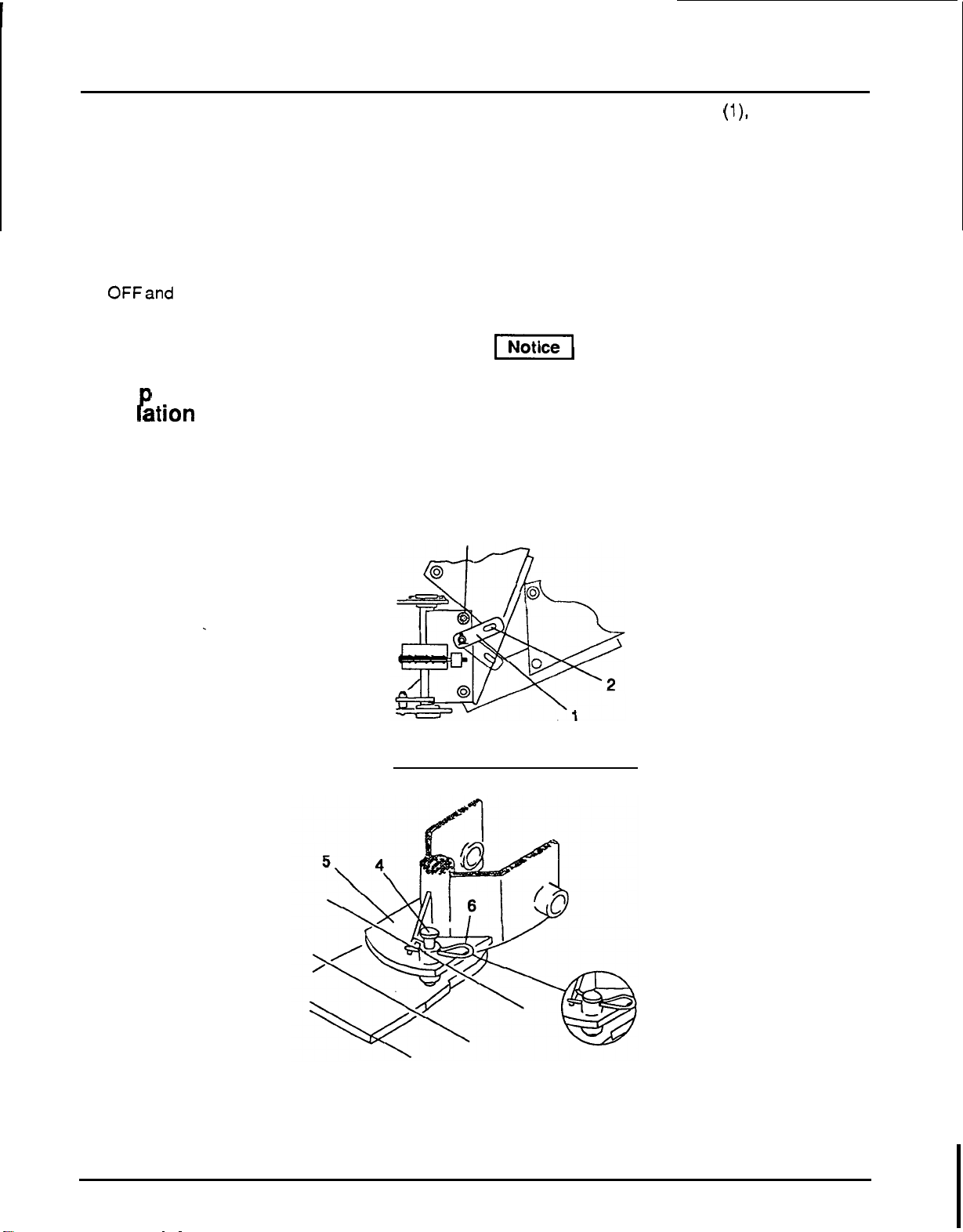
Trans ort and Swing
Lock
Instal
P
ation
(Figure
23)
1.
Engage transport lock by fully retracting boom
and dipperstick.
3
2.
Position transport lock bar
(l),
located on right
side of swing frame, over transport lock pin
(2).
3.
Center boom from side to side and install swing
lock pin
(4)
through kingpost plate
(5)
and
boom. Secure swing lock pin
(4)
with a safety
pin
(6)
as shown.
4.
Always raise stabilizers before transporting
backhoe.
5.
Before operating backhoe, disengage
transport lock bar and store swing lock pin.
-1
Operating the backhoe with the
lock bar installed can damage the equipment.
1.
Transport
lock
bar
4.
Swing
lock
pin
2.
Transport
lock
pin
5.
Kingpost plate
3.
Bumper pad
6. Safety
pin
Figure
23.
Transport
&
Swing
Lock
Installation
32
OPERATION
Removing and Storing Backhoe
Keep all persons away from
operator control area while removing or
Installing backhoe or performing adjustments,
service or maintenance.
1.
The hydraulic system will be used
to
remove
the backhoe. It is necessary this be done with
tractor engine running at Idle. The operator
or
serviceman must be competent and use
extreme care during this operation. Always
stand on the tractor side
or
rearward of
backhoe.
1-
The boom swing control can
be activated by accident trapping you and
causing severe Injury. Stand to the side when
removing the backhoe to prevent equipment
damage and personal injury.
2.
Remove seat and upper support assembly
before installing
or
removing backhoe from
tractor.
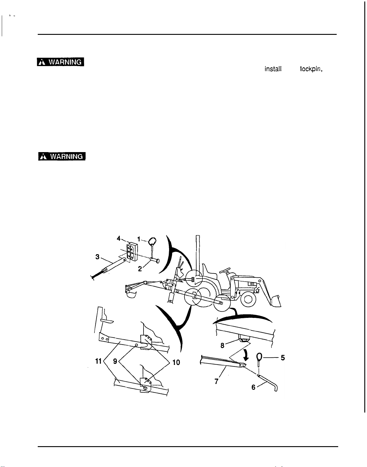
Sub
-
frame Mounting Removal
(Figure
24)
1.
2.
3.
4.
n
Center the boom and install swing lockpin, then
extend boom and dipperstick. Rest bucket on
the ground. Lower the stabilizers to take
backhoe weight
off
of
the tractor. Remove pin
that attaches the top link to the tractor.
Remove the pin that secures the sub
-
frame to
the crossmember. Raise the rear of the
backhoe with stabilizers to pivot the front of the
sub
-
frame down.
Roll
the tractor forward to
dislodge the sub
-
frame’s cross shaft
from
the
set plate assembly.
Place blocks under the main frame and raise
the stabilizers to lower the backhoe mainframe
onto the blocks. Block the backhoe as
necessary
to
make it stable. Lower the backhoe
to
a
stable position relieving all hydraulic
pressure.
Disengage the PTO, stop tractor engine and
remove key. Remove pump from the PTO and
secure it to the backhoe.
1.
klik pin
2.
clevis pin
3. Upper link
4.
Upper
link
bracket
5.
Klik
pin
9.
Sub
-
frame cross
shaft
6.
Pin
10.
Set
plate
7.
Sub
-
frame
11.
Sub
-
frame
8.
Crossmember
Figure
24
Removing Backhoe
33

TROUBLESHOOTING
TROUBLESHOOTING
PROBLEM POSSIBLE CAUSE SOLUTION
1.
Noisy pump caused by a. Oil too heavy a. Change to proper viscosity.
cavitation
b. Oil filter plugged
b. Replace filter.
c. Suction line plugged or too c. Clean line and check for size.
small
2.
Oil heating a. Oil supply low a. Fill reservoir.
b. Contaminated oil
b.
Drain reservoir, change filter
and refill with clean oil.
c. Setting of relief valve too high c. Set
to
correct pressure.
d. Oil in system too light
d.
Drain reservoir and refill with
or too low
proper viscosity oil.
e. Pump operating too fast e. Do not exceed
540
rpm PTO
speed.
3.
Shaft seal leakage a. Worn shaft seal a. Replace shaft seal.
b. Broken diaphragm seal or
b,
c
&
d.
If
replacing the shaft
back
-
up gasket seal does not stop leakage,
the pump should be
disassembled and checked
for items b, c
&
d.
c.
Bearings out of position
d.
Excessive internal wear
4.
Foaming oil a.
Low
oil level a. Fill reservoir.
b.
Air leaking into.suction line
b.
Tighten fittings.
c. Wrong kind of oil
c. Drain and
fill
reservoir with
non
-
foaming oil.
d.
Moisture in oil
d.
Kee oil temperature below
180
F and continue to
operate as
oil
dries out, or
replace
oil
and purge system
if
foaming is excessive.
5.
Boom drops as dipperstick or a. Check valve leaking
a
Clean or replace check valve
E
bucket cylinder lever is assembly.
activated while boom control
is in raised position
34
I
=-,
SERVICE
&
MAINTENANCE INSTRUCTIONS
SERVICE
&
MAINTENANCE INSTRUCTIONS
Keep hands and body away from pressurized lines.
Use paper
or
cardboard, not body parts to check
for leaks.
4-
Hydraulic fluid (oil) under
pressure will penetrate skin causing serious
injury.
Make sure that all operating and service
personnel
knowthat In the event hydraulic fluid
penetrates skin, it must be surgically removed
within a few hours by a doctor familiar with this
form of injury, or gangrene may result.
Make sure that all operating and service personnel
know that in the event hydraulic fluid penetrates
skin, it must be surgically removed within a few
hours by a doctor familiar with this form of injury,
or
gangrene may result.
Always wear relatively tight and belted clothing to
avoid entanglement in moving parts. Wear sturdy,
rough
-
soled work shoes and protective equipment
for eyes, hands, hearing and head.
Before working on backhoe, extend boom and
dipperstickand place bucket on ground. Make sure
that all system pressure has been relieved by
operating controls before maintenance, service
or
disconnecting any hydraulic lines.
m
Hydraulic system leak down
and failure
of
mechanical or hydraulic system
can cause equipment to drop causing injury.
Make sure all hydraulic pressure is relieved off
of the backhoe before performing service on
the equipment.
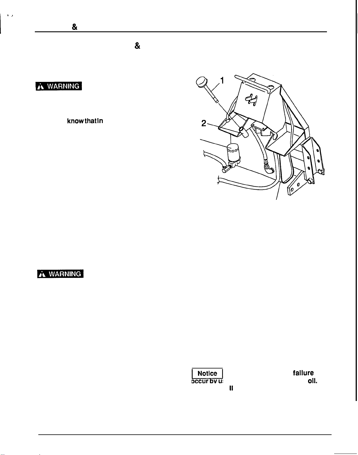
Hydraulic System (Figure
25)
A-
Daily, check the fluid level in reservoir with filler cap
dipstick. Contamination will shorten the
life
of
hydraulicsystem components. Change oil and filter
after first
20
hours of operation and then every
200
hours of operation
or
annually, whichever occurs
first.
In
extremely dusty
or
dry conditions, more
frequent changes may be necessary. System
capacity
is
approximately
5
to
5
-
1/2
U.S.
gallons.
1.
Operate tractor PTO at
540
rpm until the
system reaches operating temperature.
3
4
1.
Oil
breather cap
3.
Oil
filter
2.
Oil
filler
neck
4.
Oil drain
plug
Figure
25.
Oil Maintenance
2.
Remove the drain plug
(4)
from the hydraulic
oil
reservoir.
3.
Drain the oil into a suitable container and
dispose of properly.
Note: Please dispose of used hydraulic
oil
in a
manner that is compatible with the environment.
Do not throw it in the trash
or
pour it on the ground.
4.
Put the oil pan under the oil filter
(3).
Remove
the hydraulic oil filter.
5.
Clean the oil filter mounting base. Lightly
lubricate the new filter O
-
ring and install the
filter onto the base.
6.
Fill
with clean oil.
Do
not mix oil types orgrades.
rn
Hydraulic system fallure may
occur y using an unsuitable hydraulic
oil.
Use
only Dexron
II
type
ATF.
7.
ENGAGE PTO AND RUN AT IDLE
FOR
5
MINUTES, THEN CHECK
OIL
LEVEL. Add
fluid as necessary.
35
-
,
SERVICE
&
MAINTENANCE INSTRUCTIONS
Relief Valve
This valve
is
preset at the factory to prevent system
pressure exceeding
2000
psi.
Do
not attempt to
reset the valve.
If
it is malfunctioning, replace
it
with
an authorized factory replacement part.
Swing Chain Adjustment (Figure
27)
1.
Center boom to mainframe. Loosen locknuts
on chain adjustment bolts and tighten nuts on
adjustment rods until all slack
is
removed from
chains.
-1
Do
not over
-
tighten the chain.
Over
-
tightening will cause excessive load and
premature failure.
2.
Tighten locknuts on chain adjustment bolts.
Kingpost and Swin Cylinder Bolt
Inspection (Figure
9
7)
Kingpost and swing cylinder bolts were installed
using Loctite and should not loosen. However, they
should be checked daily to be sure they are tight.
Should any loosen, or when replacing them during
a repair operation, clean bolts and nuts, apply
Locquicprimer and Loctite
609.
Tighten as outlined
in torque chart on page
1
1.
1.
Replacement
tooth
2.
Tooth
shank
Figure
26.
Tooth Replacement
Bucket Tooth Replacement
(Figure
26)
1.
Remove worn tooth by driving a chisel between
2.
Install replacement tooth and use
a
punch to
shank and tooth.
peen tooth to shank on both sides.
1.
Kingpost 3. Mainframe
2.
Swing cylinder
4.
Chain adjustment
Figure
27.
Chain Tightening
&
Bolt
Torque
36

SERVICE
&
MAINTENANCE INSTRUCTIONS
Hydraulic Hoses and Fittings
1.
Hydraulic hoses are severely worked on a
backhoe. Examine them daily and replace
if
necessary. Hose routing is very important.
Make certain hoses can move freely, without
kinking, and cannot be damaged or cut by
backhoe action.
2.
When tightening hoses and fittings, always use
two wrenches: one to hold hose and one to
tighten the fitting. This will prevent hose from
twisting and kinking.
3.
Always back locknut
off
and screw fitting all the
way in for fittings that must be positioned and
that use O
-
rings for sealing. Then hold in
position and tighten locknut. Fittings with
O
-
rings and flange do not require additional
sealant, replace damaged O
-
rings.
-1
Teflon tape should be used to
seal pipe threads. Use care when applying
Teflon Tape to prevent It from entering the
hydraulic system.
Notes
C
37
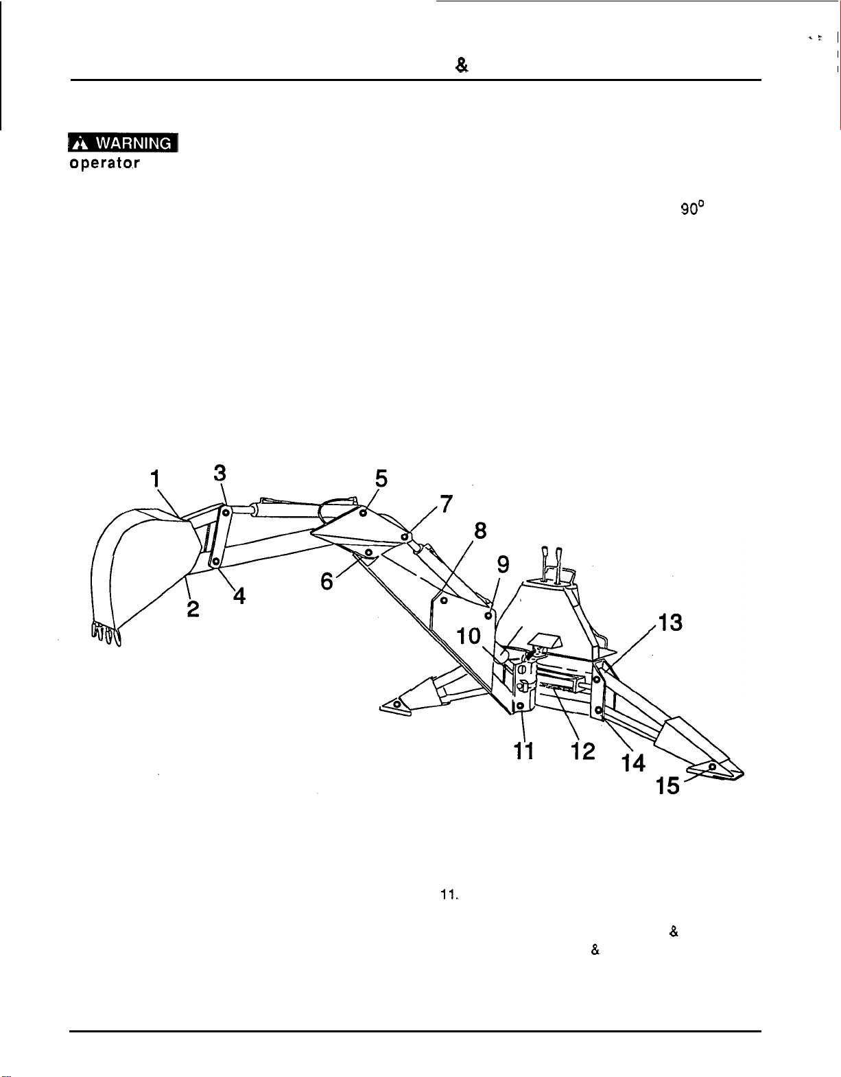
ct
1
I
SERVICE
&
MAINTENANCE INSTRUCTIONS
I
Lubrication (Figure
28)
Keep
all
persons away from
0perato.r control area while performing
adjustments, service
or
.maintenance.
1.
Do
not let excess grease collect on or around
parts, particularly when operating in sandy
areas. The accompanying illustration shows
lubrication points for the backhoe.
2.
It is recommended that all fittings be lubricated
daily
or
every eight hours of operation. In very
wet
or
dry
conditions, lubricate every four hours
of operation.
3.
4.
Use an
SAE
multi
-
purpose type grease for all
locations shown unless otherwise specified. Be
sure to clean fitting thoroughly before using
grease gun. One good pump of most guns is
sufficient.
Position backhoe for easy lubrication by
placing boom and dipperstick at
90'
to each
other with bucket cutting edge vertical and
teeth resting on ground. Raise stabilizers to
lubricate rod end of cylinders.
1.
Bucket pivot
2.
Bucket pivot
3.
Bucket cylinder rod end
4.4
-
Bar pivot
5.
Bucket cylinder base end
6.
Dipperstick pivot
7.
Dipperstick cylinder rod end
8.
Boom cylinder base end
9.
Dipperstick cylinder base end
10.
Boom cylinder rod end
11.
Boom pivot
12.
Swing chain
(20W
motor
oil)
13. Stabilizer cylinder base end (right
&
left)
14.
Stabilizer pivot (right
&
left)
15. Stabilizer cylinder rod end (right
&
left)
16.
Swing frame pivot (top
&
bottom)
Figure
28.
Lubrication
Points
38

SERVICE
&
MAINTENANCE INSTRUCTIONS
HYDRAULIC CYLINDER REPAIR
General Hydraulic Repair
Information
A
clean working area is necessary for any hydraulic
repair. Repairing hydraulic components in
a
dirty
area is
a
waste of time.
All
parts must be carefully cleaned before
reassembly. We recommend that when repairing
hydraulic components, you always replace existing
seals with new ones. Clean
all
components in
solvent and blow dry with low pressure air.
Threaded Collar Type Cylinder
Repair (Figure
29)
Cylinders are obtained from
two
suppliers. It
Is
Important that you properly identify the
manufacturer of the cylinder you are repairing.
Cylinders have either an “E” or
“L”
stamped in the
barrel near the butt end.
Make proper manufacturer identification, then refer
to the
“E”
or
“L”
column when ordering parts.
Disassembly
1.
Loosen set screw and unscrew threaded collar
(2)
from barrel (9). Pull on rod
(4)
to remove
piston from barrel.
2.
Clamp cross
pin
end of rod assembly
(4)
in a
vise with protective jaws. Remove locknut
(6)
from
rod assembly. Remove piston
(7)
and
gland
(8)
from rod.
3.
Remove
and
discard
all
seals, wear rings and
O
-
rings.
4.
Clean
all
components in solvent and blow
dry
with low pressure air.
1
Assembly
i
1.
Lubricate O
-
rings
and
seals with clean
hydraulic fluid. Install back
-
up washer (3H) on
gland
(8),
then install O
-
ring (3E)
in
exterior
O
-
ring groove of gland. Install rod seal (3F) into
inner groove of gland with open portion of
V
-
groove toward piston.
1
,,5
IDENTIFICATION
STAMP
1.
2
x
16-3”’
Hydraulic cylinder
2.
Collar
3.
Seal
k‘it
(contains
3A
through
3H)
3A.
Rod
static seal
38. Wear ring
3C. O
-
Ring
3D.
Piston seal
3E.
Gland static seal
3F. Rod seal
3G.Rod wiper
3H.
Back
-
up washer
4.
Rod assembly
5.
Grease zerk
6.
7/8“ Self
-
lock
hex
nut
7. Piston
8. Gland
9.
Barrel assembly
Not
used
in
cylinder stamped
“L”
Figure
29.
Hydraulic Cylinder
(Threaded Collar
Style)
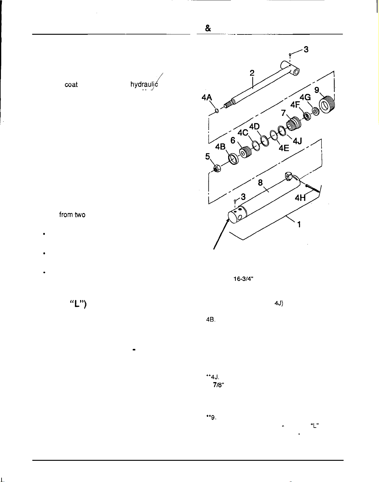
SERVICE
81
MAINTENANCE INSTRUCTIONS
2.
Place rod wiper
(3G)
in outer gland groove.
Slide gland assembly
(8)
onto rod. Place wear
ring
(3B)
in wide groove of piston. Place O
-
ring
(3C) and piston seal (3D) in narrow piston
groove.
3.
Lightly coat rod threads with hydrauvc oil and
slide O
-
ring (3A) over threads and into groove.
Install piston
(7)
onto rod
(4)
with wear ring on
side away from gland. Install locknut
(6)
and
torque
to
175
ft
-
lbs.
4.
Compress wear ring and piston seal and
carefully insert piston and rod assembly into
barrel. Use care to prevent damage while
installing.
5.
Install collar
(2)
onto barrel
(9)
and tighten.
Tighten set screw.
/
Lock Wire or Threaded
Plug
Style
Cylinder (Figure
30)
Note: Cylinders used in the same application are
provided
from.two suppliers. One uses
a
lock wire
and one uses
a
threaded plug for
a
locking device.
Lock wire cylinders
can
be identified by
the
“L”
stamped on butt end of cylinder.
All
threaded plug cylinders have
an
“E”
stamped
on
butt end of cylinder.
Be sure to make the proper manufacturer
identification before ordering repair parts.
Lock Wire Removal (Cylinder
stamped
“L”)
Insert
a
screwdriier into slot in barrel. Pry up on
end of lock wire
and
turn gland until lock wire feeds
out through slot.
Threaded
Plug
Removal
-
(Cylinder
stamped
“E”)
Unscrew threaded plug using
a
spanner wrench,
or
carefully use punch and hammer to remove.
DISASSEMBLY
1.
Remove piston and rod assembly from barrel.
2.
Clamp
cross
pin end of rod assembly in vise
with protective jaws. Remove locknut from rod.
3.
Remove and discard all seals, wear rings and
O
-
rings.
IDENTIFICATION
STAMP
1.
2
-
1/2
x
16-3”’
Hydraulic cylinder
2.
Rod
assembly
3.
1/4
-
28
Grease fitting
4.
Seal
kit
(contains
4A
-
4J)
4A.
Rod
static seal
48. Wear strip
4C.
0
-
Ring
4D.
Piston seal
4E. Gland static seal
4F.
Rod seal
4G. Rod wiper
‘4H. Lock
wire
“4J. Back
-
up washer
5.
7/8“
Self
-
lock hex nut
6.
Piston
7.
Gland
8.
Barrel assembly
**9.
Threaded retainer
‘Used on lock wire cylinder
-
stamped
“L”
**Used on threaded plug cylinder
-
stamped
“E”
Figure
30.
Hydraulic Cylinder
(Lock
Wire
or
Threaded
Plug
Style)
40
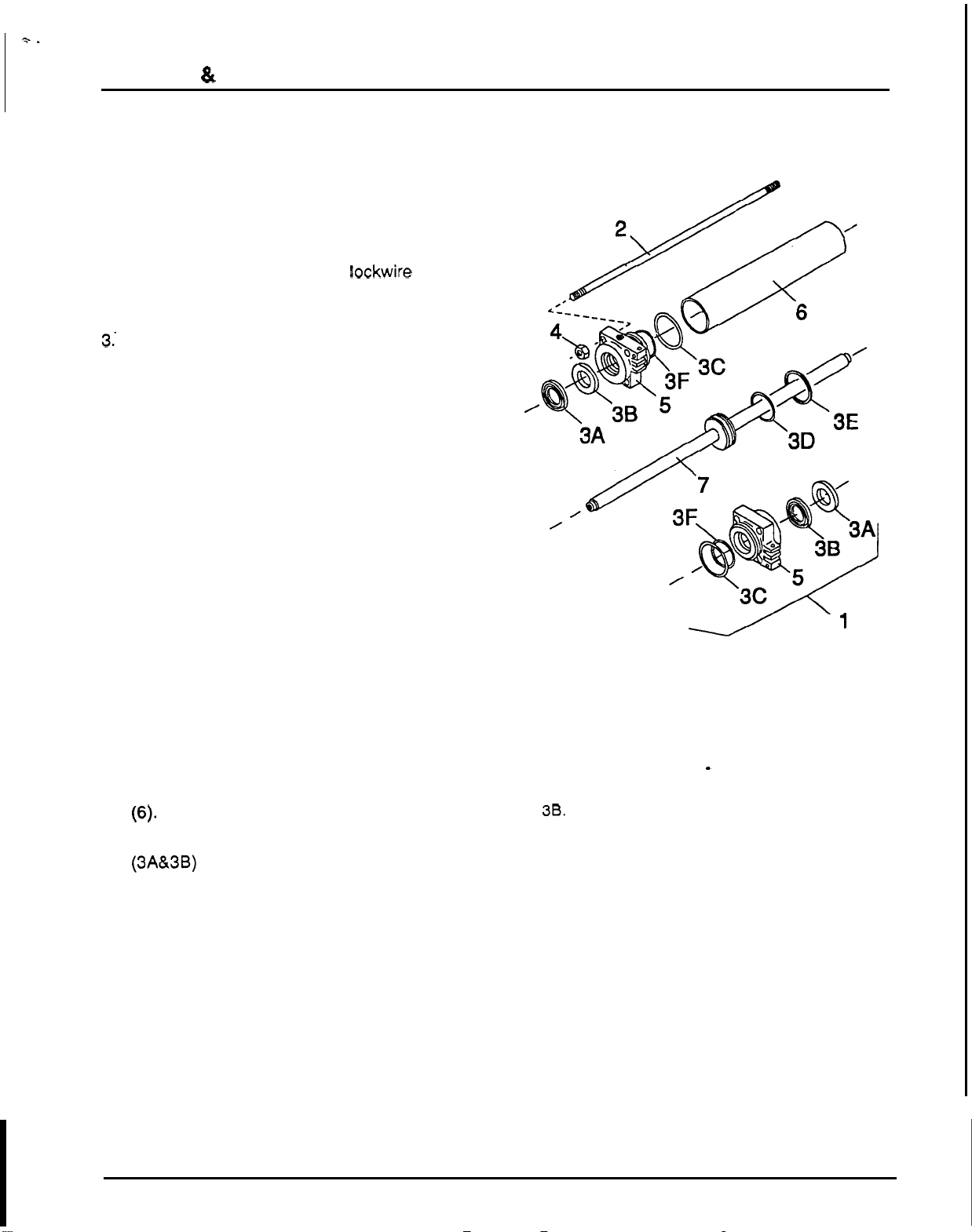
-
SERVICE
&
MAINTENANCE INSTRUCTIONS
4.
Clean all components in solvent and blow dry
with low pressure air.
ASSEMBLY
1.
Lubricate O
-
rings and seals with clean
hydraulic fluid.
2.
Assemble using exploded view. Note that items
(48)
and
(4H)
are used with lockwire cylinder
only. Note that items
(4J)
and
(9)
are used with
threaded plug cylinder only.
3.. Torque locknut to
175
ft
-
lbs.
4.
Carefully insert piston and rod into barrel.
It
will
be necessary to compress wear ring and piston
seal to avoid damage during insertion.
Lock Wire Installation
Rotate gland until lock wire starting hole in gland is
visible through slot in barrel. Insert lock wire hook
into hole and pull into groove by rotating gland until
wire is completely seated.
Threaded Plug Installation
Screw threaded plug into cylinder using a spanner
wrench, or carefully use a punch and hammer.
Swing Cylinder (Figure
31)
DISASSEMBLY
1.
Remove hex nuts
(4)
from tie rods
(2).
2.
Remove both piston rod guides
(5)
from barrel
3. Remove and discard rod wiper and seal
4.
Remove rod assembly (7) from barrel
(6).
5.
Clean
all
components in solvent and blow dry
(6)-
(3A&3B) from each piston rod guide.
Remove and discard seals.
with low pressure air.
ASSEMBLY
1.
Lubricate seals and wipers with clean hydraulic
fluid.
2.
Install O
-
ring
(3D)
in groove on piston and
piston seal
(3E)
on top
of
O
-
ring in piston
groove.
1.
Hydraulic swing cylinder complete
2.
7/16
x
16
"
Tie
rod
3.
Seal
kit
(contains
3A
-
3F)
3A.
Rod
wiper
38.
Rod
seal
3C.
Gland
static
seal
3D.
O
-
Ring
3E.
Piston seal
3F.
Back
-
up ring
4.
7/16
Hex
nut
5.
Piston rod guide
6.
Barrel
7.
Rod assembly
Figure
31.
Swing Cylinder
41

3.
4.
5.
Carefully insert piston and rod into barrel.
6.
Piston seal must be compressed when
inserting.
Carefully insert piston and rod into barrel.
Piston seal must be compressed when
inserting.
Place back
-
up ring
(3F),
if
required, into groove
7.
on piston rod guide
(5)
then install O
-
ring
(3C)
into groove. Install rod seals
(3B),
with
V
-
groove toward piston, into each piston rod
guide outer groove.
SERVICE
&
MAINTENANCE INSTRUCTIONS
.i
When installing piston rod guides to barrel,
I
make sure chain fastening lugs are positioned
properly. With cylinder in front of you, place
right rod guide with chain lugs on bottom and
left rod guide with chain lugs on top as
illustrated.
Insert the four tie rods
(2)
with rod guide chain
hole centerlines parallel. Torque nuts
to
40
-
45
ft
-
lbs.
NOTES
,
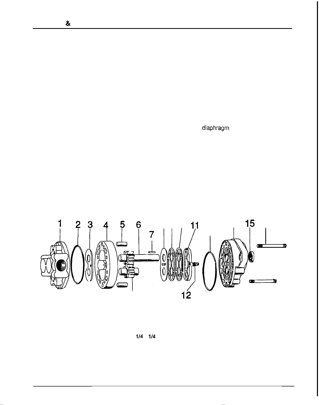
SERVICE
&
MAINTENANCE INSTRUCTIONS
HYDRAULIC PUMP REPAIR
(Figure
32)
Pump repair is limited to seal replacement.
DISASSEMBLY
1.
Remove key
(7)
from shaft.
2.
Clean outside of pump thoroughly.
3.
Clamp pump in vise,
shaft
up.
4.
Remove tie bolts
(1
6),
four each.
5.
Remove tie bolts
(1
7), four each.
6.
Use sharp tool to mark across front plate, body
and back plate. This will assure proper
reassembly.
123
7.
Remove pump from vise, hold pump in hands
and bump shaft against a wooden block to
separate front plate
(14)
from back plate
(1).
Body
(4)
will remain with either front plate
or
back plate.
8.
To separate body from section it remains with,
place drive gear
(6)
in bearing and tap
protruding end with plastic hammer.
9.
Remove thrust plate.
(3)
from back plate.
10.
Remove O
-
ring
(2)
from back plate.
11.
Remove O
-
ring
(2)
from front plate.
12.
Remove .,diaphragm
(8)
from front plate by
13.
Lift springs
(1
2)
two
each, and steel balls
(13)
14.
Lift back
-
up gasket
(9)
and protector gasket
15.
Lift diaphragm seal
(1 1)
from front plate.
16.
Remove shaft seal
(1
5)
from plate.
prying with sharp tool.
two
each, from front plate.
(1
0)
from front plate.
456
8
910
11
2
I
18
i
0
12
13
14
15
16
I-'
-
17
1. Back plate assembly
7.
114
x
114
x
15/16 Key
13. Steel ball
2. O-Ring
8.
Diaphragm
14. Front plate assembly
3. Thrust plate
9.
Back-up gasket
15. Shaft seal
4.
Body
10.
Protector gasket
16.
Tie
bolt
5.
Dowel pin
11. Diaphragm seal 17. Tie
bolt
6.
Drive gear assembly 12. Spring 18. Idler gear assembly
Figure
32.
Pump Assembly
43
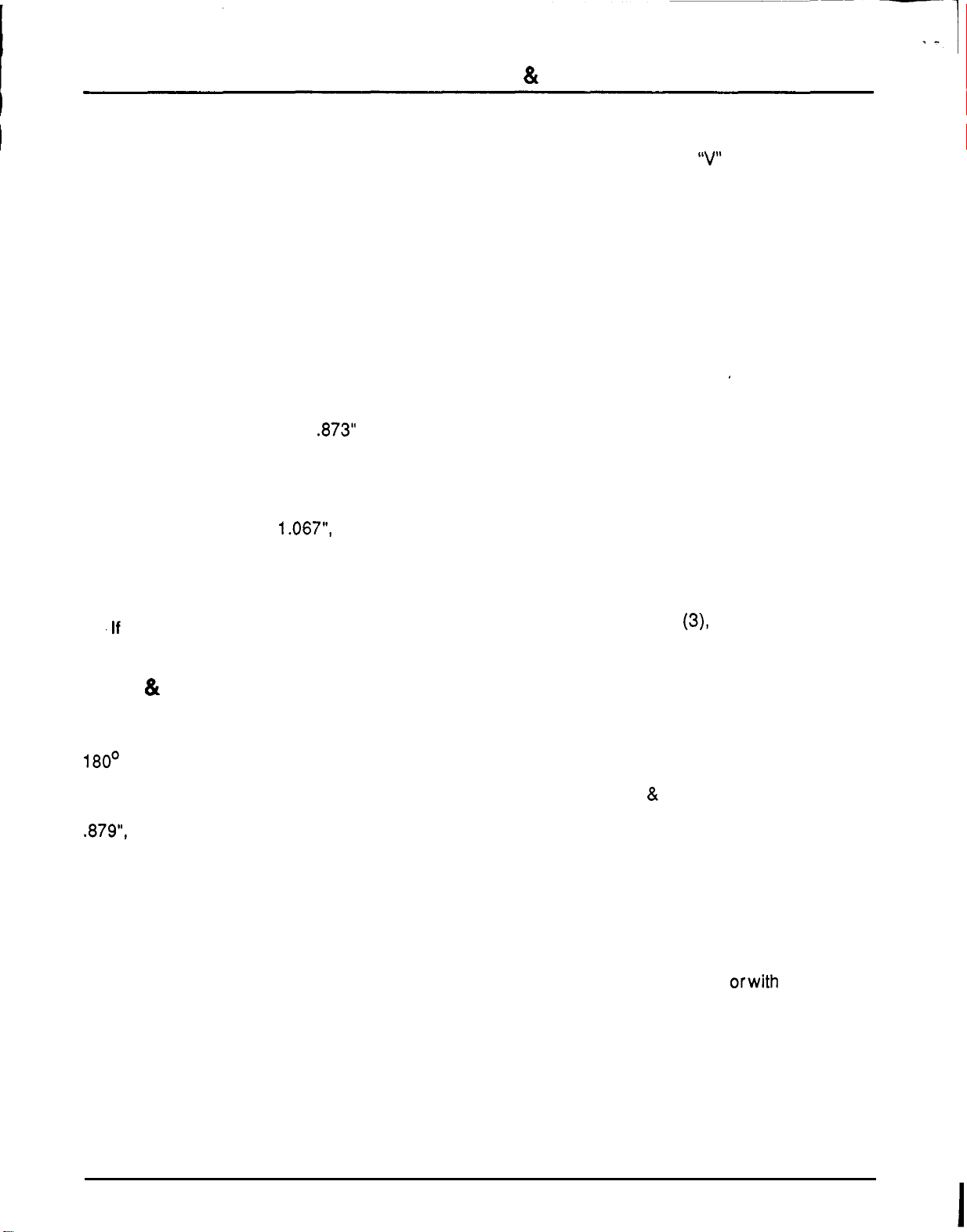
SERVICE
&
MAINTENANCE INSTRUCTIONS
I
I
INSPECT PARTS
FOR
WEAR
General
Clean and dry
all
parts.
Remove nicks and burrs from all parts with emery
cloth.
Gear
Assembly
1. Inspect drive gear shaft (6) for broken keyway.
2. Inspect both the drive gear and idler gear shafts
at bearing points and seal area for rough
surfaces and excessive wear.
3.
If
shaft measures less than .873" in diameter in
bearing area, the pump should be replaced.
4. Inspect gear face for scoring and excessive
wear.
5.
If
gear width is below 1.067", pump should be
replaced.
6. Assure that snap rings are in grooves on either
side of drive and idler gears.
7.
.If
edges of gear teeth are sharp, break edge
with emery cloth.
Front
&
Back
Plates
Oil grooves in bearings in both front and back
plates should be
in
line with dowel pin holes and
180' apart. This positions the oil grooves closest
to the respective pin holes.
If
ID of bearings in front plate
or
back plate exceeds
.879",
pump should be replaced.
Bearings in front plate should be flush with islands
in
groove pattern.
Body
Check inside gear pockets for excessive scoring
or
wear.
Pump should be replaced
if
the
ID
(internal
diameter) of the gear pocket exceeds 2.1
07
"
.
REASSEMBLY
1. The thrust plate, diaphragm, back
-
up gasket,
protector gasket, diaphragm seal, shaft seal
and
O
-
rings should be replaced as new parts.
Install O
-
ring (2) in groove in front plate (14).
2.
Tuck diaphragm seal (1 1) into grooves in front
plate with open part of
"V
section down. (Use
dull tool.)
3. Press protector gasket
(10)
and back
-
up
gasket (9) into diaphragm seal.
4.
Drop steel balls (1 3) into respective seats and
place springs (12) over balls.
5.
Place diaphragm
(8)
on top
of
back
-
up gasket,
bronze face up.
6.
Entire diaphragm must fit inside the raised rim
of the diaphragm seal.
7. Dip gear assemblies into oil and slip into front
plate bearings.
8. Install dowel pins
(5)
in body (4).
9.
Apply a thin coat of heavy grease to both milled
faces of body. Slip body over gears onto front
plate (half moon port cavities in body must face
away from front plate). Note small drilled hole
in one of the cavities. This hole must be on
pressure side
of
pump.
10. Install thrust plate
(3), bronze face toward
gears. Side with mid
-
section cut away must be
on suction side of pump. Thrust plate must fit
inside gear pockets.
11. Install O
-
ring (2) in groove in back plate
(1).
12. Slide back plate over gear shafts until dowel
pins are engaged.
13. Install bolts
(1
6
&
17) and tighten evenly
to
40
ft
-
lbs. torque.
14. Work shaft seal over drive gear shaft, taking
care not to cut rubber sealing
lip.
(Oil seal
liberally
before
installing.)
15. Place 1
-
5/1 6
"
O.D. (outside diameter) sleeve
over shaft and seat shaft seal by driving with
plastic hammer.
16.
Rotate pump shaft by hand orwith pliers. Pump
will have small amount
of
drag, but should turn
freely after short period of use.
I
44

I
;'
SERVICE
&
MAINTENANCE INSTRUCTIONS
GENERAL PUMP INFORMATION
Direction of rotation on all
"L"
Series pumps with
two
ball checks in the front plate may be reversed
by removing the tie bolts and rotating back plate,
thrust plate and body
180'.
It is important that the relationship of the back plate,
thrust plate, body and front plate is correct. You will
note
two
half moon cavities in the body which must
face away from the front plate. Note also a small
drilled hole in one
of
these cavities. This hole must
be
on the pressure side of the pump. Side
of
thrust
plate with mid
-
section cut away must be on suction
side of pump.
Suction side of back plate is always the side with
the larger port boss. Pumps using only one ball
check in the front plate cannot be reversed.
Refer to Placing Pump Back in Service, page 21.
Placing Pump Back Into
Service
1.
Before starting pump, it is recommended to
prime it first.
2.
If shop test stand is available, the following
procedure for testing rebuilt pumps is
recommended:
a.
Mount pump on test stand, making sure that
the proper level of clean oil is available in the
reservoir. Check suction line for leaks and
obstructions.
b.
Start pump and run for three minutes at
200
psi pressure.
c.
Intermittently
load
pump
to
500
psi
for
three
minutes.
d.
Intermittently load pump to 1000 psi for three
minutes.
e. Intermittently load pump to 2000 psi for three
minutes.
f.
Relieve pressure, remove pump from test
stand and check for looseness of drive shaft.
Check for leaks.
3.
It shop test stand is not available, the following
procedure for testing rebuilt pumps is
recommended:
a.
Mount pump on equipment and run pump at
1/2 engine speed at 200 psi pressure.
b.
By operating control valve, build pressure
intermittently for three minutes.
c. Increase engine speed to full throttle and
build pressure intermittently for three
minutes.
d.
Idle engine and check for leaks.
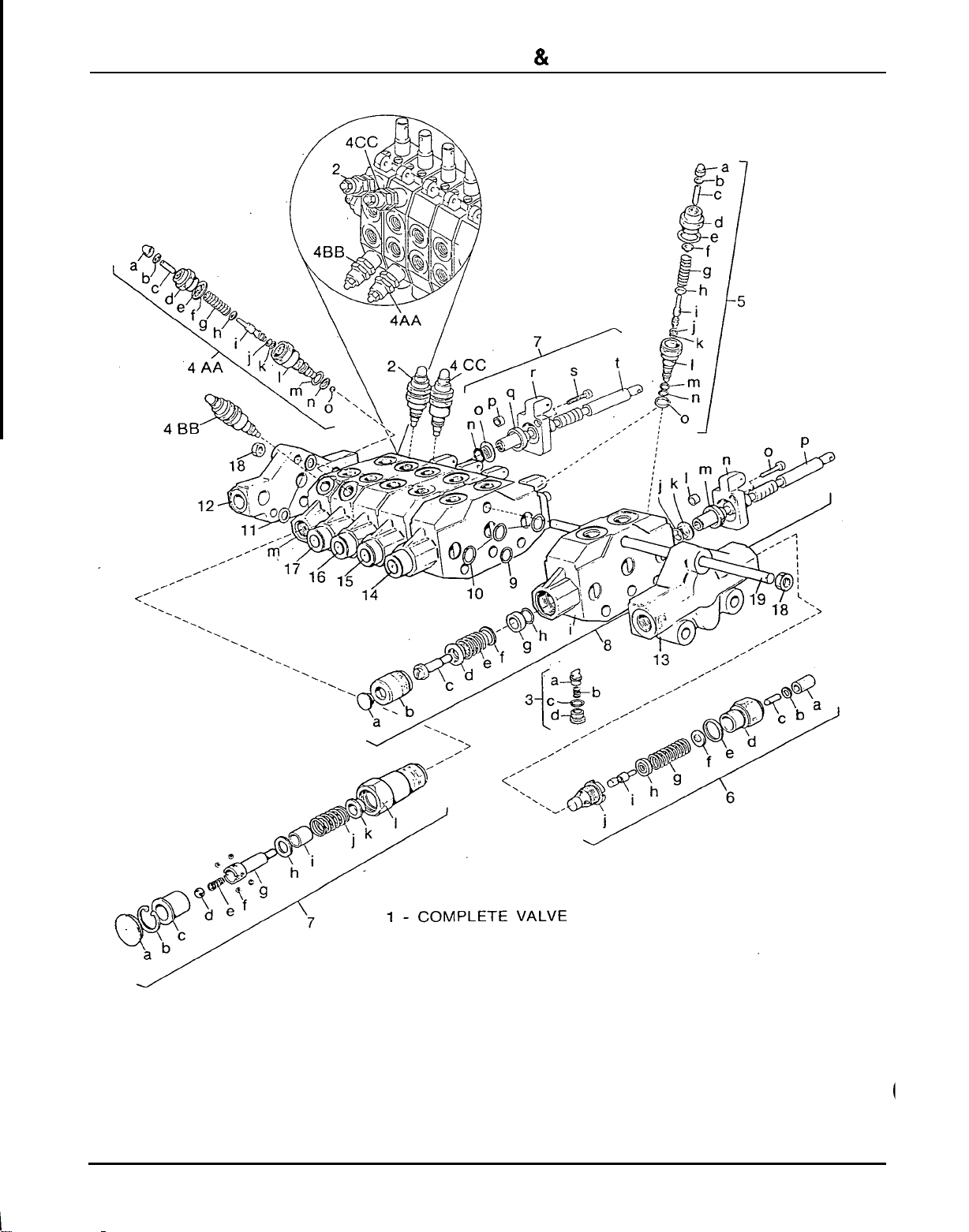
SERVICE
&
MAINTENANCE INSTRUCTIONS
,
-
-
I
Figure 33.
Hydraulic Valve Repair
46

SERVICE
&
MAINTENANCE INSTRUCTIONS
1. Complete hydraulic valve
2. Shodddampening valve, 3500 psi
3. Check valve assembly
a. Poppet
b.
Spring
c. Seal
d. Car plug
4AA.
ShocWdampening valve, 2000 psi
a. Cap nut
b.
Washer
c. Adjusting screw
d. Retainer
e. Rear spring washer
f.
Copper washer
g. Spring for relief valve
h. Front spring washer
i.
Valve poppet
j.
Back
-
up ring
k.
Seal
1.
Valve seat
m. Back
-
up ring
n. Washer
0.
Ball, Dia. 5
4BB.
ShocWdampening valve, 2500 psi
4CC.
ShocWdampening valve,
2000
psi
5.
ShocWdampening valve, 2500 psi
a. Cap nut
b.
Washer
c. Adjusting screw
d. Retainer
e.
Copper washer
f.
Rear spring washer
g. Spring for relief valve
h. Front spring washer
i.
Valve poppet
j.
Back
-
up ring
k.
Seal
1.
Valve seat
m. Back
-
up ring
n. Seal
0.
Washer
6.
1350
-
3000 Psi Relief valve assembly
a. Cap nut
b.
Copper washer
c.
Adjusting screw
d.
Retainer
e. Copper washer
1. Rear spring washer
g. Spring
h.
Front spring washer
I
i.
Valve poppet
j.
Valve seat
7.
Spool position control
04
assembly
a. Plug for
04
positioner
b. Snap ring
c. Bushing for
04
positioner
d. Ball
e. Spring
f.
Ball
g. Connecting bolt
h. Washer
i.
Spacer
j.
Spring for
04
positioner
k.
Spring flange
1.
Housing
m. Boom segment
n. O
-
Ring
0.
Flanged washer
p. Dowel bushing
q.
Scraper
r. Lever bracket
s.
Cap screw
1.
Spool
8.
Dipstick segment complete
a. Plug
b. Housing
c. Connecting bolt
d. Spring cap
e. Spring
f. Spring cap
g.
Spacer
h. O
-
Ring
i.
Dipstick segment
j.
O
-
Ring
k.
Flanged washer
1.
Dowel bushing
m.
Scraper
n. Lever bracket
0.
Cap screw
p.
Spool
9. Seal
10. Seal
1 1. Spacer
12. Standard exhaust section
13.
Front port inlet section
14.
Bucket segment
15. Right stabilizer segment
16. Left stabilizer segment
17. Swing segment
18.
Nut
19. Tie rod
47
SERVICE
&
MAINTENANCE INSTRUCTIONS
HYDRAULIC VALVE REPAIR
(Figure
34)
Valve repair should be accomplished in a clean
work place. Individual components for many
of
the
assemblies are not available as repair parts. This
will simplify repair and allow you to replace
complete assemblies.
~
Pressure Settings on
ShocWDampenmg Valves
Pressure settings on shocWdampening valves are
preset at the factory. Although they are adjustable,
they must not be reset in the field using backhoe
hydraulic system. The backhoe pump will separate
or
crack
if
system pressure exceeds the maximum.
Relief valve adjustment requires
a
test bench and
accurate gauges.
Adjusting System Relief Valve
Pressure
Place a pressure gauge in the pump pressure line
at the relief valve. When installing pressure gauge,
be sure to use steel fittings that will withstand
working pressure up to
5000
psi. Remove cap nut
(6a). Adjusting screw (6c) has a hex socket
-
rotate
screw clockwise to increase pressure and
counter
-
clockwise to decrease pressure. Start
tractor PTO and set system relief valve pressure at
2000
psi. When pressure
is
adjusted, shut tractor
PTO
and
tractor
off.
Replace cap nut (6a) on
system valve.
Re lacing ShocWDarnpening
Va
P
ves
It is not necessary
to
remove console valve from
console to replace
shock/dampening valve
cartridges. Remove console cover and replace
them. Be sure you install valve cartridges set at the
correct pressure. Valves are similar and can be
easily mixed up.
.
ShocWDampening
Pressure
2
3500
PSI
.
4AA
4BB
2000
PSI
2500
PSI
5
2000
PSI
4cc
2500
PSI
Valve
Setting
Segment Replacement
1.
2.
3.
Relieve system pressure and remove valve
from backhoe. Remove tie rods and separate
the valve sections.
Replace defective sections as necessary.
Make sure you install
two
spacers between
each section of each tie rod. Note the location
of O
-
rings
(9
&
lo)..
They must be placed in
location between valve sections as shown.
When assembling valve sections, use care
when torquing nuts on tie rods. This must be
done in steps
-
that is to say, gradually
increasing the tightening torque up to
13
ft
-
lbs.
in an alternating sequence. Non
-
uniform
or
excessive tightening can cause binding of
spools. Failure to attain the proper torque can
result
in
leaks. Always use
a
torque wrench.
40
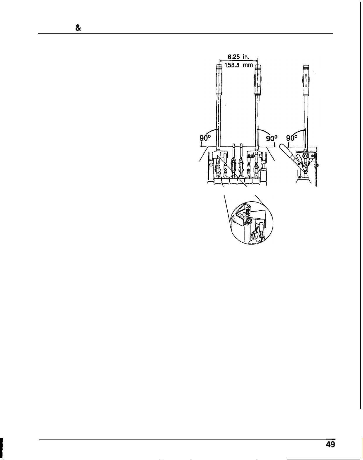
SERVICE
&
MAINTENANCE INSTRUCTIONS
Installing Valve (Figure
34)
1.
2.
3.
4.
5.
Reconnect control linkage to valve.
Adjustment of the linkage should not be
necessary unless
it
was disturbed.
Control handles should
be
positioned with
console as shown.
When completing a maintenance function on
the valve, perform a functional test by placing
control handles in their various positions and
make certain the correct operation occurs
corresponding
to
the decals on the operator’s
console. Pay specific attention to the float
position of the boom.
Do
not operate backhoe
if
functions
differ
from the decal.
If the functions differ from the decal, check
to
make sure control linkage is correctly installed
and check plumbing schematics to make sure
hoses are correctly connected.
REAR
VIEW
SIDE
VIEW
Figure
34.
Linkage Installation
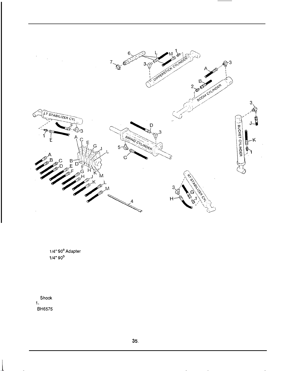
PLUMBING SCHEMATIC
PLUMBING SCHEMATIC
Use this figure and Figure 36 for plumbing
schematics. Letters are for hose
connection locations for both Figure 35
and Figure 36.
1. 114
x
114
"
Straight adapter union
3.114
x
114" 90OAdapter union
4. 114
x
114" 90' Adapter union with
5.
Relief valve
6.
Shock dampening valve, 2500 psi
7.
Shock dampening valve, 2000 psi
8.
Shock dampening valve, 2000 psi
9. Shock dampening valve, 3500 psi
10.
Shock dampening valve, 2500 psi
1
1. Shock dampening valve, 2500 psi
The
BH6575 uses a 114
x
114
"
straight
adapter union with 3/32
"
restrictor in the
rod end of the boom cylinder.
111 6
"
restrictor
LEGEND
A
from top
port
of
boom valve segment to piston end of boom cylinder
B
from bottom
port
of valve boom segment to rod end of boom cylinder
C
from top
port
of valve swing segment to bottom left
port
of swing cylinder
D
from bottom
port
of valve swing segment to top right
port
of swing cylinder
E
from top
port
of valve left stabilizer segment to rod end of left stabilizer cylinder.
F
from bottom
port
of valve left stabilizer segment to piston end of left stabilizer
G
from top
port
of
valve right stabilizer segment to rod end of right stabilizer
H
from bottom
port
of valve right stabilizer segment to piston end of right
J
from top
port
of valve bucket segment to piston end of bucket cylinder
K
from bottom
port
of valve bucket segment to rod end of bucket cylinder
L
from top
port
of valve dipperstick segment to piston end of dipperstick cylinder.
M
from bottom
port
of valve dipperstick segment to rod end of dipperstick
cylinder
cylinder
stabilizer cylinder
cylinder.
Figure
35.
Plumbing
Schematic
50
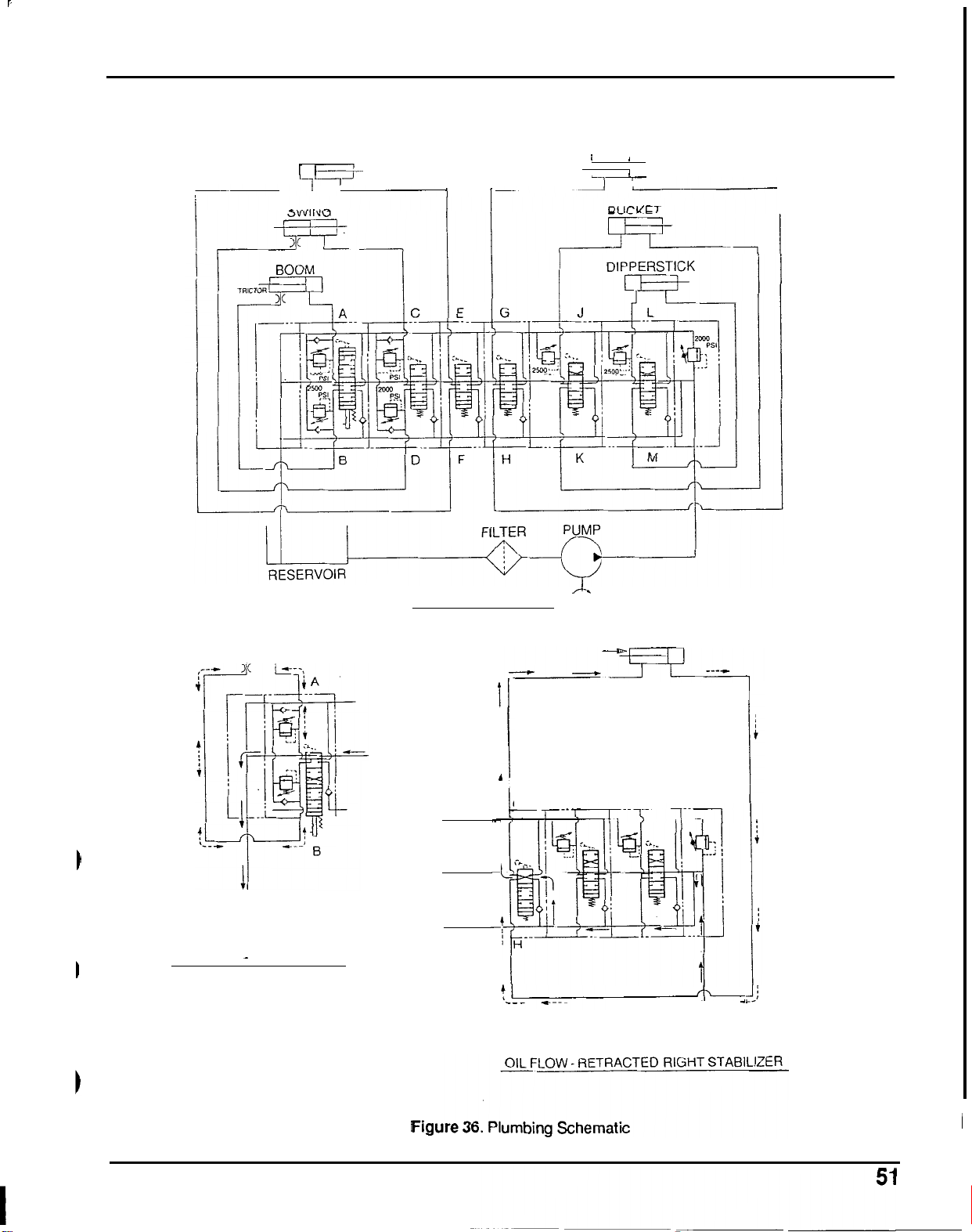
PLUMBING SCHEMATIC
PLUMBING
SCHEMATIC (Cont.)
LT. STABILIZER
RT.
STABILIZER
I
I
1
t+
I
I
I
I
RES
-
=.
FROM
PUMP
NEUTRAL POSITION
m
T
O
RE
S
ERVOIR
OIL FLOW
-
BOOM FLOAT
4
I
TO
RESERVOIR
-
-
-
-
1
1
G
m
FROM PUMP
*
__
-

SPECIFICATIONS
SPECIFICATIONS
REACH BELOW GRADE (Standard Bucket)
Maximum
.................
With
two
foot flat bottom trench*
.....
LOADING HEIGHT'
REACH
From center of swing mast pivot point
. .
BUCKET ARC
SWING WORKING ARC
OPERATING PRESSURE
Digging'
.................
Swing'
.....
;
............
STABILIZER SPREAD
BOOM CYLINDER
Bore
...................
Stroke
..................
DIPPERSTICK CYLINDER
Bore
...................
Stroke
..................
Digging Force'
..............
Bore
...................
Stroke
..................
Digging Force
..............
Bore
...................
Stroke
..................
BUCKETCYLINDER
SWING CYLINDER
91.8
"
90ll
68.0
1
12.2
"
175O
180'
2000
psi
2000
psi
52.5
"
-
89.5
"
2.5
"
1
6.75
"
2.0
"
1
6.75
"
2275
Ibs.
2.0
"
1 6.75
"
2600
Ibs.
2.5
"
10.62
"
2332
rnm
2286
rnm
1727
rnm
2845
rnm
13.8
MPa
13.8
MPa
1333
-
2273
mrn
63.5
mm
425.5
rnm
50.8
mm
425.5
rnrn
1032
kg
50.8
rnrn
425.5
mm
1179
kg
63.5
rnm
269.7
mrn
BUCKET CAPACITY
HEAPED
STRUCK
8
Inches
.................
77 ft3.022
m3
.65
ft3
.018
m3
16
Inches
.................
1.71
ft3.048
m3
1.37
ft?
.039
m3
18
Inches
.................
2.02 ft3.057
m3
1.55
ft3.044
m3
12
Inches
.................
1.23
ft?
.035
m3
1.00
fta3
.028
m3
24
Inches
.................
3.32
ft3.094
m3
2.10
fL3
.060
m3
*Per SAE
J49
Standard.
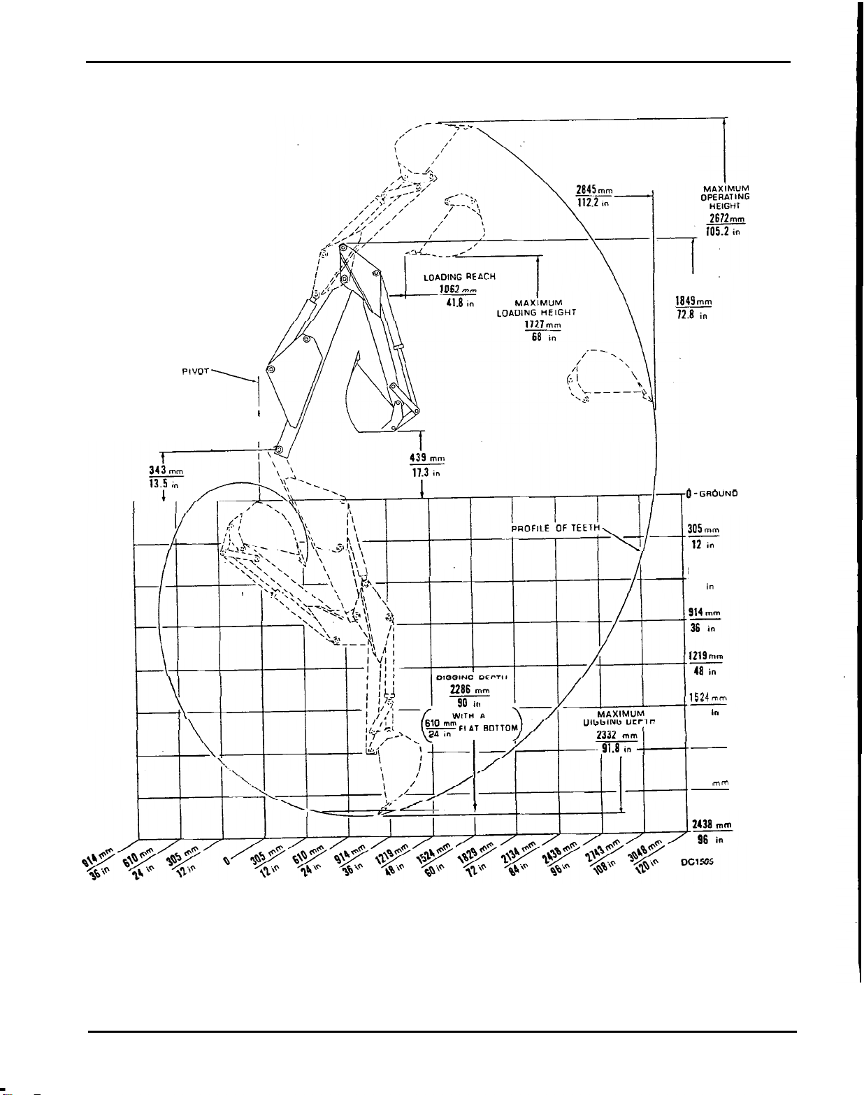
SPECIFICATIONS
SPECIFICATIONS (Cont.)
CENTER
OF
SWING
PIVOT
I
MAXIMUM
REACH
TRAN
S
PORT
HEIGHT
1
~GROUNO LINE
24
in
1524mm
60
in
1829
mm
72
in
-
2134
mm
84
in
53

NOTES
SPECIFICATIONS
54

..
li
INDEX
TO
PARTS
LISTS
INDEX
TO
PARTS
LISTS
MAIN FRAME ASSEMBLY
..............
56
.
57
BACKHOE SUB
-
FRAME
...............
58
.
59
BOOM ASSEMBLY
...................
60
DIPPERSTICK
&
BUCKET ASSEMBLY
........
61
HOSES
&
FITTINGS
...................
62
PUMP
&
TANK ASSEMBLY
............
'
...
63
HYDRAULIC GEAR PUMP ASSEMBLY
........
64
VALVE CONTROLS
&
HARDWARE
..........
65
CONSOLE VALVE ASSEMBLY
.............
66
SWINGCYLINDER
...................
67
BOOM
&
DIPPERSTICK CYLINDER
..........
68
STABILIZER CYLINDER
................
69
BUCKET CYLINDER
..................
70
55
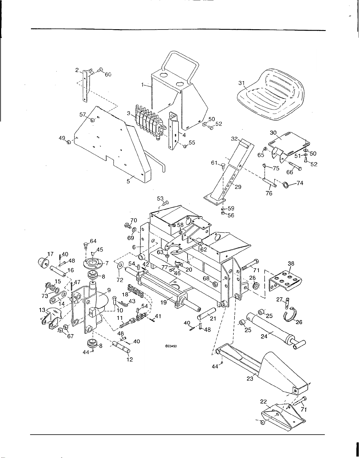
MAIN FRAME ASSEMBLY
MAIN FRAME ASSEMBLY
DO3453
I
68
56

1
-.
MAIN FRAME ASSEMBLY
MAIN FRAME ASSEMBLY
Fig
No.
1
2
3
4
5
6
7
8
9
10
11
12
13
14
15
16
17
18
19
20
21
22
23
24
25
26
27
28
29
30
31
32
35
No.
Used
1
1
1
1
1
1
1
2
1
1
2
1
1
1
1
1
2
2
1
2
Description
Console cover
Right valve bracket assy
Console valve
Left valve bracket asy
Valve mounting plate asy
Frame assembly, main
Cap asy, kingpost
1
-
1/2
ID
Ball bushing
Kingpost weldment assy
Swing lock pin
Bolt,
chain tension
Pivot pin, boom
Guide, hose
Plate, latch
.072
x
.62
Compression spring
Pin, pivot
Pad asy, bumper
Chain, swing
Swing cylinder assy.
(see
page
65
for breakdown)
Clamp, hose
Pin, pivot
Pad assy, stabilizer
Stabilizer assembly
2
x
14
-
1/2
Stabilizer cylinder (see
page
67
for breakdown)
13/16
x
1
-
1/4
x
1
Bushing
Hose clamp
Shield, hose protector
Grommet,.25'x
1
.O
x
1.38
Lower seat support
Seat bracket assy.
Seat
Upper seat suuport
Complete label set
BH6575
Fig
No.
'40
'41
'42
'43
'44
'45
'46
'47
48
49
'50
'51
52
'53
54
55
'56
57
'58
'59
'60
'61
'62
'63
64
'65
'66
'67
'68
'69
70
71
72
73
74
HARDWARE
Description
1/16
x
1/2
Cotter pin
3/32
x
1/2
Cotter pin
3/32
x
1
-
1/2
Cotter pin
3/16
Safety pin
Straight
1/4
tapered thread grease fitting
1/4
-
28
Threaded
90'
grease fitting
1/4
NC
x
3/4
Hex head cap screw
GR5
1/4
x
1
-
1/2
Cotter pin
1/4
x
1
-7/8
Clevis pin
5/16
NC Flanged hex locknut
5/16
Standard flat washer
5/16
Standard lockwasher
5/16
NC
x
3/4
Hex head cap screw
GR5
5/16
NC
x
3/4
Carriage bolt
Pin, chain
8mm
x
1.25mm
Pitch hex nut
3/18
NC Hex nut, plated
3/8
NC Flanged hex locknut
3/8
NC Hex locknut
3/18
Standard lockwasher
3/8
NC
x
3/4
Carriage
bolt
3/8
NC
x
1
Carriage
bolt
3/8
NC
x
3
Hex head cap screw
GR5
7/16
NF Hex locknut
7/16
NF
x
1
-1/4
Wheel
bolt
1/2
NC Hex locknut
1/2
NC
x
4
Hex head cap screw GR5
5/8
NC Hex nut
3/4
NC Hex locknut
3/4
Standard lockwasher
314
NC
x
1
-1/2
Hex head cap screw GR5
3/4
NC
x
6 Hex head cap screw
GR5
13/16
x
.010
Shim washer
10
GA
x
1
-1/2
Washer
.11
x
1.1
OD
Split ring
75
3/16
x
1
Klik pin
76
1/2
x
4
-
1/2
Clevis pin
Obtain Locally
57
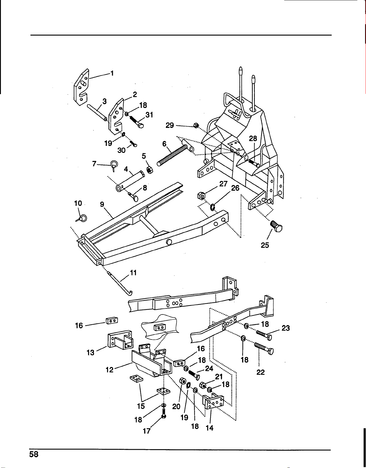
BACKHOE SUB
-
FRAME ASSEMBLY
BACKHOE SUB
-
FRAME ASSEMBLY

BACKHOE SUB
-
FRAME ASSEMBLY
BACKHOE SUB
-
FRAME ASSEMBLY
Ref
No.
1
2
3
4
5
6
7
8
9
10
11
12
13
14
15
16
Ref
No.
'1
7
'18
'19
'20
'21
'22
'23
'24
'25
'26
'27
'28
'29
'30
'31
N
O
.
Used
1
1
1
1
1
1
1
1
1
1
1
1
1
1
2
2
Description
Set plate, right
Set plate,
left
Cross shaft
Top link, outer
1
"
Nut
Top link, inner
Klik pin
Clevis pin, 19
x
76
mm
Backhoe sub
-
frame assy.
Klik pin,
114
x
1
-3/4
Pin,
19
x
397
mm
Crossmember assy.
Crossmember bracket, right
Crossmember bracket,
left
Set plate,
"
B
"
Set plate,
"
A
Hardware
Description
Bolt, 1/2
X
1-5/8"
GR
5
Flat washer, 1/2"
Lockwasher, 1/2
Nut,
1/2"
Locknut, 1/2"
Bolt,
1/2
x
2
"
GR 5
Bolt,
12
x
35mm
Lockwasher, 7/8"
Nut, 718"
Locknut,
314
BO^,
12
x
80
mm
Bolt, 1/2
X
1-3/4"
GR
5
Bolt, 7/8
X
2
-
1/2
GR
8
Bolt, 3/4 NC
X
3-112''
GR
5
Bok,
1/2 NC
X
1
-
1/4
GR
5
'
Obtain locally
59
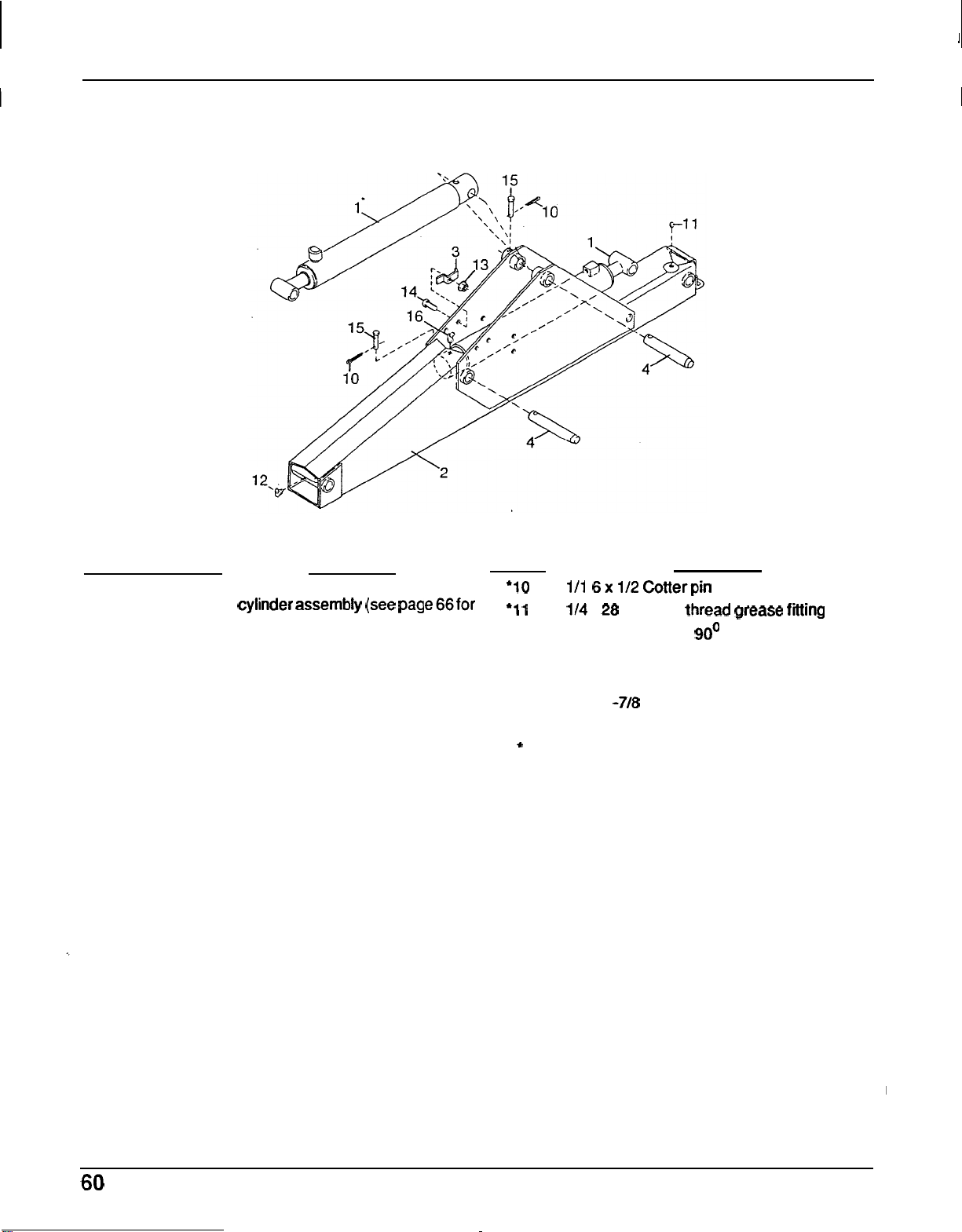
1
1
BOOM ASSEMBLY
BOOM ASSEMBLY
HARDWARE
Ref
No. No.
Used Description Ref
No.
Description
1 2 2
-
1/2
x
16
-
3/4 Hydraulic boom '10
111
6x 112 Cotterpin
2
1 Boom weldment assembly
3
1 Cylinder hose clamp
4
2
Pin,
Pivot
cylinder assembly (see page66for '1 1 1/4
-
28 Tapered thread grease fitting
breakdown)
'12 1/4
-
28 Threaded
90'
grease fitting
13 1/4 NC Flanged hex locknut
'14 1/4 NC
x
1
-
1/4 Hex head cap screw
GR5
15 1/4
x
1
-7/8 Clevis pin
'16
1/4
-
28 Threaded greese fitting
'
Obtain Locally
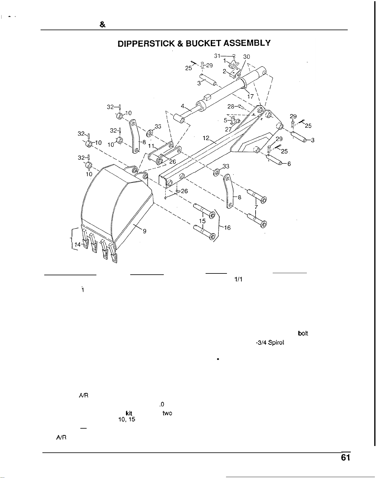
DIPPERSTICK
&
BUCKET ASSEMBLY
13
Ref
No.
No.
Used
1
1
2
i
3 2
4
1
5
2
6 1
7
2
8
2
9
1
10
4
11 1
12 1
13
A/R
15
2
16 1
17
-
Description
Socket,
SMV
emblem
Bracket,
SMV
socket
Pin, Pivot
2
x
16
-
3/4 Hydraulic cylinder (see
page 66
for
breakdown)
Hose clamp
Pivot pin, Boom
Rotating pivot pin
Link arm
12
"
Backhoe bucket
Pivot pin retaining sleeve
Bucket arm
Dipperstick weldment assy
Shank
&
tooth assy
Pivot pin assembly, 1
.O
x
7.25
HD Pin
kit
(includes
two
each
of
items 10,15
&
32)
Hose clamp
HARDWARE
Ref
No.
Description
'25
1/1 6
x
1/2 Cotter pin
'26
1/4
-
28 Tapered thread grease fitting
27
1/4 NC Flanged hex locknut
'28
1/4 NC
x
3/4 Hex head cap screw
GR5
29
1/4
x
1
-
7/8 Clevis
pin
30
5/16 NC Flanged hex locknut
31
5/16 NC
x
1/2 Carriage
bott
32
5/16
x
1 -3/4 Spirol
pin
33
1
"
SAE
Flat washer
Obtain Locally
NR
-
As
Required
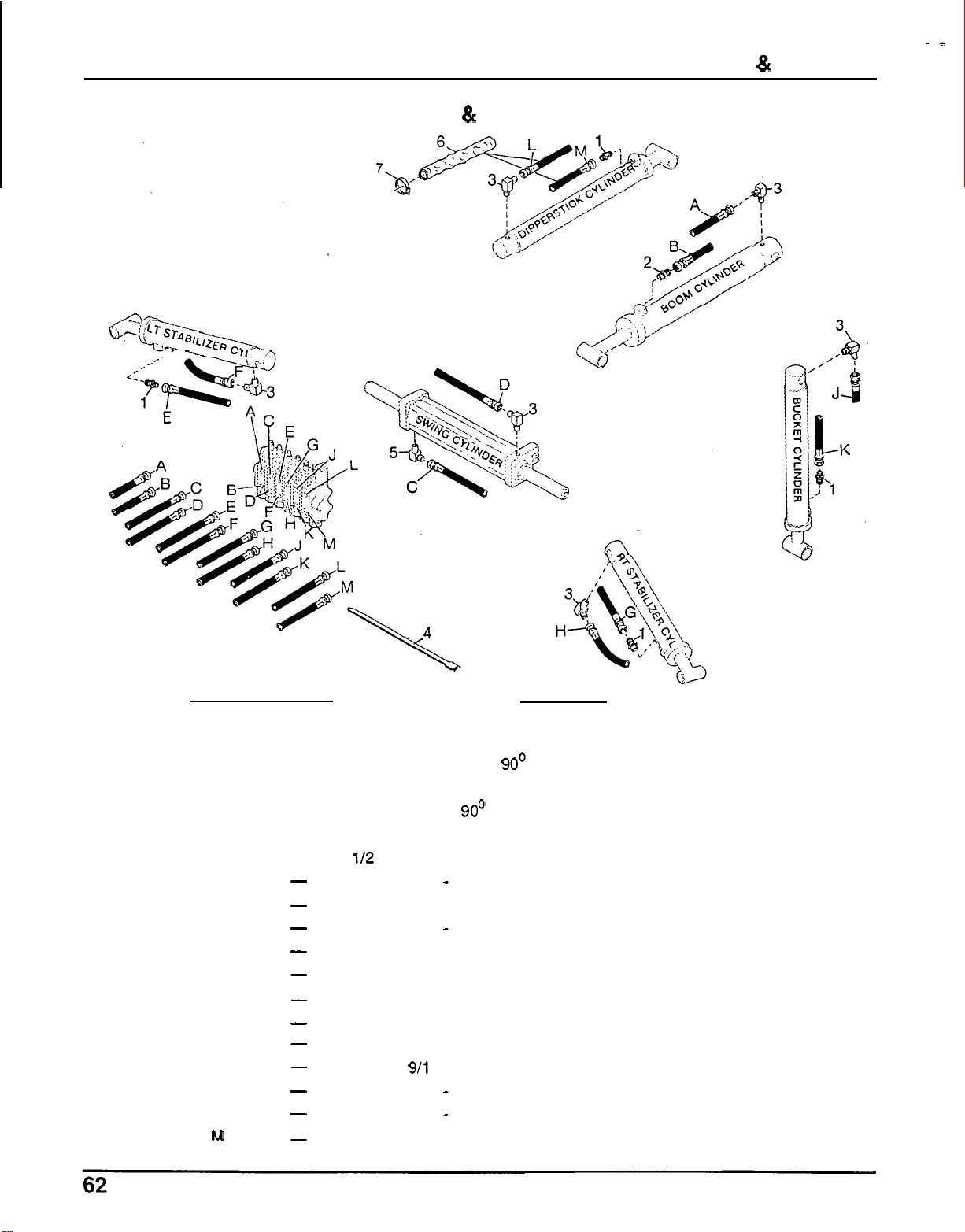
HOSES
&
FITTINGS
.*
HOSES
&
FITTINGS
i'
,
Ref
No.
No.
Used
1
4
2
1
3
6
4
2
5
1
6
2
7
2
A
B
C
D
E
F
-
G
-
H
I
K
L
M
-
-
-
-
-
-
-
-
-
-
Description
Connector
9/16
x
1/4 Male restrictor connector
9/16
-
18
x
1/4 NPTF 90' Fitting
Hydraulic hose tie,
7
"
long
9/16
x
1/4 NPT 90' Fitting with 1/16 restriction
Hose sleeve, 13
"
112 Hose screw clamp
Female 9/16
-
18
flare
x
99
high
pressure
hose
assembly
Female 9/16
-
18 flare
x
99 high pressure hose assembly
Female 9/16
-
18 flare
x
49 high pressure hose assembly
Female 9/16
-
18 flare
x
49 high pressure hose assembly
Female 9/16
-
18 flare
x
49 high pressure hose assembly
Female 9/16
-
18 flare
x
50
high pressure hose assembly
Female 9/16
-
18 flare
x
49 high pressure hose assembly
Female 9/16
-
18 flare
x
50
high pressure hose assembly
Female
911 6
-
18 flare
x
124 high pressure hose assembly
Female 9/16
-
18 flare
x
124 high pressure hose assembly
Female 9/16
-
18 flare
x
99 high pressure hose assembly
Female 9/16
-
18
flare
x
99 high pressure hose assembly
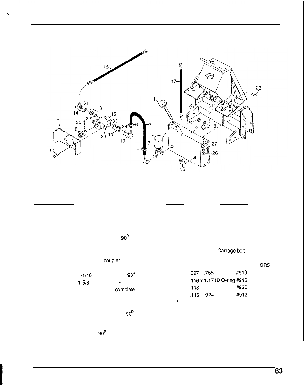
-,
.
PUMP
&TANK ASSEMBLY
PUMP &TANK ASSEMBLY
5
Ref
No.
No.
Used
1 1
2
1
3 1
4
1
5
1
6
2
7
1
8
1
9
1
10
1
11 1
12 1
13 1
14 1
15
1
16 1
17
1
18 1
Description
Tank breather cap with dipstick
Tank assembly
Filter
&
housing assy. complete
Filter element
3/4 Hose
x
3/4 pipe 90' elbow
1/2 Screw hose clamp
3/4
x
40 Low pressure suction hose
Pump drive
coupler
Pump mounting bracket
1
-1/16
-
12
x
3/4 Hose 90' elbow
1238
-
12
x
1
-
1/16
-
12 Reducer
Pump assembly
complete (see page
62 for breakdown)
1
-
5/16
-
12
x
7/8
-
14 Reducer with
O
-
ring
7/18
-
14
x
9/16 Flare 90' elbow
9/16 Flare
x
9/16 flare
x
34 high
pressure hose assembly
1/2
x
1/2 90' Pipe elbow
9/16
Flare
x
1/2
NPT
x
28
high
pressure hose assembly
Hose clamp
HARDWARE
Ref
No.
Description
'23
1/4 NC
x
3/4 Hex head cap screw
GR5
24
1/4 NC Flanged locknut
'25
5/16 NC
x
1
Cup point square head set
'26
3/8 NC Hex nut, plated
'27
3/8 Standard lockwasher
'28
3/8
NC
x
3/4 Carrage
bott
'29 1/2 NC Hex locknut
'30
1/2 NC
x
1
Hex head cap screw GR5
32
.116x 1.17IDO-ring#916
33 .118
x
1.48
ID
O-ring ##920
34
.116
x
.924
ID
O
-
ring #912
screw GD5
31
.097
x
.755 ID O
-
ring #910
Obtain Locally
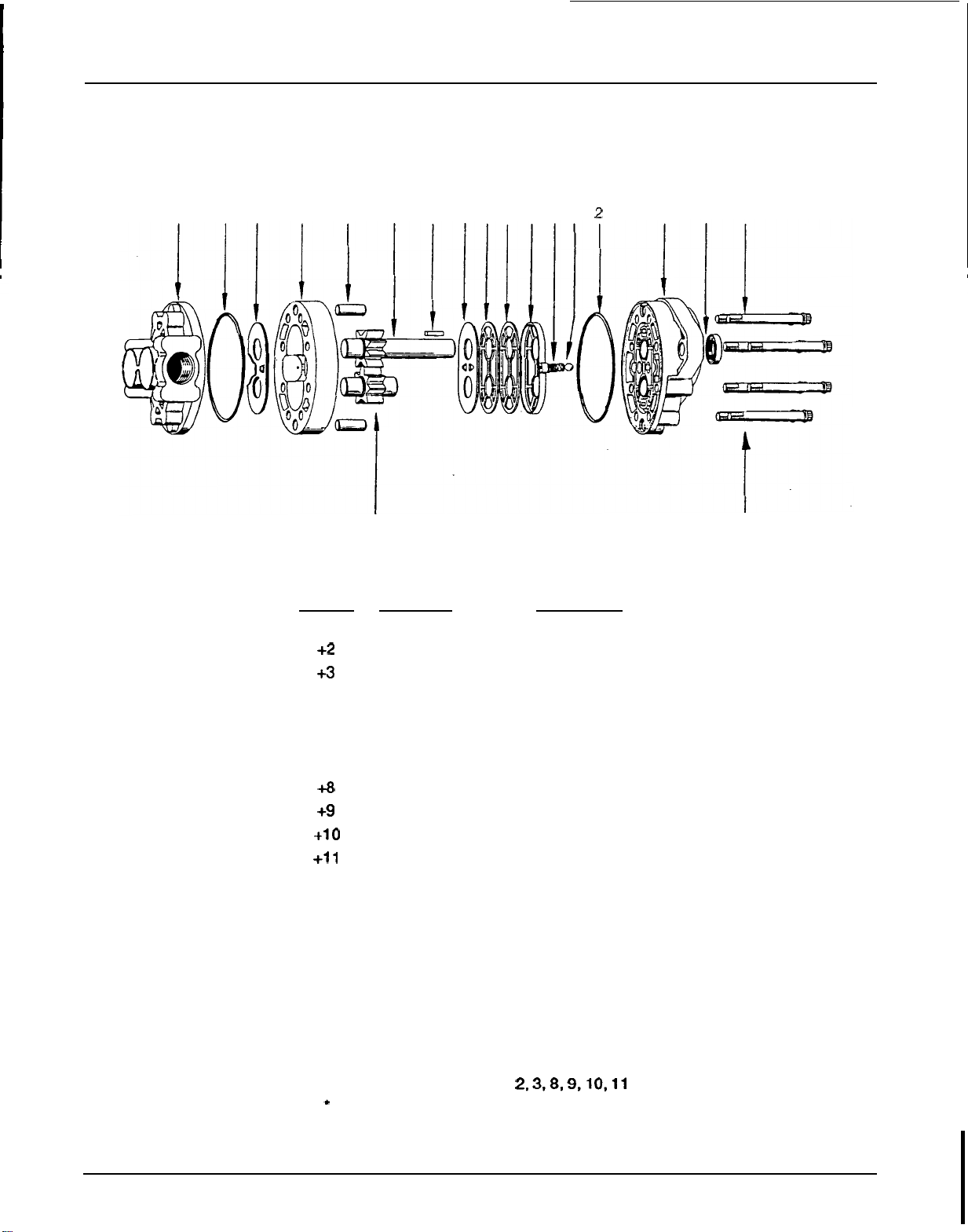
HYDRAULIC GEAR PUMP ASSEMBLY
HYDRAULIC GEAR PUMP ASSEMBLY
1
2
3
4
5
6
7
8
910111213 2 14
15
16
Ref
No.
'1
+2
+3
'4
'5
'6
7
+8
+9
18
No.
Used
1
2
1
1
2
1
1
1
1'
Description
Back plate assembly
O
-
Ring
Thrust
plate
Body
Dowel
pin
Drive gear assembly
1/4
x
1/4
x
15/16 Key
Diaphragm
Back
-
up gasket
+10 1
Protector gasket
+11 1
Diaphragm seal
'12
2
Spring
'13
2 Steel ball
'14 1
Front plate assembly
+15 1
Shaft seal
'1
6
4 Tie
bolt
'1
7
4
Tie
bolt
'1 8 1
Idler gear assembly
19 1
Gear pump assembly
20
1 Seal
kit
complete (includes
items
2,3,8,9,10,11
&
15)
'
Not
Serviceable
+
Not
Sold Separately
I
17
64
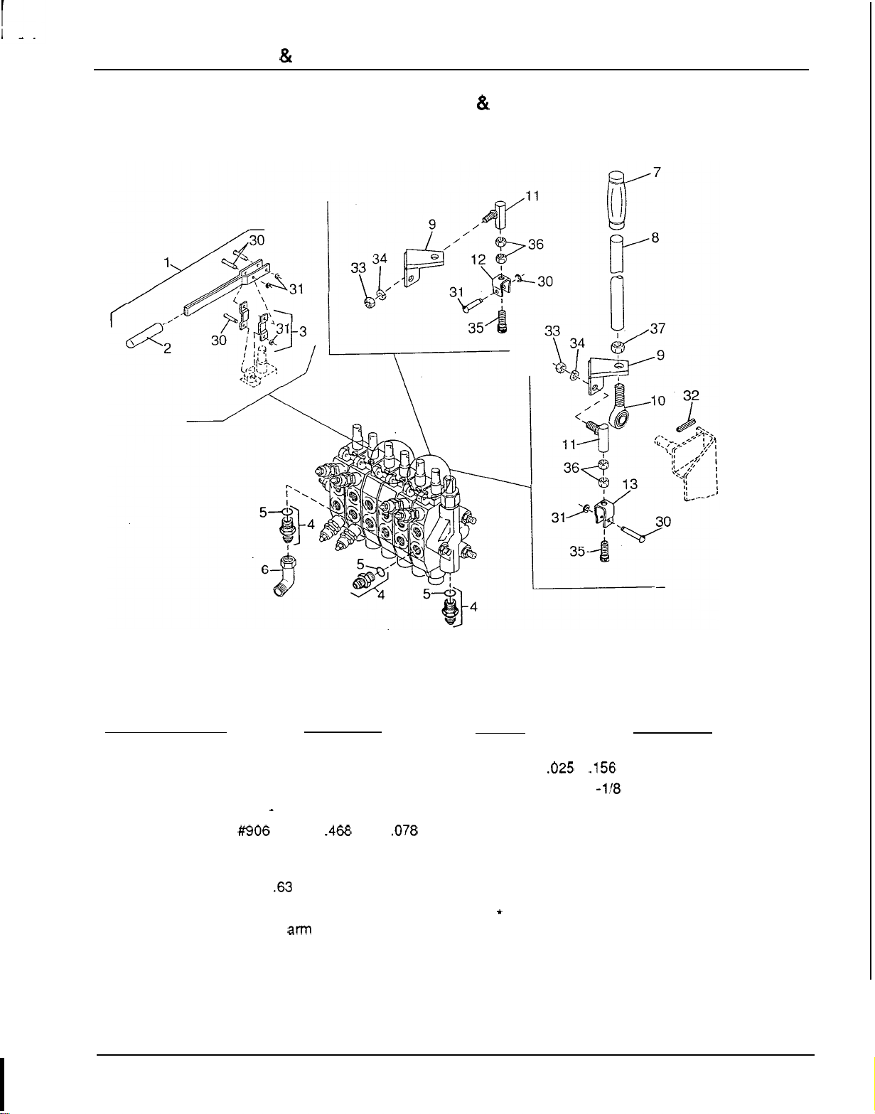
VALVE CONTROLS
&
HARDWARE
VALVE CONTROLS
&
HARDWARE
Ref
No. No.
Used
1
2
2
2
3 2
4 14
5
14
6 1
7
2
8
2
9
2
10 2
11
4
12
2
13 2
Description
Stabilizer handle assembly
Rubber handle
Stabilizer handle link kit
9/16
-
18 O
-
ring connector
#!306 O
-
ring, .468
ID
x
.078 cross
section
9/16
-
18
x
450 Swivel nut elbow
Grip,
.63
x
1.06
x
5.0
(black)
Control handle
Handle
am weldment assembly
Rod end 7/16
NF
male
Ball joint, 5/16
NF
Clevis
-
Valve spool
.69
Clevis
-
Valve
spool
1
.OO
HARDWARE
Ref
No.
Description
30 Valve linkage pin
31
.025
x
.156 External E
-
ring
'32 3/16
x
1 -1/8 Spring pin
'33 5/16
NF
Hex nut
'34 5/16 Standard lockwasher
35 5/16
NF
x
1
Socket head cap screw
'36 5/16
NF
Hex jam nut
'37 7/16
NF
Hex nut
'
Obtain Locally
65
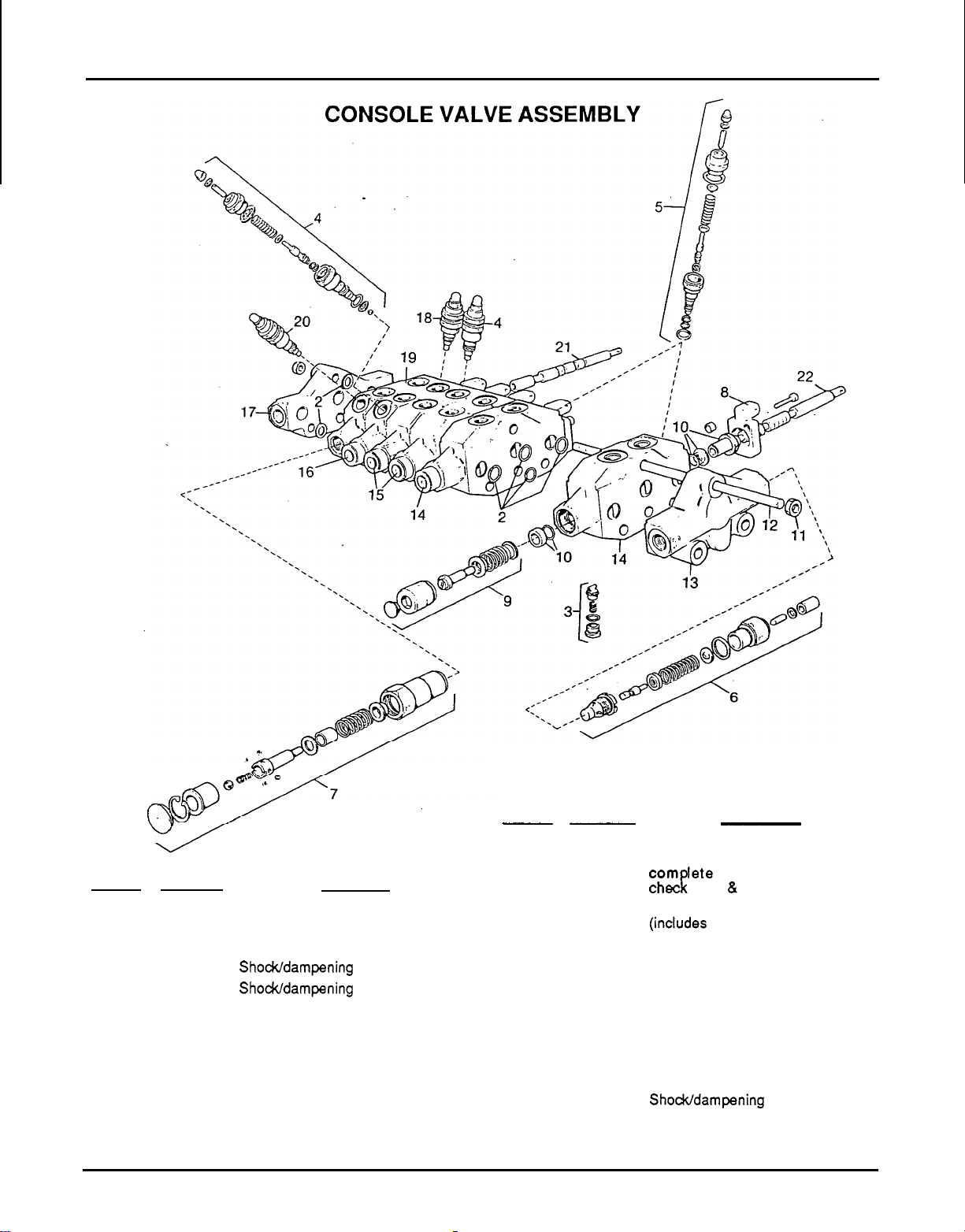
CONSOLE VALVE ASSEMBLY
Ref
No.
1
2
3
4
5
6
7
8
9
10
11
12
No.
Used
1
1
6
2
2
1
1
6
5
6
6
3
Descrition
Console
valve
Section seal repair kit
Check valve assembly
Shodddampening valve, 2000 psi
Shodddampening valve, 2500 psi
Relief valve assembly
Spool position control assembly
Lever bracket
Spool position control assembly
Spool repair kit
8
mm
x
1.25 mm Pitch hex nut
M8
x
1.25
x
276 Tie rod
1
-
COMPLETE VALVE
Ref
No.
No.
Used Description
13
1
Front
port
inlet section complete
14 2 Dipperstick and bucket segments
com lete (includes body, spool,
chA
valve
&
2500
psi
relief
assy.)
15
2
Stabilizer segment complete
(indudes body, spool
8
check valve)
16 1 Swing segment complete (includes
body,
spool,
check valve
8
two
2000
psi relief assemblies)
17 1
Standard exhaust section
18
1
Shodddampening valve, 3500 psi
19 1
Boom segment complete (includes
body,
spool
with
float
position, check
valve, 3500 psi
8
2500 psi relief
assemblies)
20 1
Shodddampening valve, 2500 psi
21 1
Spool (used on boom segment only)
22
5
Spool
66
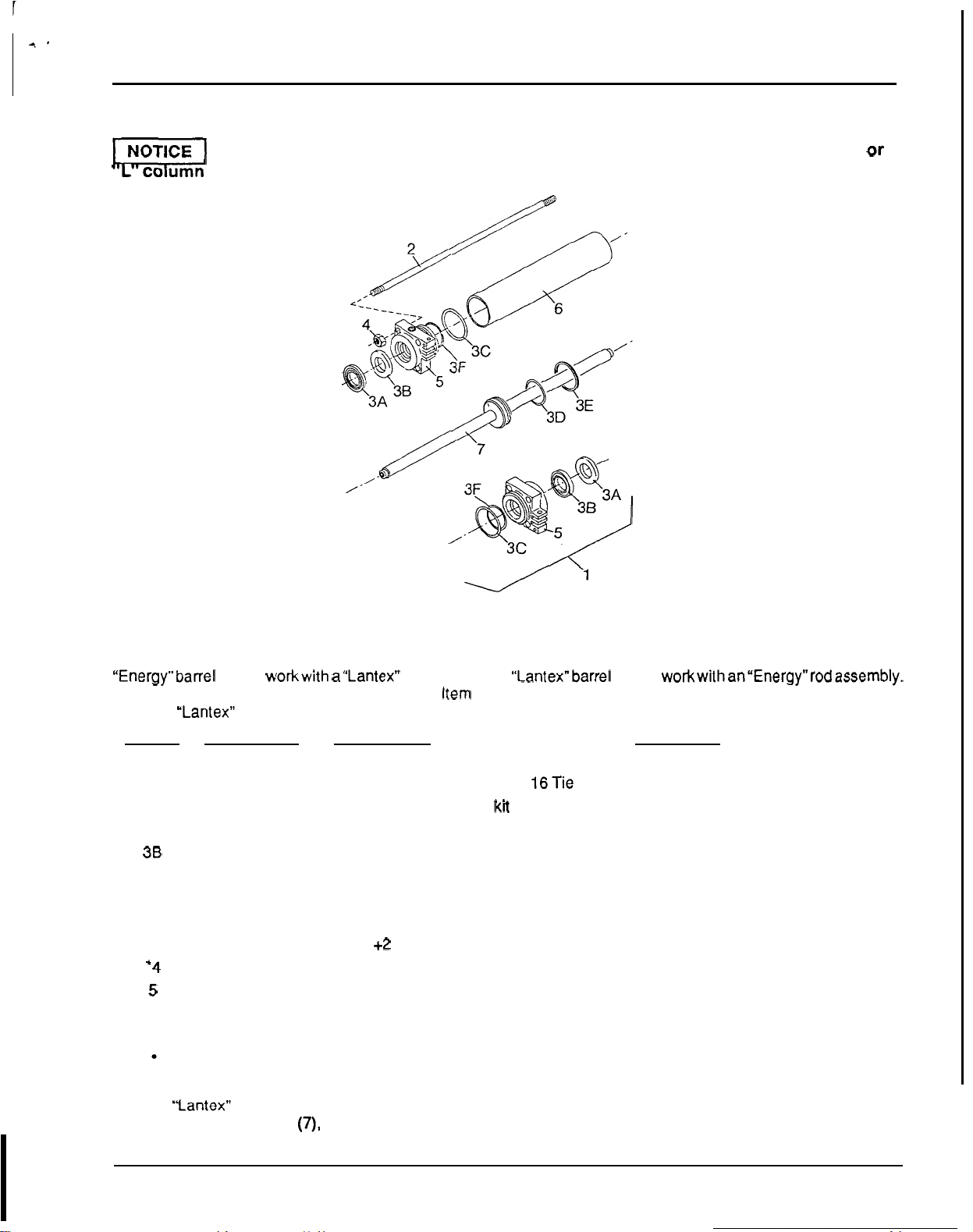
SWING CYLINDER
SWING CYLINDER
TI
Be sure to make proper manufacturer identification, then refer to either the
"
E
"
Or
co
umn when ordering parts.
Swing cylinders were obtained from two suppliers.
All
itemsexcept barrel
(6)
and rod assembly
(7)
are interchangeable
between cylinders. When ordering either
of
these items, check manufacturer identification.
"
Energy
"
barrels have an
"
E
"
stamped into the barrel.
"
Lantex" barrels will either have an
"
L
"
stamped in the barrel or will be unmarked. An
"Energy"barre1 will not workwith a"Lantex" rod assembly.
A
"Lantex"barre1 will not
workwithan"Energy"rodassemb1y.
The seal kit contains repairs
for
both cylinders. Item
(3F)
back
-
up ring is not used on item
(5)
piston rod guide with
the word
"Lantex" in the casting.
Ref
No.
No.
Used
"
E
"
No.
Used
"
L
"
1
1
1
2
4
4
3
1 1
.
3A
2
2
38
2 2
3c
2 2
3D
1 1
3E
1 1
3F
2
+2
*4
8 8
5
2 2
6
1
++
7
1
++
Obtain Locally
+
(3F
Not)
used on Lantex
Description
Hydraulic swing cylinder complete
7/16
NF
x
16Tie rod
Seal
kit
(contains
3A
thru 3F)
Rod wiper
Rod
seal
Gland static seal
O
-
ring
Piston seal
Back
-
up ring
7/16
NF
Hex nut
Piston rod guide
Barrel
Rod
assembly
++
"Lantex" barrel and rod assembly are no longer available.
If
you have a
"
Lantex
"
barrel and need to order
either item
(6)
or
(7),
replace both barrel
(6)
and rod assembly
(7)
with
"
Energy
"
parts.
67
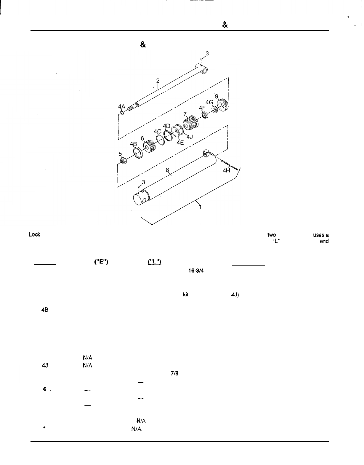
BOOM
&
DIPPERSTICK CYLINDER
-2
.
-1
BOOM
&
DIPPERSTICK CYLINDER
LO&
Wire or Threaded Plug
Style
Cylinder Cylinders used in the same application are provided from
two
suppliers. One
uses
a
lock wire and one uses a threaded plug for locking devices.
Lock
wire cylinders can be identified by the
"L"
stamped on butt end
of
the
cylinder. All threaded plug cylinders have an
"
E
"
stamped on the butt end
of
the cylinder.
Be sure to make proper
manufacturer identification and order repair
parts
from correct column.
Ref
No.
No.
Used
(**E')
No.
Used
('I")
Description
1 1
1 2
-
1/2
x
16-314
Hydraulic cylinder
2
1
1
Rod
assembly
3
2
2 1/4
-
28
Taper thread grease fitting
4
1
1
Seal
ka
(contains
4A
thru
4J)
4A
1
1
Rod static seal
48 NIA
1
Wear strip
4D 1
1
Piston seal
4E
1
1
Gland static seal
4F
1
1
Rod
seal
4G
1
1
Rod wiper
4H
NIA
1
Lock
wire
5
1
1
7/8
NF Self
-
lock hex nut
6
1
-
Piston
6.
-
1
Piston
7
1
-
Gland
7
1
Gland
8
1 1
Barrel
assy.
(Not sold separately)
9
1
N/A Threaded retainer
Obtain Locally N/A
-
Not Applicable
4c
1
1
O
-
ring
4J
N/A
1
Back
-
up washer
-
68
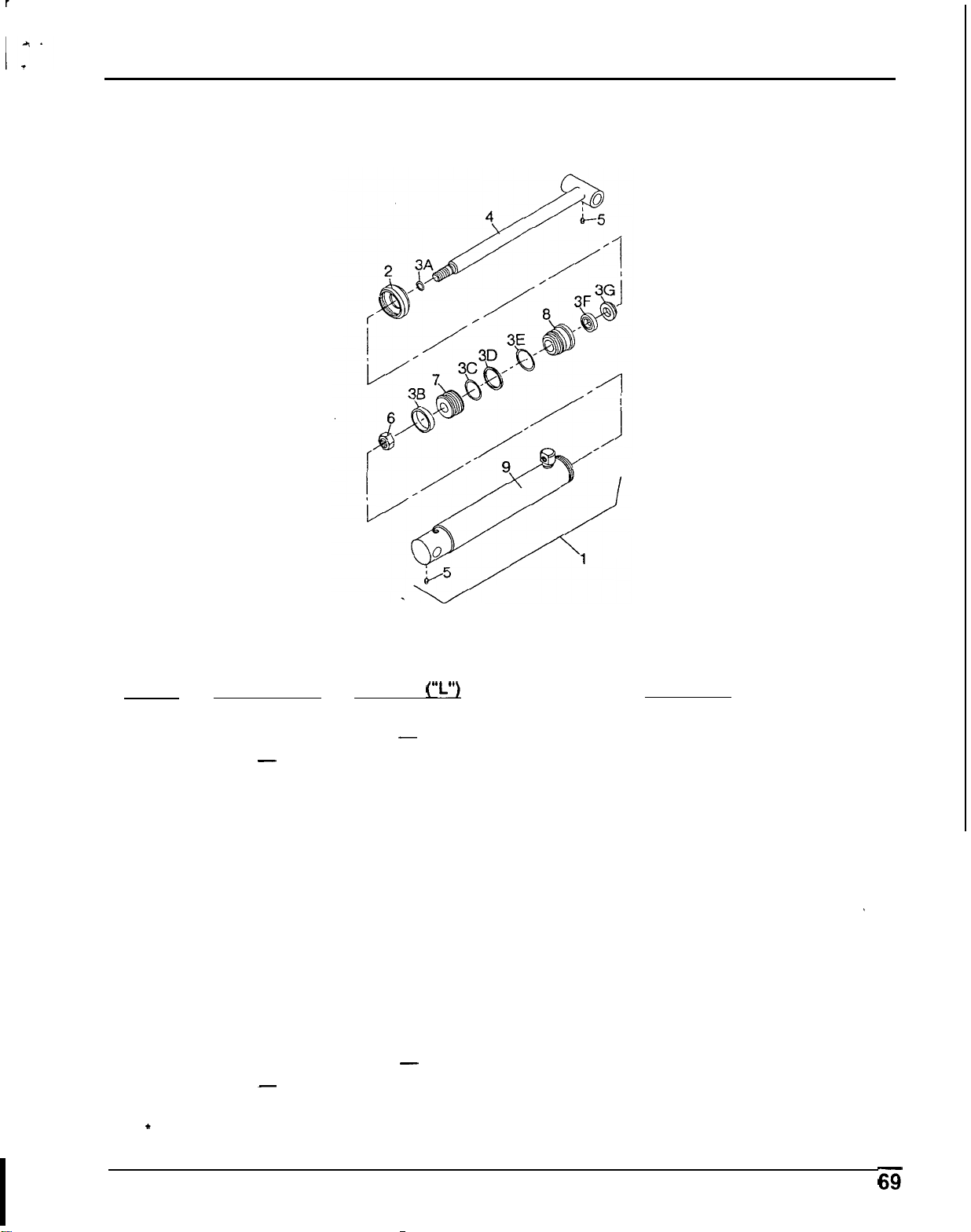
STABILIZER CYLINDER
STABILIZER CYLINDER
Ref
No.
1
2
2
3
3A
3B
3c
3D
3E
3F
3G
4
'5
6
7
8
8
9
No.
Used
(
"
E')
1
1
-
1
2
2
2
1
1
2
1
1
2
1
1
1
-
1
No.
Used
("L")
1
-
1
1
2
2
2
1
1
2
1
1
2
1
1
-
1
1
Description
2
x
14
-
1/2
Hydraulic cylinder assy.
Collar
Collar
Seal
kit
(contains 3A thru 3G)
Rod static seal
Wear ring
O
-
ring
Piston seal
Gland static seal
Rod seal
Rod wiper
Rod assy.
1/4
-
28 Taper greese fitting
7/8
NF
Self
-
lock nut
Piston
Gland
Gland
Barrel assy. (not sold separately)
'
Obtain Locally

BUCKET CYLINDER
BUCKET CYLINDER
Y5
Cylinders are obtained from two suppliers. They may be Identified by an
"
E
"
or
"L"
stamped Into cylinder buff end. Be Sure to
make proper manufacturer identification, then refer to either the
"E"
or
"L"
column when ordering parts.
Ref
No.
No.
Used
("E')
No.
Used
("L")
Description
1
1 1 2
x
16-314 Hydraulic cylinder assy.
2
1
Collar
2
1
-
Collar
3
I
1
Seal kit (contains 3A thru 3H)
-
3A
2
2
Rod static seal
38
2
2
Wear ring
3c
2 2 O
-
ring
3D 1
1
Piston seal
3E
1
1
Gland static seal
3F
2. 2 Rod seal
3G
1
1
Rod wiper
3H
1
+
Back
-
up washer
4
-
1
Rod assy.
4
1
-
Rod assy.
'5
2
2 1/4
-
28 Taper greese fitting
6
1 1 7/8
NF
Self
-
lock nut
7
1
1 Piston
8
1
Gland
8
1
-
Gland
-
9
1
1
Barrel assy. (not sold separately)
1
Obtain Locally
+
Not used on Lantex Cylinders

I+
WARRANTY SERVICE
WARRANTY SERVICE
Your satisfaction and goodwill are important to your dealer and to us. All Honda warranty details are
explained in the Distributor’s Limited Warranty. Normally, any problems concerning the product will be
handled by your dealer’s service department. If you have a warranty problem that has not been handled
to your satisfaction, we suggest you take the following action:
Discuss your problem with a member of dealership management. Often complaints can
be
quickly
resolved at that level. If the problem has already been reviewed with the Service Manager, contact the
Owner
of
the dealership
or
the General Manager.
If
your problem still has not been resolved to your satisfaction, contact the Power Equipment Customer
Service Department of American Honda Motor
Co.,
Inc:
American Honda Motor
Co.,
Inc.
Power Equipment Division
P.O.
Box
100021
Duiuth, Georgia 30136
-
9421
Telephone: (404) 497
-
6400
We will need the following in order to assist you:
-
Your name, address, and telephone number
-
Product model and serial number
-
Date of purchase
-
Dealer name and address
-
Nature of the problem
After reviewing all the facts involved, you will be advised of what action can be taken. Please bear in
mind that your problem will likely be resolved at the dealership, using the dealer’s facilities, equipment,
and personnel,
so
it is very important that your initial contact be with the dealer.
Your purchase of a Honda product is greatly appreciated by both your dealer and American Honda
Motor Company. We want
to
assist you in every way possible to assure your satisfaction with your
purchase.