

Operator’s Manual
www.mechmaxx.com
WARRANTY


TABLE OF CONTENTS
TABLE OF CONTENTS
PREFACE
1
GENERAL COMMENTS
BEFORE OPERATION
SAFETY ALERT SYMBOL
2
2
2
WARNING SIGNS IN THIS MANUAL
3
GENERAL SAFETY PRECAUTIONS
3
EQUIPMENT SAFETY PRECAUTIONS
6
GENERAL INFORMATION
7
SAFETY DECALS
7
BEARING LUBRICATION
16
BEARING LUBRICATION GUIDE BASED ON
ENVIRONMENTAL CONDITIONS
16
ROPS SYSTEM
11
TRACTOR HYDRAULIC SYSTEM
11
TIRE INFLATION
11
WHEEL TREAD SETTINGS
11
BACKHOE OPERATION
11
PRECAUTIONARY NOTES
11
IMPORTANT:
11
INITIAL BACKHOE OPERATION
12
COLD WEATHER OPERATION
12
SWING LOCK AND BOOM LOCK
13
BACKHOE REMOVAL
14
BACKHOE MOUNTING
14
TORQUE SPECIFICATIONS
16
BACKHOE SPECIFICATIONS
8
INTRODUCTION
10
BACKHOE COMPONENTS.
10
IMPORTANT:
10
WARRANTY REGISTRATION
10
SERIAL NUMBER
10
2
SAFETY STATEMENTS
3
DECALS
7
8
15
SPECIFICATIONS
LUBRICATION AND MAINTENANCE
18
PARTS DIAGRAM
19
PARTS LIST
11
TRACTOR PREPARATION
1
www.mechmaxx.com
TABLE OF CONTENTS

2
www.mechmaxx.com
GENERAL COMMENTS
PREFACE
PREFACE
Congratulations on the purchase of your new product!
This product was carefully designed and manufactured to
give you many years of dependable service. Only minor
maintenance(such as cleaning and lubricating) is required
to keep it in top working condition. Be sure to observe all
maintenance procedures and safety precautions in this
manual and on any safety decals located on the product
and on any equipment on which the attachment is mount-
ed.
This manual has been designed to help you do a better,
safer job. Read this manual carefully and become familiar
with its contents.
NOTE: The illustrations and data used in this manual were
current(according to the information available to us) at
the time of printing,however,we reserve the right to
redesign and change the attachment as may be neces-
sary without notification
The primary responsibility for safety with this equipment
falls to the operator.Make sure. The equipment is operat-
ed only by trained individuals that have read and under-
stand this manual.If there is any portion of this manual or
function you do not understand, contact your local autho-
rized dealer or the manufacturer to obtain further assis-
tance. Keep this manual available for reference. Provide
the manual to any new owners and/or operators.
Use only manufacturer replacement parts.Substitute
parts may not meet the required standards. Record the
model and serial number of your unit on the cover of this
manual. The parts department needs this information to
insure that you receive the correct parts.
BEFORE OPERATION
SAFETY ALERT SYMBOL
Never let anyone operate this unit without
reading the “Safety Precautions” and “
operating Instructions”sections of
manual. Always choose hard, level ground
to park the vehicle on and set the brake so
the unit cannot roll.
Unless noted otherwise, right and left
sides are determined from the operator’s
control positioning when facing the
attachment.

3
www.mechmaxx.com
WARNING SIGNS IN THIS MANUAL
DANGER
SAFETY STATEMENTS
SAFETY
The following warning signs in this manual draw addition-
al attention to items of importance for the safe and
correct operation of the rotavator.
GENERAL SAFETY PRECAUTIONS
READ MANUAL PRIOR TO INSTALLATION
Improper installation,operation,or main-
tenance of this equipment could result in
serious injury or death.Operation and
maintenance personnel should read this
manual,as well as all manuals related to
this equipment and the Tractor thoroughly
before beginning installation,operation,or
maintenance. FOLLOW ALL SAFETY
INSTRUCTIONS IN THIS MANUAL
READ AND UNDERSTAND ALL SAFETY
STATEMENTS
Read all safety decals and safety state-
ments in all manuals prior to operating or
working on this equipment.Know and obey
all OSHA regulations,local laws, and other
professional guidelines for your opera-
tion.Know and follow good work practices
when assembling,maintaining,repair-
ing,removing,or operating this equipment.
KNOW YOUR EQUIPMENT
know your equipment’s capabilities,
dimensions and operations before operat-
ing.
Visually inspect your equipment before
you start, and never operate equipment
that is not in proper working order with
safety devices intacts.check all hardware
to ensure it is tight.Make certain that all
locking pins,latches,and connection
devices are properly installed and
secured. Remove and replace any dam-
aged,fatigued,or excessively worn parts.-
Make certain all safety decals are in place
and are legible. Keep decals clean,and
replace them if they become worn and
hard to read
PROTECT AGAINST FLYING DEBRIS
Always wear proper safety glasses,
goggles or a face shield when driving pins
in or out, or when any operation causes
dust,flying debris,or any other hazardous
material.
WARNING
CAUTION
NOTICE
THIS SIGNAL WORD IS USED WHERE SERI-
OUS INJURY OR DEATH WILL RESULT IF
THE INSTRUCTIONS ARE NOT FOLLOWED
PROPERLY
THIS SIGNAL WORD IS USED WHERE SERI-
OUS INJURY OR DEATH COULD RESULT IF
THE INSTRUCTIONS ARE NOT FOLLOWED
PROPERLY
THIS SIGNAL WORD IS USED WHERE
MINOR INJURY COULD RESULT IF THE
INSTRUCTIONS ARE NOT FOLLOWED
PROPERLY
NOTICE INDICATES A PROPERTY
DAMAGE MESSAGE
4
www.mechmaxx.com
SAFETY
LOWER OR SUPPORT RAISED EQUIPMENT
Do not work under raised booms without
supporting them. Do not use support
material made of concrete blocks,logs,-
buckets,barrels or any other material that
could suddenly collapse or shift posi-
tions.Make sure support materials is
solid, not decayed,warped,twisted,or
tapered. Lower booms to ground level or
onto blocks. Lower booms and attach-
ments to the ground before leaving the
cab or operator’s station.
DO NOT MODIFY MACHINE OR ATTACH-
MENTS
Modifications may weaken the integrity of
the attachment and may impair the func-
tion,safety,life and performance of the
attachment. When making repairs,use
only manufacturer’s genuine parts,follow-
ing authorized instructions. Other parts
may be substandard in fit and quality.
Never modify any ROPS(Roll over Protec-
tion Structure) or FOPS(Falling object
Protective Structure) equipment or
device. Any modifications must be autho-
rized in writing by the manufacturer.
SAFELY MAINTAIN AND REPAIR EQUIP-
MENT.
Do not wear loose clothing, or any acces-
sories that can catch in moving parts.
• If you have long hair, cover or secure it
so that it does not become entangled in
the equipment.
• Work on a level surface in a well-lit area.
• Use properly grounded electrical outlets
and tools.
• Use the correct tool for the job at hand.
Make sure they are in good condition for
the task required.
• Wear the protective equipment specified
by the tool manufacturer.
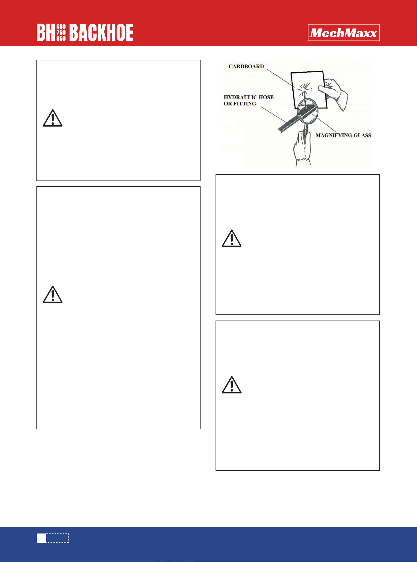
USE CARE WITH HYDRAULIC FLUID PRES-
SURE
Hydraulic fluid under pressure can pene-
trate the skin and cause serious injury or
death. Hydraulic leaks under pressure
may not be visible. Before connecting or
disconnecting hydraulic hoses,read and
Tractors operator’s manual for detailed
instruction on connecting and disconnect-
ing hydraulic hoses or fittings
• Keep unprotected body parts, such as
face,eyes,and arms as far away as possi-
ble from a suspected leak. Flesh injected
with hydraulic fluid may develop gangrene
or other permanent disabilities.
• If injured by injected fluid, see a doctor
at once. If your doctor is not familiar with
this type of injury, ask him to research
immediately to determine proper treat-
ment.
• Wear safety glasses, protective clothing,
and use a sound piece of cardboard or
wood when researching for hydraulic
leaks.DO NOT USE YOUR HANDS! SEE
ILLUSTRATION.

5
www.mechmaxx.com
SAFETY
KNOW WHERE UTILITIES ARE
Observe overhead electrical and other
utility lines. Be sure equipment will clear
them. When digging, call your local
utilities for location of buried utility
lines,gas,water,and sewer, as well as any
other hazard you may encounter.
END OF LIFE DISPOSAL
At the completion of the useful life of the
unit, drain all fluids and dismantle by
separating the different materials(rubber,
steel,plastic,etc).Follow all federal, state
and local regulations for recycling and
disposal of the fluid and components
OPERATING THE ATTACHMENT
• Do not exceed the lifting capacity of your
Tractor.
•Operate only from the operator’s station.
• When operating on slopes, drive up and
down, not across. Avoid steep hillside
operation,which could cause the Tractor
to overturn.
• Reduce speed when driving over rough
terrain, on a slope, or turning, to avoid
overturning the vehicle.
• An operator must not use drugs or alco-
hol, which can change his or her alertess
or coordination. An operator taking
prescription or over-the-counter drugs
should seek medical advice on whether or
not he or she can safely operate equip-
ment.
REMOVE PAINT BEFORE WELDING OR
HEATING
Hazardous fumes/dust can be generated
when painted heated by welding, solder-
ing or using a torch. Do all work outside or
in a well ventilated area and dispose of
paint and solvent properly. Remove paint
before welding or heating.
When sanding or grinding paint, avoid
breathing the dust, Wear an approved
respirator. If you use solvent or paint
stripper, remove stripper with soap and
water before welding. Remove solvent or
paint stripper contains and other flamma-
ble material from area. Allow fumes to
disperse at least 15 minutes before weld-
ing or heating.
EXPOSURE TO RESPIRABLE CRYSTAL-
LINE SILICA DUST ALONG WITH OTHER
HAZARDOUS DUSTS MAY CAUSE SERI-
OUS OR FATAL RESPIRATORY DISEASE.
It is recommended to use dust suppre-
sion,dust collection and if necessary
personal protective equipment during the
operation of any attachment that may
cause high levels of dust.
SAFELY OPERATE EQUIPMENT
Do not operate equipment until you are
completely trained by a qualified operator
in how to use the controls.Know its capa-
bilities,dimensions,and all safety require-
ments. See your machine’s manual for
these instructions.
• Keep all step plates, grab bars,ped-
als,and controls free of dirt, grease,
debris, and oil.
• Never allow anyone to be around the
equipment when it is operating.
• Do not allow riders on the attachment or
the Tractor.
• Do not operate the equipment from
anywhere other than the correct operators
position.
• Never leave equipment unattended with
the Engine running or with this attachment
in a raised position.
• Do not alter or remove any safety feature
from the Tractor or this attachment.
• Know your work site safety rules as well
as traffic rules and the flow. When in
doubt on any safety issue, contact your
supervisor or safety coordinator for an
explanation

6
www.mechmaxx.com
SAFETY
EQUIPMENT SAFETY PRECAUTIONS
OPERATING THE ATTACHMENT
• Never heap or load heavy material where
the combined weight of the bucket and
material could exceed the rated lifting
capacity of the backhoe.
• Be sure the load does not stick out too
far in front of the bucket. A light load
sticking out too far can have the same
tipping effect as a heavy load carried in
close.
• If the load appears to be unstable, lower
the load, and repositioning the load to
attain stability.
• When using the Backhoe, lift the load
slightly and make sure that the load is
secure. If the load appears to be an unsta-
ble, lower the load, and reposition the load
to attain full stability.
• Before Exiting the Tractor, lower the
attachment to the ground, turn off the
Tractor’s Engine, remove the key and
apply the brakes.
TRANSPORTING THE ATTACHMENT
• Travel only with the attachment in a safe
transport position to prevent uncontrolled
movement. Drive slowly over rough
ground and on slopes.
• When transporting on a trailer: secure
attachment at recommended tie down
locations using tie down accessories that
are capable of maintaining attachment
stability.
• When driving on public roads use safety
lights,reflectors,Slow moving vehicle
signs etc., to prevent accidents. Check
local government regulations that may
affect you.
• Do not dive close to ditches,excava-
tors,etc,.cave in could result.
• Do not smoke when refueling the Trac-
tor. Allow room in the fuel tank for expan-
sion. Wipe up any spilled fuel. Secure cap
tightly when done.
MAINTAINING THE ATTACHMENT
• Before performing maintenance, lower
the attachment to the ground, apply the
brakes, turn off the engine, and remove
the key.
• Never perform any work on the attach-
ment unless you authorized and qualified
to do so.Always read the operator service
manual’s before any repair is made. After
completing maintenance or repair, check
for correct functioning of the attachment.
If not functioning properly, always tag" DO
NOT OPERATE" until all problems are
corrected.
• Worn, damaged or ,illegible safety
decals must be replaced. New safety
decals can be ordered from Dealer or
manufacturer.
• Never make hydraulic repairs while the
system is under pressure. Serious
personal injury or death could result.
• Never work under a raised attachment.
7
www.mechmaxx.com
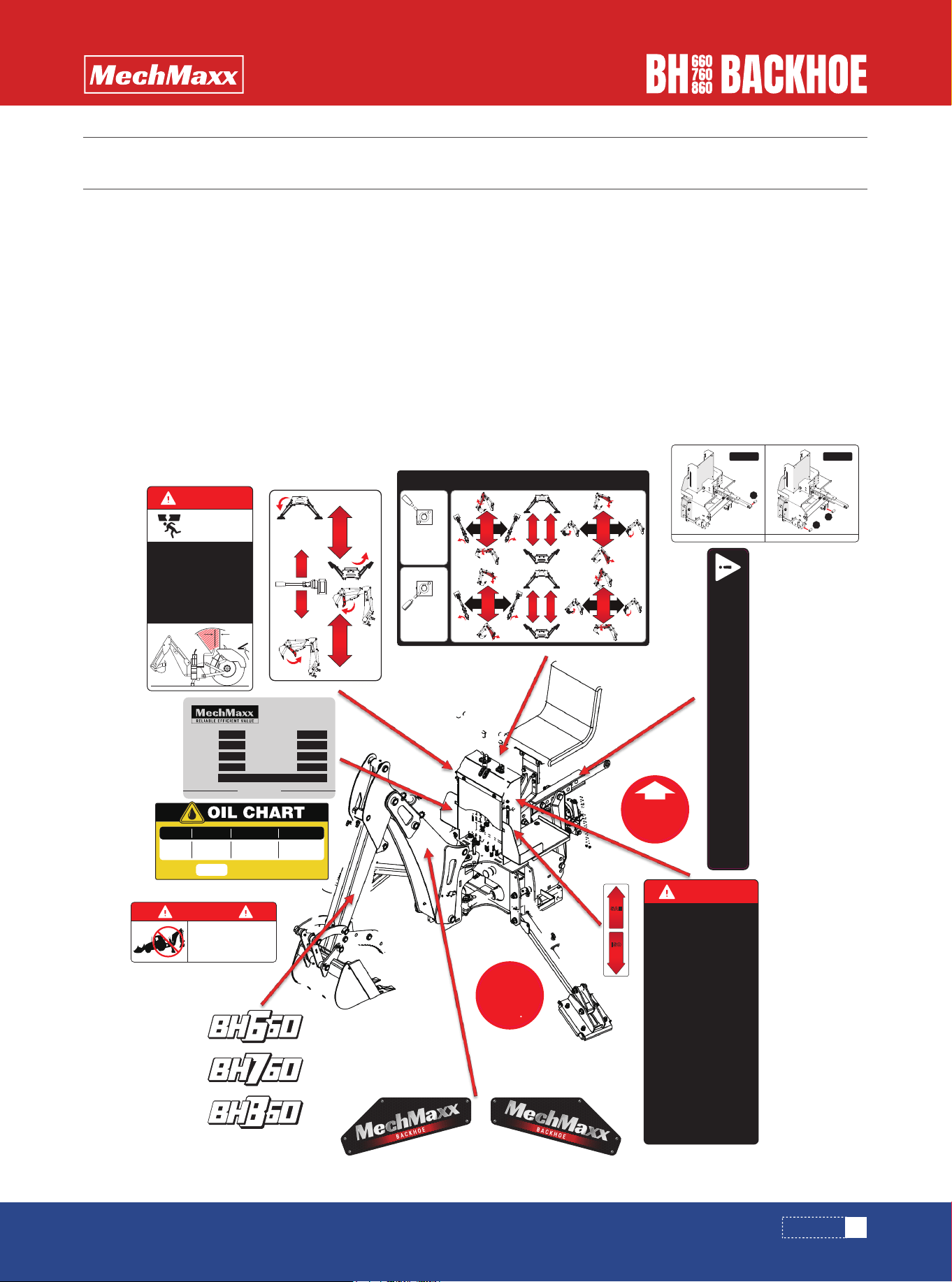
DECALS
DECALS
The following diagrams show the location of all the decals on your attachment.
The decals are identified by their parts numbers,with the reductions of the actual decals shown on the following
pages.Use this information to order replacements for lost or damaged decals. Be sure you understand all decals before
operating the attachment. They contain information you need to know for attachment safety(See decal explanations.)
IMPORTANT: Keep all safety decals clean and legible. Replace all missing, or damaged safety decals. When replacing
parts with safety decals attached, the safety decals must also be replaced.
REPLACING SAFETY DECALS.:Clean the area of application with nonflammable solvent, then wash the same area with
soap and water. Allow the surface to dry. Remove the backing from the safety decal, exposing the adhesive surface. Apply
the safety decal to the position shown in the diagram, and smooth out any bubbles.
GENERAL INFORMATION
SAFETY DECALS
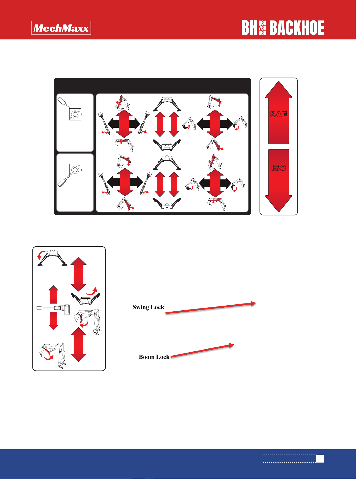
BACKHOE CONTROL PATTERN
SAE
CONTROL
PATTERN
SAE
CONTROL
PATTERN
SWING
LEFT
SWING
RIGHT
DIPPER
OUT
DIPPER
IN
SWING
LEFT
SWING
RIGHT
DIPPER
OUT
DIPPER
IN
BUCKET
CURL
BUCKET
DUMP
BOOM
DOWN
BOOM
UP
BUCKET
CURL
BUCKET
DUMP
BOOM
DOWN
BOOM
UP
L R
L R
WARNING!
Disengage draft control (if equipped). Do not raise 3-point
hitch. Do not lift rear tire off ground with either support
legs or boom. Damage may occur to your tractor or
top link. (See owner's manual for more information)
SAE
CONTROL
PATTERN
ISO
CONTROL
PATTERN
RIGHT
SUPPORT LEG
THUMB
R
R
ISO
GRADE
32
46
68
10W
20
20W
30°-80° F
40°-100° F
50°-100° F
ISO 46 (also referred to as AW 46) is a good all
around grade of hydraulic oil suitable for most
situations.
25°-145° F
30°-160° F
35°-185° F
SAE GRADE
EQUIVALENT
AIR
TEMPERATURE
OPERATING
TEMPERATURE
4.1Gal/15.5L
Hydraulic Tank:
DANGER
1. Always fully lower the tractor's 3-point hitch
control when the backhoe is mounted on the tractor.
2. Do not raise the 3-point hitch once the backhoe is
attached to your tractor.
3. Do not raise the rear of the tractor off the ground
using the backhoe's stabilizer legs.
4. Do not raise the backhoe or the rear of the tractor
off the ground by pushing the bucket downward.
INSTALL
THIS END UP
& FACING
OUT
540
max
DANGER
READ OPERATOR'S MANUAL BEFORE USING
BACKHOE.
OPERATE BACKHOE CONTROL ONLY FROM
NORMAL BACKHOE OPERATOR'S SEAT
POSITION.
OPERATE ONLY WITH STABILIZERS DOWN
AND ON FIRM FOOTING. AVOID DIGGING IN
AREA OF STABILIZER PADS. STAY AWAY FROM
STEEP AREAS OR EXCAVATION BANKS THAT
COULD GIVE WAY.
CHECK THE OPERATING AREA TO BE DUG
FOR ANY POSSIBLE OVERHEAD OR
UNDERGROUND LINES SUCH AS ELECTRIC,
GAS, OIL, WATER, ETC. EXTREME CAUTION
MUST BE EXCERCISED IN THESE AREAS
WHERE PRESENT. CONSULT LOCAL UTILITIES
BEFORE DIGGING.
KEEP BYSTANDERS AWAY FROM MAXIMUM
SWING AREA REACHED AND STABILIZERS.
KEEP ALL GUARDS IN PLACE.
INSPECT BACKHOE DAILY FOR LOOSENED,
BENT, OR BROKEN PARTS.
ENGAGE SAFETY LOCKS BEFORE
TRANSPORTING OR SERVICING BACKHOE.
BE SURE TRACTOR IS WEIGHTED TO
PROVIDE AT LEAST 20% OF TOTAL WEIGHT
ON THE FRONT WHEELS WITH BACKHOE IN
TRANSPORT POSITION.
DO NOT USE TRACTOR WITH HYDRAULIC
SYSTEMS THAT EXCEED 8 GPM FLOWRATE
OR 2500 PSI OPERATING PRESSURE.
HIGH PRESSURE HYDRAULIC OIL LEAKS CAN
PENETRATE SKIN, CAUSING SEVERE
INJURIES OR EVEN DEATH. USE CARDBOARD,
NOT HANDS, TO CHECK FOR LEAKS.
OPERATE PTO AT 540 RPM. DO NOT EXCEED.
FOR 3-POINT RIGID MOUNT BACKHOES ONLY.
1050 LB LIFT FORCE REQUIRED AT 24"
BEHIND LIFT POINT.
IMPROPER TRANSPORTING METHODS CAN
CAUSE SERIOUS DAMAGE TO THE TRACTOR.
(READ OPERATOR'S MANUAL)
1.
2.
3.
4.
5.
6.
7.
8.
9.
10.
11.
12.
13.
14.
DANGER
CRUSHING
HAZARD
DO NOT OPERATE 3-POINT RIGID MOUNT
BACKHOE ATTACHMENT UNLESS HITCH
AND STABILIZER BARS ARE INSTALLED
PROPERLY. FAILURE TO DO SO MAY
RESULT IN SERIOUS INJURY OR DEATH
BY BACKHOE BEING THRUSTED UPWARD
BY DIGGING FORCESCRUSHING THE
OPERATOR.
OPERATOR'S AREA (SHADED AREA OF 40"
RADIUS FROM SEAT TO 10" BEHIND SEAT)
MUST BE FREE FROM ALL
OBSTRUCTIONS.
40” MIN
RADIUS
10” MIN
Only the upper suspension requires 1 top link bushing. Only two lower suspensions require 2 lift arm bushings.
1
2
2
CAT
I
CAT
II
www.mechmaxx.com
Year Of MFG:
PTO Speed:
Hitch Type:
Digging Depth:
Serial No.:
Model:
Weight With Bucket:
Min HP:
Min Tractor Weight:
BACKHOE
8
www.mechmaxx.com
BACKHOE SPECIFICATIONS
SPECIFICATIONS
SPECIFICATIONS
Specifications and design are subject to change without prior notice.

9
www.mechmaxx.com
About compatibility with the tractor, ensure the tractor’s HP and 3-point hitch fit the backhoe, and
the tractor meets the minimum weight for safe operation. If the tractor is too light, add front ballast
to improve balance and reduce tipping risks. Also, consider the tractor’s operating conditions,
such as speed and slope. Above all, always prioritize safety during operation.
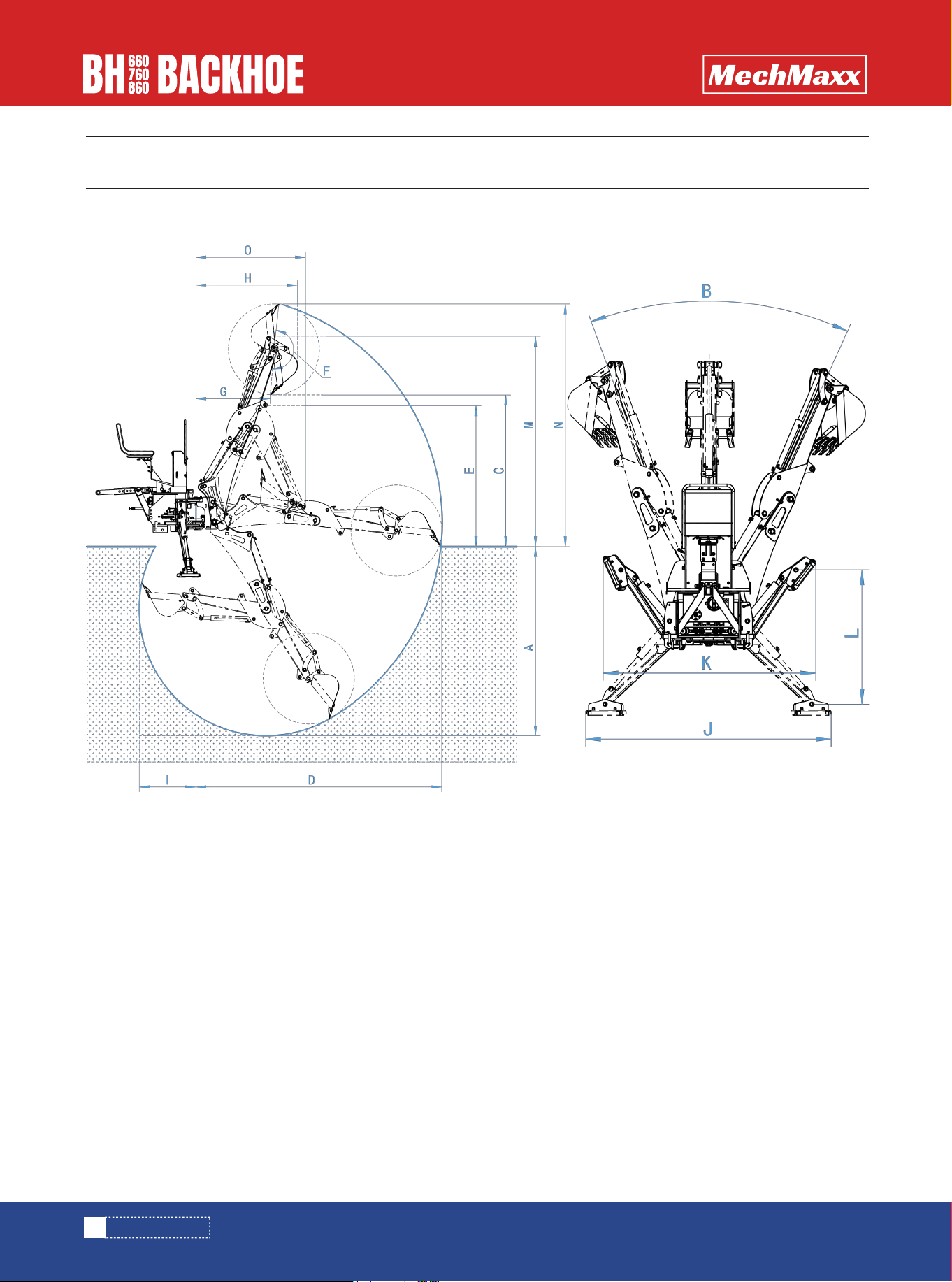
SPECIFICATIONS
Max. Digging Depth
Digging Depth (two foot flat bottom)
Swing Arc
Loading Height (bucket at 60 °)
Reach from Center Line of Swing Pivot
Transport Height (maximum)
Bucket Rotation
Loading Reach (bucket at 60 °)
Transport Overhang
Undercut
Stabilizer Spread (down position)
Stabilizer Spread (up position)
Stabilizer Spread (lifting height)
Transportation Height (maximum altitude)
Loading Height (bucket at 180 °)
Transport Overhang (maximum)
Bucket Cylinder Digging Force
Dipper stick Cylinder Digging Force
Hydraulic Volume Requirements
Hydraulic Pressure Requirements
Hydraulic Tank Capacity
Hydraulic Type Recommended
Self-contained Hydraulic Pump & Tank
7 ft
6 ft 6 in
180 Degrees
4 ft 9 in
9 ft 1 in
5 ft 2 in
180 Degrees
3 ft 8 in
4 ft 9 in
1 ft 6 in
6 ft 7 in
5 ft 9 in
3 ft 8 in
7 ft 2 in
8 ft 4 in
4 ft 2 in
2840 lbs
2005 lbs
4 to 5 GPM
2250psi
4.1 US Gal (15.5L)
AW 46
Included
8 ft
7 ft 6 in
180 Degrees
6 ft
9 ft 9 in
5 ft 7 in
180 Degrees
3 ft 7 in
4 ft 3 in
2 ft 3 in
6 ft 7 in
5 ft 9 in
3 ft 8 in
8 ft 4 in
9 ft 7 in
4 ft 5 in
2840 lbs
2005 lbs
5 to 6 GPM
2250psi
4.1 US Gal (15.5L)
AW 46
Included
9 ft
8 ft 6 in
180 Degrees
6 ft 1in
10 ft 8 in
6 ft 2 in
180 Degrees
4 ft 3 in
5 ft 4 in
2 ft 2 in
6 ft 7 in
5 ft 9 in
3 ft 8 in
8 ft 9 in
9 ft 10 in
4 ft 5 in
3000 lbs
2500 lbs
5 to 6 GPM
2250psi
4.1 US Gal (15.5L)
AW 46
Included
Model BH660 BH760 BH860
ISO or SAE Switch
Thumb
PTO Connection
Recommended HP
3-Point Hitch
Min Tractor Weight
Included
Mechanical
1-3/8" 6 Spline
15 to 50 HP
CAT I
1500 lbs
Included
Hydraulic
1-3/8" 6 Spline
20 to 100 HP
CAT I & II
2300 lbs
Included
Hydraulic
1-3/8" 6 Spline
Standard Bucket Size 12 in (3 teeth) 15 in (4 teeth) 15 in (4 teeth)
PTO Speed 540 RPM 540 RPM 540 RPM
25 to 100 HP
CAT I & II
3200 lbs
A.
B.
C.
D.
E.
F.
G.
H.
I.
J.
K.
L.
M.
N.
O.

10
www.mechmaxx.com
SPECIFICATIONS
INTRODUCTION.
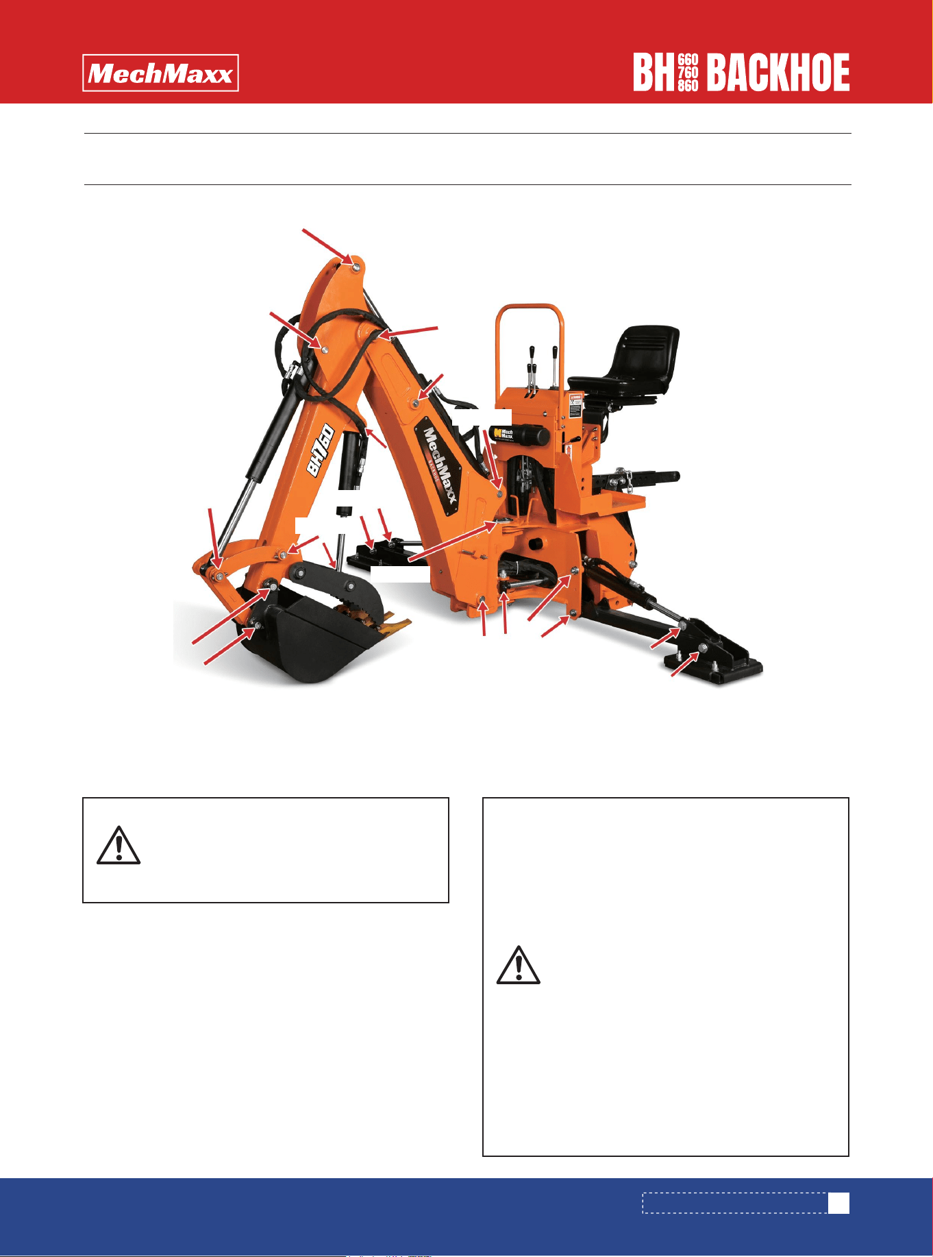
BACKHOE COMPONENTS.
The purpose of this manual is to assist you in maintaining
and operating your backhoe. Read it carefully, it furnishes
information and instructions that will help you achieve
years of dependable performance. Some information may
be general in nature due to unknown and varying condi-
tions. However, through experience and these instruc-
tions, you should be able to develop operating procedures
suitable to your particular situation.
"Right" and "Left" as used throughout this manual are
determined by facing the direction the machine will travel
when in use.
The photos, illustrations and data used in this manual are
current at the time of printing, but due to possible in-line
production changes, your machine may vary slightly in
detail. The manufacturer reserves the right to redesign
the machine as may be necessary without notification.
Terms for backhoe components have some variations
throughout the industry.
IMPORTANT:
Illustrations used in this manual may not show all safety
equipment that is recommended to ensure safe operation
of tractor and backhoe. Refer to the Safety Precautions
section of this manual for information concerning safety.
consult your dealer for further information.
WARRANTY REGISTRATION
The Delivery and Warranty Registration forms must be
filled out and signed to validate your warranty protection.
The items on the form under "I hereby Acknowledge"
should be read and understood. The terms and conditions
of the warranty on this machine are specified in the front
of this manual.
SERIAL NUMBER
The serial number is important information about the
machine and it may be necessary to know it before
obtaining the correct replacement part.
1.Base assembly
2.Steering assembly
3.Left leg assembly
4.Right leg assembly
5.Moving arm assembly
6.Console assembly
7.Seat assembly
8.Base connecting rod assembly
9.The fuel tank assembly
10.PTO pump assembly
11.Bucket Assembly
12.Mechanical/Hydraulic Log Grab Components

TRACTOR PREPARATION
TRACTOR PREPARATION
11
www.mechmaxx.com
ROPS SYSTEM
The tractor must be equipped with an approved ROPS
System to ensure adequate operator's protection.
TRACTOR HYDRAULIC SYSTEM
Tractor operation in a backhoe application significantly
increase demands on the tractor Hydraulic System. Check
the tractor Hydraulic system fluid level daily. Refer to your
tractor Operator's Manual maintenance section for
instructions regarding tractor hydraulic system mainte-
nance.
Adhere to recommendation in your Tractor Operator's
Manual concerning hydraulic fluid and filter specifica-
tions, and change intervals.
-Check below items before operating for your safety.
-Read and understand this manual to avoid accidents.
-Check the hydraulic fitting lines to be correct and set
tightly.
-Maintain and repair (if it is needed) the parts or assem-
blies, check bolts and pins to be sure they are positioned
tightly.
-Check tractor with the tractor operator's manual that it
can prepared for operating.
-Warm up and operate the tractor and backhoe carefully.
Purge any air in the hydraulic lines and cylinders by fully
cycling all cylinders several times.
-Check hydraulic level in the tank. It should be full (Refer
to the Tractor Operator's Manual).
-Do not operate the hydraulics when not seated in the
backhoe operator's seat.
-Keep all assistants out of area of operation.
-Do not operate rapidly.
-Do not allow riders other than the operator to be on the
tractor while operating.
Use tractor engine speed that your experience permits. At
first set PTO RPM of the tractor to slow. Do not use the
boom, dipper stick, swing and stabilizers to lift, push or
pull objects. Use only to maneuver and operate the
bucket.
Practice quickly turning off the engine or stopping the
backhoe immediately in case of an emergency situation.
Do not operate while the rear tractor wheels are off the
ground by stabilizer. It is dangerous to operate the back-
hoe while rear wheels are off the ground.
TIRE INFLATION
Front tires must be maintained at the maximum recom-
mended inflation to maintain normal tire profile with the
added weight of backhoe/material.
Rear tires must be maintained at equal pressure within
the recommended tire inflation range. Unequal rear tire
inflation can prevent backhoe attachment from contact-
ing the ground across its full width.
WHEEL TREAD SETTINGS
Tractor front wheel tread setting must be restricted to
wheel tread spacing recommended in the tractor Opera-
tor's Manual.
BACKHOE OPERATION
PRECAUTIONARY NOTES
IMPORTANT:
Do not exceed the manufacturer's rating
for maximum gross vehicle weight. Refer
to Operator's Manual or ROPS serial plate
provided with tractor.
The tractor/backhoe should only be oper-
ated with all safety equipment properly
installed. Keep assistants or bystanders a
safe distance from the equipment operat-
ing area.
Certain specific conditions may not
permit safe use of backhoe at backhoe
rating or may require more careful
restricted operation at the rated load.
The tractor/backhoe must only be operat-
ed with all safety equipment properly
installed.

Position vehicle so that the backhoe is as near to the pile
as possible and in such a direction as to minimize the
amount of tractor turning required to dump.
Keep the unit clean and perform regular service. Observe
safety messages whenever cleaning, servicing, or
lubricating.
We urge you to follow this advice:
1.Read and understand this manual as well as the Tractor
Operator's Manual.
2. Remember and observe the Safety. Precautions
brought to your attention in this manual, the tractor
manual and on the machinery itself.
3. Use good common sense in the everyday operation of
this unit. Safety recommendations can never be all inclu-
sive and you are responsible for watching out for and
avoiding unsafe conditions.
4. Never exceed the limits of a piece of machinery. If its
ability to do a job or to do so safely is in question, don't try
it.
5. Don't hurry the learning process or take the unit for
granted. Ease into it and become familiar with your new
backhoe and tractor.
Before operating the backhoe, fully raise and lower the
boom, arm, swing and stabilizers two or three times. Then
raise the bucket above the ground and cycle the bucket
cylinders three times. Lower the bucket to the ground.
Check the tractor hydraulic oil and the correct oil level.
Always keep cylinders in a retracted position when the
backhoe is not in use to guard against rust and contami-
nation which may cause damage to the cylinder rods or
hydraulic system. Also, lock the swing and boom while
tractor is moving and storing for an extended period of
time.
For smooth operation in cold weather, let the tractor
warm up. Slowly cycle all of the cylinders several times to
warm the oil in the hydraulic system. The backhoe may
operate erratically until the hydraulic oil has warmed to
operating temperatures.
INITIAL BACKHOE OPERATION
COLD WEATHER OPERATION
When lowering a heavy load, ease it down-
ward slowly. Never drop a loaded attach-
ment and "catch it hydraulically". Stop-
ping a load after it has gained downward
momentum places undue strain on the
unit and may cause unnecessary damage
to the backhoe or tractor or even worse,
personal injury.
Before leaving the machine, stop the
engine, remove the key, place all controls
in neutral, and either set the parking brake
or place tractor in park as equipped.
Operate controls only when seated in the
operator's seat.
Before disconnecting hydraulic lines,
relieve all hydraulic pressure. Escaping
hydraulic oil under pressure can have
sufficient force to penetrate the skin
causing serious personal injury. If injured
by escaping hydraulic oil seek medical
attention immediately.
Do not operate the backhoe if the fittings
are leaking or if the hoses are damaged. A
sudden line burst would cause the main-
frame to drop suddenly,causing damage
to the tractor or backhoe or injury to
personnel.
12
www.mechmaxx.com
TRACTOR PREPARATION
TRACTOR PREPARATION
13
www.mechmaxx.com
Do not dig near the stabilizers to avoid possible accident.
Do not lift the tractor rear wheels by stabilizers. Also, be sure the stabilizers are seated on hard ground to support. The
backhoe/tractor.
Your backhoe is one of kind in the industry. MechMaxx backhoe allows the user to switch between ISO and SAE control
positions.
When transporting or dismounting backhoe, you must lock the backhoe's swing and boom. Position boom straight back
and drop pin through holes in swing frame and boom. When not in use, store pin in hole provided on swing frame and boom.
Observe the following safety warnings when working with your new backhoe/tractor.
MechMaxx backhoe with hydraulic thumb ,
This label indicates which way to push the lever to activate hydraulics to the thumb or the
stabilizer leg, respectively.
SWING LOCK AND BOOM LOCK
SAE
CONTROL
PATTERN
ISO
CONTROL
PATTERN
BACKHOE CONTROL PATTERN
SAE
CONTROL
PATTERN
,S2
CONTROL
PATTERN
6:,1*
/()7
6:,1*
5,*+7
',33(5
287
',33(5
,1
6:,1*
/()7
6:,1*
5,*+7
',33(5
287
',33(5
,1
%8&.(7
&85/
%8&.(7
'803
%220
'2:1
%220
83
%8&.(7
&85/
%8&.(7
'803
%220
'2:1
%220
83
L R
L R
RIGHT
SUPPORT LEG
THUMB
R
R
14
www.mechmaxx.com
TRACTOR PREPARATION
STEP 1.
Move the tractor to backhoe storage place.
STEP 2.
Use the inner two levers to lower the stabilizers until they
contact to the ground. Use the boom and dipperstick
control lever to raise the boom & dipper stick completely.
STEP 3.
Center the boom and then lock the swing with lock pin.
STEP 4.
Using the control levers, position the dipperstick vertical-
ly, curl the bucket until its bottom is level with the
ground, and lower the boom until bottom of the bucket
rests on the ground.
STEP 5.
Remove pins that secure the backhoe. Sub-frame in the
mounting brackets on the tractor.
STEP 6.
Using both the stabilizer and boom controls, set the back-
hoe sub-frame horizontally to relieve the weight of the
backhoe from the mounting brackets of the tractor.
STEP 7.
Move the tractor forward slowly until the backhoe
sub-frame disengages of the mounting brackets.
STEP 8.
Lower the backhoe mainframe to the ground by raising
stabilizers and boom. Use the wood plate or block if
necessary.
STEP 9.
Turn off the tractor engine. Relieve hydraulic pressure by
actuating all the control levers in each direction, then
disconnect the backhoe hose couplers from the tractor
hydraulic couplers.
BACKHOE REMOVAL
BACKHOE MOUNTING
When using a backhoe, be aware of bucket
and boom location at all times.
When raising A arm(dipper stick) with
bucket rolled forward, material can spill
onto non target area causing injury to
assistant or damage other objects.
Do not dig near stabilizers. Ground under
stabilizers could collapse. Make all move-
ments slow and gradual when practicing
operation.
Operate from backhoe operators seat
only. Pay attention, be ready to stop,
immediately in case of an emergency.
To help prevent roll-over, adjust the rear
wheels to their widest setting to maximize
stability. Refer to your Tractor Operator's
Manual for recommendations.
Move the backhoe to flat, firm and wide
place to remove the equipment.
Remove the backhoe on firm level ground.
Also, Do not allow the other person in the
area.
Be careful to avoid injury during removal
of the backhoe.
The hydraulic oil is dangerous for skin or
eyes. Wash the skin and seek medical
service if it is necessary.
Backhoe should be mounted on the proper
sub-frame assembly.
Never store backhoe without bucket
attached to the backhoe.
Do not allow to be removed without bucket
and stabilizers. Also, Dump the remaining
material from the bucket to empty.
Use other lifting equipment to remove
when the backhoe has damage.
GREASE
GREASE
GREASE
GREASE
GREASE
GREASE
GREASE
GREASE
GREASE
GREASE
GREASE
GREASE
GREASE
LUBRICATION AND MAINTENANCE
Some of the hinge points that need to be greased are shown in this diagram. Please note that this diagram shows one
side, and that there will be a corresponding grease point on the other side of the backhoe. Some of the grease points are
too small to be featured on this diagram. You will need to grease all grease fittings on the machine.
Important:
Lower the backhoe to the ground and relieve pressure in
backhoe hydraulic lines prior to performing any service or
maintenance operations on the tractor or backhoe.
15
www.mechmaxx.com
Do not perform service or maintenance
Operations with backhoe raised off the
ground. For additional access to tractor
components remove backhoe
Escaping fluid under pressure can have
sufficient force to penetrate the skin,
causing serious injury. Before discon-
necting lines, be sure to relieve all pres-
sure. Before applying pressure to the
system, be sure all connections are tight
and that lines, pipes and hoses are not
damaged. Fluid escaping from a very
small hole can be almost invisible. Use a
piece of cardboard or wood rather than
your hands to search for suspected leaks.
If injured by escaping fluid, seek medical
attention immediately. Serious infection
or reaction can develop if correct medical
treatment is not administered immediate-
ly
LUBRICATION AND MAINTENANCE

Check the tractor hydraulic system as outlined in the
Tractor Operator's Manual.
NOTE:
When checking hydraulic system oil level, the backhoe
should be on the ground and bucket fully retracted(all
cylinders in retracted position).
Grease all backhoe pivot points daily(10 hours).
Inspect hydraulic hoses, connections, control valve and
cylinders for evidence of leakage. Tractor tires should be
maintained at maximum recommended inflation to main-
tain normal tire profile with added weight of backhoe/ma-
terial. Unequal rear tire inflation can result in bucket not
being level to the ground.
There are many questions when it comes to greasing
bearings. All MechMaxx implements are now equipped
with bearings that are factory greased so that 33% of the
race is full of grease, this allows for operation at all speed
ranges. In a clean, dry environment adding more grease to
the bearing is not required for at least 500 hours of use.
This is counter intuitive to many people that have older
equipment and are used to pumping grease into the
bearings daily. Modern high quality bearings are made
from better steel alloys,provide higher tolerances,
increased rubber seal compounds, and better quality
lubricants.These recommendations are based on load,
spindle speed, operating temperature, and environmental
conditions. More grease is not better, rather is counter-
productive and can cause the bearing to generate heat
and lead to premature failure. You should never pump
grease into a bearing until the seals push outward, this is
a sign that too much grease is applied, and can deform
the seal causing an entryway for contaminants. Follow
the bearing lubrication schedule below for optimum
performance and long bearing life.
The tables shown below give the correct torque values for
various bolts and cap screws. Tighten all bolts to the
torques specified unless otherwise noted. Check tight-
ness of bolts periodically, using bolt torque chart as a
guide. Replace hardware with the same length and grade
of bolt.
Machine stored
and operated in
clean, dry
environment.
2-pump shots of
grease after 500
hours
2" shaft or
larger
3/4"- 2" shaft
2"- shaft or
larger
3/4"- 2" shaft
3/4"- shaft or
larger
1-pump shots of
grease after 500
hours
2-pump shots of
grease after
250 hours
1-pump shots
of grease after
250 hours
1-pump shots
of grease after
50 hours
Machine stored
and operated in
dirty, dusty
environment.
Machine stored
and operated in
wet environ-
ment
BEARING LUBRICATION
BEARING LUBRICATION GUIDE BASED ON
ENVIRONMENTAL CONDITIONS
TORQUE SPECIFICATIONS
16
www.mechmaxx.com
Do not operate the backhoe if the fittings
are leaking or if the hoses are damaged. A
sudden line burst could cause the boom,
dipperstick or bucket to drop suddenly,
causing damage to the tractor or backhoe
or injury to personnel..
Operate the backhoe from the operator
seat only.
Do not stand or walk under a raised back-
hoe. Accidental movement of control
lever or leak in hydraulic system could
cause boom or dipper stick to drop, caus-
ing severe injury
LUBRICATION AND MAINTENANCE

17
www.mechmaxx.com
Torque figures indicated above are valid for non-greased or non-oiled threads and heads otherwise specified. Therefore, do
not grease or oil bolts or cap screws unless otherwise specified in this manual. When using locking elements, increase
torque values by 5%
Torque tolerance +0%,-15% of torquing values. Unless otherwise specified use torque values listed above.
1
in-tpi = nominal thread diameter in inches-threads per
inch
2
N.m= newton-meters
3
ft-lb= foot pounds
4
mm x pitch = nominal thread diameter in millimeters x
thread pitch
TORQUE VALUES CHART FOR COMMON BOLT SIZES
Grade 2 Grade 5
Bolt Head Identification Bolt Head Identification
Grade 8 Class 5.8 Class 8.8 Class 10.9
Bolt Size
(Inches)
in-tpi
1
Bolt Size
(Inches)
mm x pitch
4
N.m
2
ft-lb
3
ft-lb
N.m
ft-lb
N.m
ft-lb
N.m
ft-lb
N.m
ft-lb
1/4"-20
1/4"-28
5/16"-18
5/16"-24
3/8" -16
3/8" -24
7/16" -14
7/16"-20
1/2" -13
1/2" -20
9/16"-12
9/16"-18
5/8" - 11
5/8" -18
3/4" -10
3/4" -16
7/8" -9
7/8" -14
1"-8
1"-12
1-1/8"-7
1-1/8" -12
1-1/4"-7
1-1/4" -12
1-3/8"-6
1-3/8" -12
1-1/2" -6
1-1/2" -12
M5X0.8
M6X1
M8X 1.25
M8X1
M10X 1.5
M10X0.75
M12X 1.75
M12X 1.5
M12X1
M14 X2
M14 X 1.5
M16X2
M16X 1.5
M18 X 2.5
M18 X 1.5
M20 X 2.5
M20 X 1.5
M24X3
M24 X2
M30 X 3.5
M30×2
M36 X3.5
M36X2
4
7
17
18
33
39
58
60
90
92
99
145
155
195
220
280
310
480
525
960
1060
1730
1880
3
5
12
13
25
29
42
44
66
68
73
105
115
145
165
205
230
355
390
705
785
1270
1380
6
11
26
28
52
61
91
95
105
145
155
225
240
310
350
440
650
760
830
1510
1680
2650
2960
5
8
19
21
39
45
67
70
77
105
115
165
180
230
260
325
480
560
610
1120
1240
1950
2190
9
15
36
39
72
85
125
130
145
200
215
315
335
405
485
610
900
1050
1150
2100
2320
3660
4100
7
11
27
29
53
62
93
97
105
150
160
230
245
300
355
450
665
780
845
1550
1710
2700
3220
7.4
8.5
15
17
27
31
43
49
66
75
95
105
130
150
235
260
225
250
340
370
480
540
680
750
890
1010
1180
1330
5.6
6
11
13
20
22
32
36
49
55
70
79
97
110
170
190
165
185
250
275
355
395
500
555
655
745
870
980
11
13
24
26
42
47
67
75
105
115
150
165
205
230
360
405
585
640
875
955
1080
1210
1520
1680
1990
2270
2640
2970
8
10
17
19
31
35
49
55
76
85
110
120
150
170
265
295
430
475
645
705
795
890
1120
1240
1470
1670
1950
2190
16
18
33
37
59
67
95
105
145
165
210
235
285
325
510
570
820
905
1230
1350
1750
1960
2460
2730
3230
3680
4290
4820
12
14
25
27
44
49
70
78
105
120
155
170
210
240
375
420
605
670
910
995
1290
1440
1820
2010
2380
2710
3160
3560
8.85.8 10.9
LUBRICATION AND MAINTENANCE
18
www.mechmaxx.com
BACKHOE
PARTS DIAGRAM (BACKHOE)

19
www.mechmaxx.com
BACKHOE
PARTS LIST (BACKHOE)
ITEM DESCRIPTION QTY
1
2
3
4
5
6
7
8
9
10
11
12
13
14
Base assembly
Steering assembly
Left leg assembly
Right leg assembly
Moving arm assembly
Console assembly
Seat assembly
Base connecting rod assembly
The fuel tank assembly
PTO pump assembly
Scarification Teeth
Quick Change System
Bucket Assembly-15"
Hydraulic Log Grab Components
1
1
1
1
1
1
1
1
1
1
1
1
1
1

20
www.mechmaxx.com
PARTS DIAGRAM (BASE ASSEMBLY)
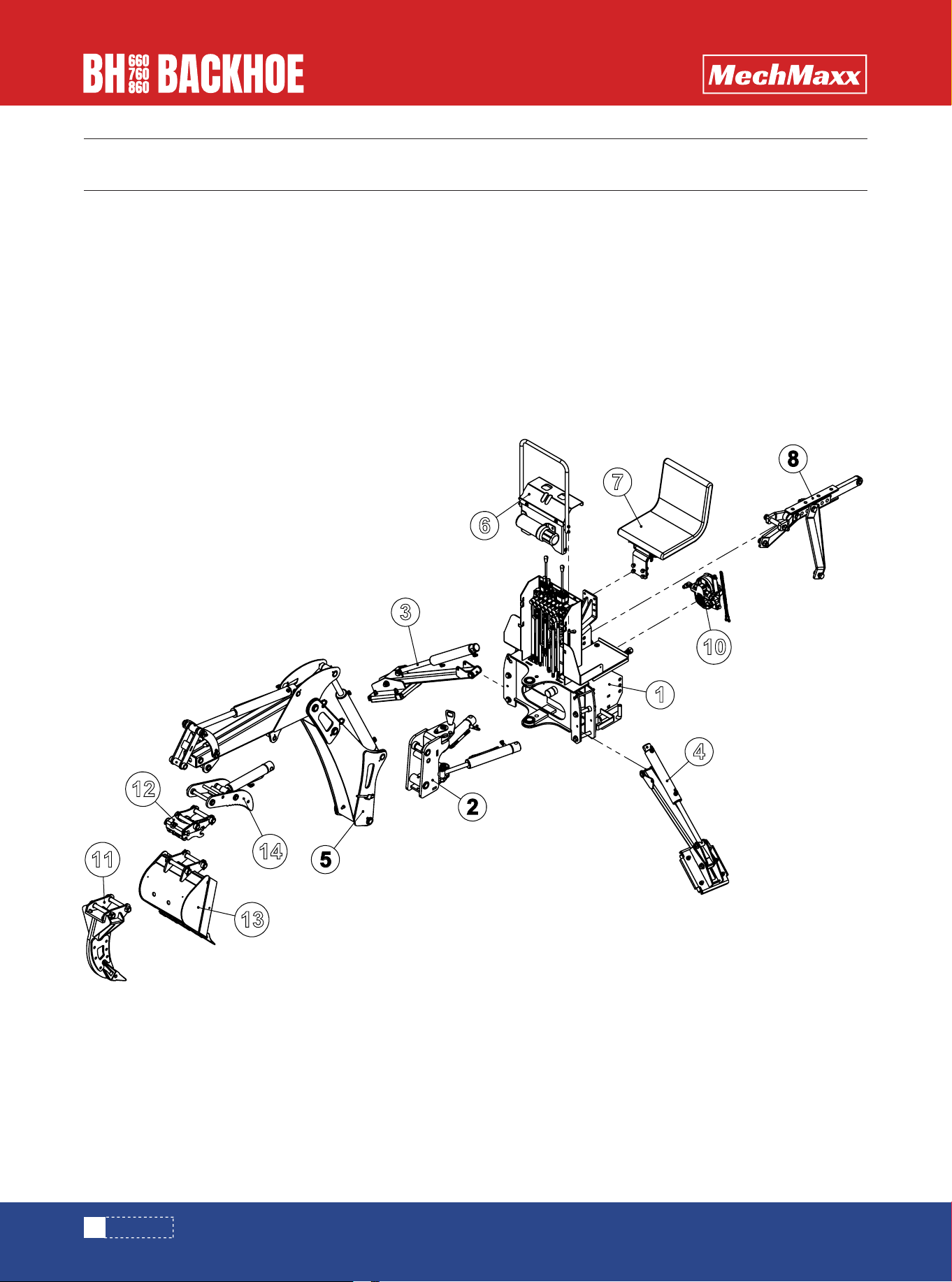
BASE ASSEMBLY

21
www.mechmaxx.com
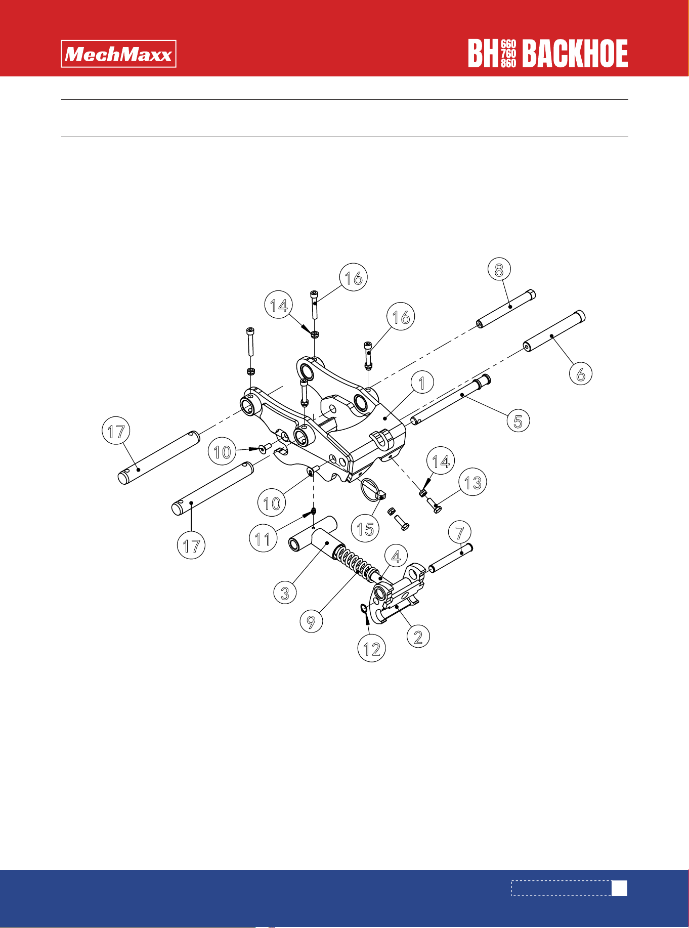
BASE ASSEMBLY
PARTS LIST (BASE ASSEMBLY)
,7(0 '(6&5,37,21 63(&,),&$7,21 47<
%DVHDVVHPEO\ZHOGLQJ %+2%
0XOWLSOH[YDOYHDVVHPEO\ %+2
3LSH3OXJ ĭ[0;
3LQ %+2
+H[DJRQ)LW6KDQN%ROWV *%B70î(3=Q
6SULQJZDVKHU *%B7î(3B=Q
+H[DJRQ7KLQ1XW *%B70(3B=Q
+H[DJRQ)LW6KDQN%ROWV *%B70î(3=Q
EXVKLQJ ĭ;ĭ;PP
6SULQJ&RWWHUV ĭî(3B=Q
3LQ %+2
3ODLQ:DVKHU *%B7î(3B=Q
6SULQJ&RWWHUV ĭî(3B=Q
/RZHUVXVSHQVLRQSLQVKDIWVSDFHU %+2

22
www.mechmaxx.com
PARTS DIAGRAM (MULTIPLEX VALVE ASSEMBLY)
MULTIPLEX VALVE ASSEMBLY

23
www.mechmaxx.com
MULTIPLEX VALVE ASSEMBLY
PARTS LIST (MULTIPLEX VALVE ASSEMBLY)
,7(0 '(6&5,37,21 63(&,),&$7,21
2LO,QOHW+RVH)RU+\GUDXOLF
'LUHFWLRQDO9DOYH
%+2
2LO5HWXUQ+RVH)RU+\GUDXOLF
'LUHFWLRQDO9DOYH
%+2
+\GUDXOLF+RVH6 %+2
+\GUDXOLF+RVH6 %+2&
+\GUDXOLF+RVH6 %+2
+\GUDXOLF+RVH6 %+2
+\GUDXOLF+RVH %+2
+\GUDXOLF+RVH %+2-;&
+\GUDXOLF+RVH %+2
+\GUDXOLF+RVH %+2-;
+\GUDXOLF+RVH %+2&
+\GUDXOLF+RVH %+2
+\GUDXOLF+RVH %+2
+\GUDXOLF+RVH %+2
+\GUDXOLF+RVH %+2
+\GUDXOLF+RVH %+2
3ODWH %+2
+\GUDXOLF+RVH %+2&
+\GUDXOLF+RVH %+2
+\GUDXOLF+RVH %+2
+\GUDXOLF+RVH %+2
+\GUDXOLF+RVH %+2
+\GUDXOLF+RVH %+2
+\GUDXOLF+RVH %+2
+\GUDXOLF+RVH %+2
+\GUDXOLF+RVH %+2&
+\GUDXOLF+RVH %+2
+\GUDXOLF+RVH %+2
47<
47<
47<

24
www.mechmaxx.com
MULTIPLEX VALVE ASSEMBLY
,7(0 '(6&5,37,21
63(&,),&$7,21
4
7<
4
7<
4
7<
+\GUDXOLF+RVH %+2
+\GUDXOLF+RVH %+2
+\GUDXOLF+RVH %+2
+\GUDXOLF+RVH %+2
+\GUDXOLF+RVH %+2
5LJLG7XEH %+2
5LJLG7XEH %+2
5LJLG7XEH %+2
5LJLG7XEH %+2
5LJLG7XEH %+2
5LJLG7XEH %+2
&RPELQDWLRQZDVKHU
VHOIFHQWHULQJ
%6⩙$îî⩙*⩙
&RPELQDWLRQZDVKHU
VHOIFHQWHULQJ
%6⩙$îî⩙
+H[DJRQ+HDG%ROWV *%B70î(3B=1
+H[DJRQ+HDG%ROWV *%B70î(3B=1
+H[DJRQ+HDG%ROWV *%B70î(3B=1
+H[DJRQ6RFNHW+HDG
&DS6FUHZV
*%B70î(3B=Q
+H[DJRQ6RFNHW%XWWRQ
+HDG6FUHZV
*%B70î(3B=Q
6SULQJZDVKHU *%B7î(3B=Q
3ODLQ:DVKHU *%B7(3B=Q
$GDSWHU/
81)⩙
+ROORZVFUHZV/
81)⩙
$GDSWHU/
81)⩙
+ROORZVFUHZV/
81)⩙
+\GUDXOLF'LUHFWLRQDO9DOYH 89755
+\GUDXOLF'LUHFWLRQDO9DOYH 906
+\GUDXOLF'LUHFWLRQDO9DOYH 907
25
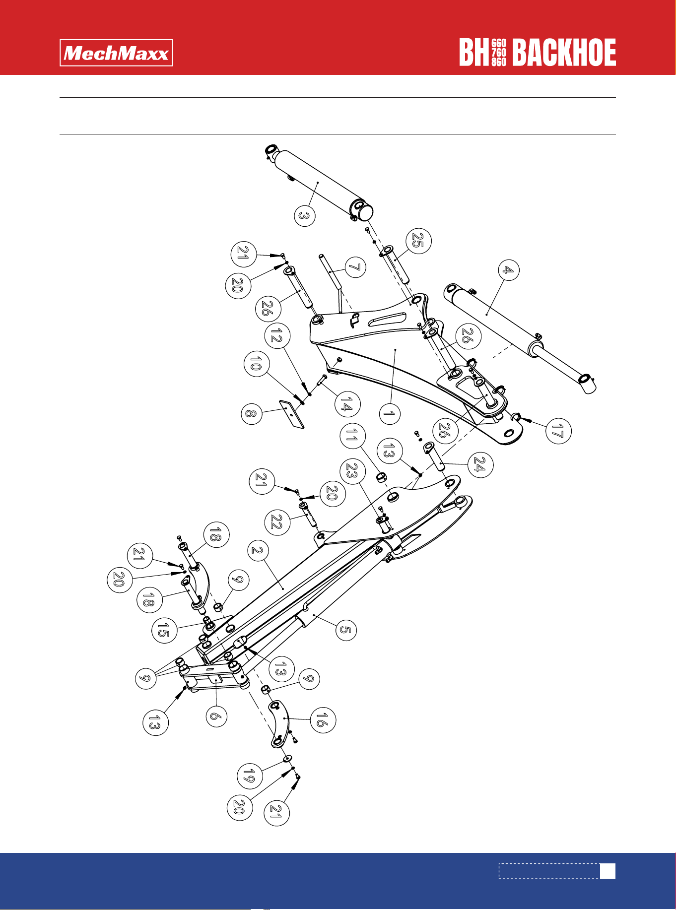
www.mechmaxx.com
STEERING ASSEMBLY
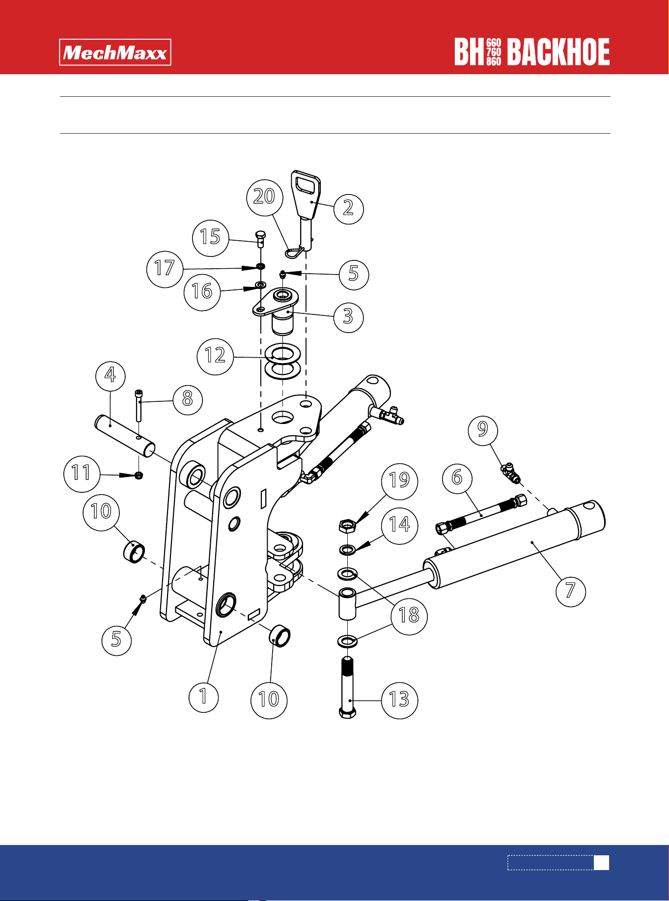
PARTS DIAGRAM (STEERING ASSEMBLY)
2
20
15
17
16
3
5
12
9
7
6
19
14
18
1310
1
5
10
11
8
4

26
www.mechmaxx.com
STEERING ASSEMBLY
PARTS LIST (STEERING ASSEMBLY)
,7(0 '(6&5,37,21 63(&,),&$7,21
4
7<
7KHURWDU\MRLQWVDUHZHOGLQJ %+2
3LQ %+2
6SLQGOH:LUH$VVHPEO\ %+2%
3LQ %+2
*UHDVHQLSSOH -%B70î
+\GUDXOLF+RVH %+2
+\GUDXOLFF\OLQGHU %+2
+H[DJRQVRFNHWKHDGFDSVFUHZV
7UDQVLWLRQMRLQWV
*%B70î(3 =Q
%XVKLQJ ĭ;ĭ;PP
3UHYDLOLQJWRUTXHW\SHKH[DJRQQXW *%B70(3B=Q
$GMXVWLQJ6KLP %+2
+H[DJRQ)LW6KDQN%ROWV *%B70î(3=Q
6SULQJZDVKHU *%B7î(3B=Q
+H[DJRQ+HDG%ROW)XOO7KUHDG *%B70î(3=Q
3ODLQ:DVKHU *%B7î(3B=Q
6SULQJZDVKHU *%B7î(3B=Q
3ODLQ:DVKHU *%B7î(3B=Q
+H[DJRQ7KLQ1XW *%B70(3B=Q
6SULQJ&RWWHUV ĭî(3B=Q
81)⩙
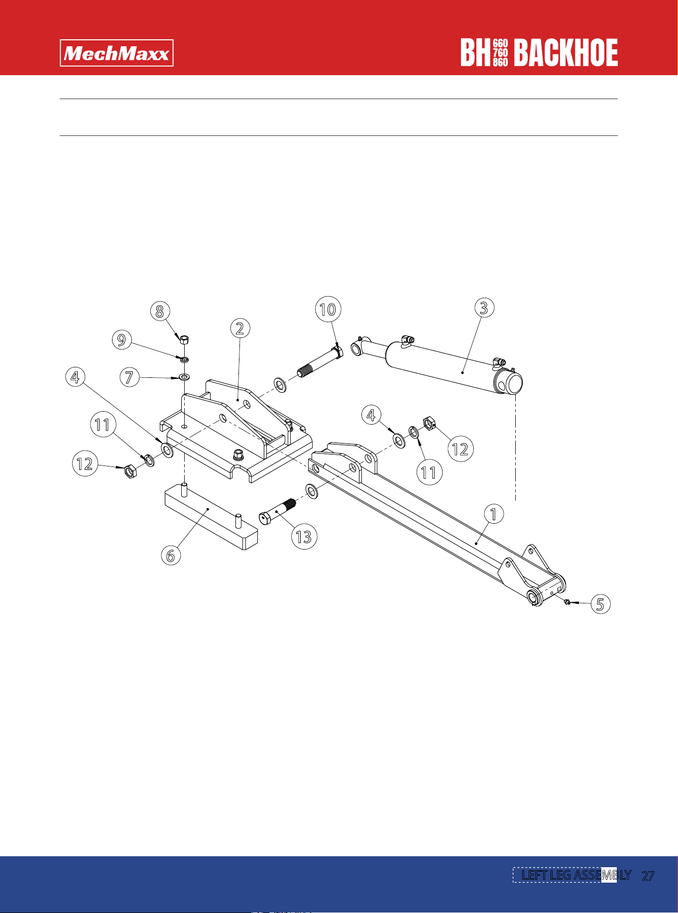
www.mechmaxx.com
L
EFT LEG ASSEMBLY
2
7
PARTS DIAGRAM (LEFT LEG ASSEMBLY)
11
8
10
2
4
3
1
5
12
9
13
11
7
6
12
4

LEFT LEG ASSEMBLY
28
www.mechmaxx.com
PARTS LIST (LEFT LEG ASSEMBLY)
ITEM DESCRIPTION SPECIFICATION QTY
1
2
3
4
5
6
7
8
9
10
11
12
13
Poles are welding
Bottom plate welding
Hydraulic cylinder
Grease nipple
Rubber sheet
Plain Washer
Hexagon Nuts
Spring washer
Hexagon Thin Nut
Hexagon Fit Shank Bolts
Spring washer
Plain Washer
Hexagon Fit Shank Bolts
BHO76-006
BHO76-007
BHO-133
JB_T7940.1-M8x1
BHO76-200
GB_T95-12×2.5-EP_Zn
GB_T41-M12-EP_Zn
GB_T93-12x3.1-EP_Zn
GB_T6172.1-M20-EP_Zn
GB_T93-20x5-EP_Zn
GB_T95-20x3-EP_Zn
GB_T27-M20x120-8.8-EP-Zn
GB_T27-M20x90-8.8-EP-Zn
1
1
1
1
2
4
4
4
2
2
1
4
1
29
www.mechmaxx.com
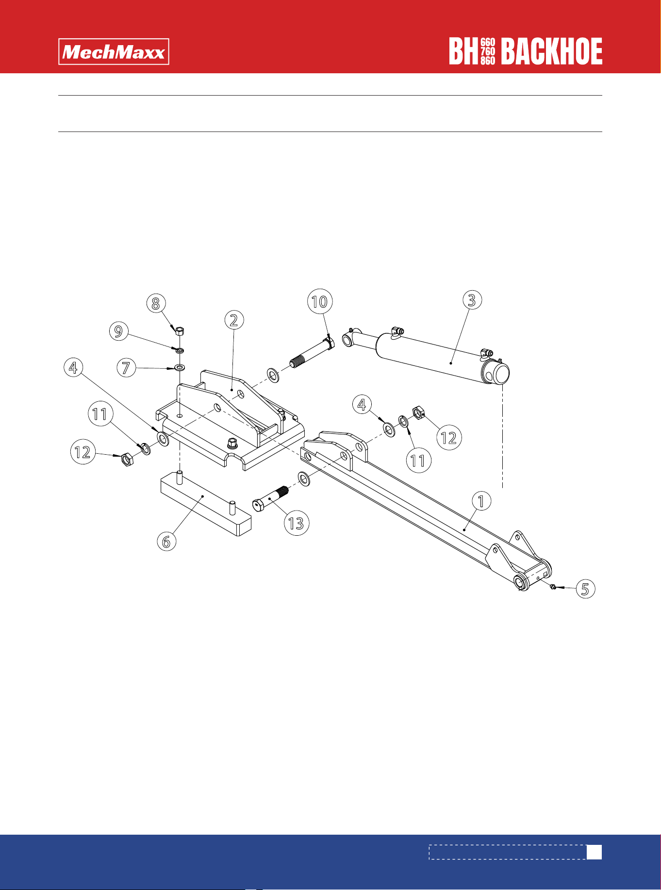
PARTS DIAGRAM (RIGHT LEG ASSEMBLY)
PARTS DIAGRAM (RIGHT LEG ASSEMBLY)
11
8
10
2
4
3
1
5
12
9
13
11
7
6
12
4

30
www.mechmaxx.com
RIGHT LEG ASSEMBLY
PARTS LIST (RIGHT LEG ASSEMBLY)
ITEM DESCRIPTION SPECIFICATION QTY
1
2
3
4
5
6
7
8
9
10
11
12
13
Poles are welding
Bottom plate welding
Hydraulic cylinder
Grease nipple
Rubber sheet
Plain Washer
Hexagon Nuts
Spring washer
Hexagon Thin Nut
Hexagon Fit Shank Bolts
Spring washer
Plain Washer
Hexagon Fit Shank Bolts
BHO76-006
BHO76-007
BHO-133
JB_T7940.1-M8x1
BHO76-200
GB_T95-12×2.5-EP_Zn
GB_T41-M12-EP_Zn
GB_T93-12x3.1-EP_Zn
GB_T6172.1-M20-EP_Zn
GB_T93-20x5-EP_Zn
GB_T95-20x3-EP_Zn
GB_T27-M20x120-8.8-EP-Zn
GB_T27-M20x90-8.8-EP-Zn
1
1
1
1
2
4
4
4
2
1
2
4
1
31
www.mechmaxx.com
MOVING ARM ASSEMBLY
PARTS DIAGRAM (MOVING ARM ASSEMBLY)

32
www.mechmaxx.com
MOVING ARM ASSEMBLY
PARTS LIST (MOVING ARM ASSEMBLY)
,7(0 '(6&5,37,21 63(&,),&$7,21
47<
47<
47<
/DUJHPRYDEOHDUPZHOGLQJ %+2%
/DUJHPRYDEOHDUPZHOGLQJ %+2%
/DUJHPRYDEOHDUPZHOGLQJ %+2%
6PDOOPRYLQJDUPZHOGLQJ %+2%
6PDOOPRYLQJDUPZHOGLQJ %+2%
6PDOOPRYLQJDUPZHOGLQJ %+2%
0RYLQJDUPDVVHPEO\ %+2
0RYLQJDUPDVVHPEO\ %+2
0RYLQJDUPDVVHPEO\ %+2
+\GUDXOLFF\OLQGHU %+2
+\GUDXOLFF\OLQGHU %+2
+\GUDXOLFF\OLQGHU %+2
+\GUDXOLFF\OLQGHU %+2
+\GUDXOLFF\OLQGHU %+2
+\GUDXOLFF\OLQGHU %+2
&RQQHFWLQJURGEDVHEUDFNHW
ZHOGLQJ
%+2
3LQZHOGLQJ %+2%
3ODWH %+2
%XVKLQJ ĭ;ĭ;PP
3ODLQ:DVKHU *%B7î(3B=Q
%XVKLQJ ĭ;ĭ;PP
6SULQJZDVKHU *%B7î(3B=Q
*UHDVHQLSSOH -%B70î
+H[DJRQ+HDG%ROW)XOO7KUHDG *%B70î(3=Q
%XVKLQJ ĭ;ĭ;PP
&RQQHFWLQJURGZHOGLQJ %+2%
+RVH&ODPSV -%B7ĭaĭ
3LQ %+2
3ODWH %+2
6SULQJZDVKHU *%B7î(3B=Q
+H[DJRQ+HDG%ROW)XOO7KUHDG *%B70î(3=Q
3LQ %+2
3LQ %+2
3LQ %+2
3LQ %+2
3LQ %+2
33
www.mechmaxx.com
CONSOLE ASSEMBLY
PARTS DIAGRAM (CONSOLE ASSEMBLY)

34
www.mechmaxx.com
CONSOLE ASSEMBLY
PARTS LIST (CONSOLE ASSEMBLY)
,7(0 '(6&5,37,21 63(&,),&$7,21 47<
)URQWFRYHUSODWHRIFRQWUROFDELQHW %+2
3ODWH %+2
3ROHV %+2
3ODLQ:DVKHUV/DUJH6HULHV *%B7(3B=Q
6SULQJZDVKHU *%B7î(3B=Q
+H[DJRQ6RFNHW%XWWRQ+HDG6FUHZV *%B70î(3B=Q
3ODLQ:DVKHU *%B7(3B=Q
+H[DJRQ+HDG%ROW)XOO7KUHDG *%B70î(3=Q
0DQXDOFDQLVWHU 70
+H[DJRQ6RFNHW&RXQWHUVXQN+HDG *%B70î(3B=Q
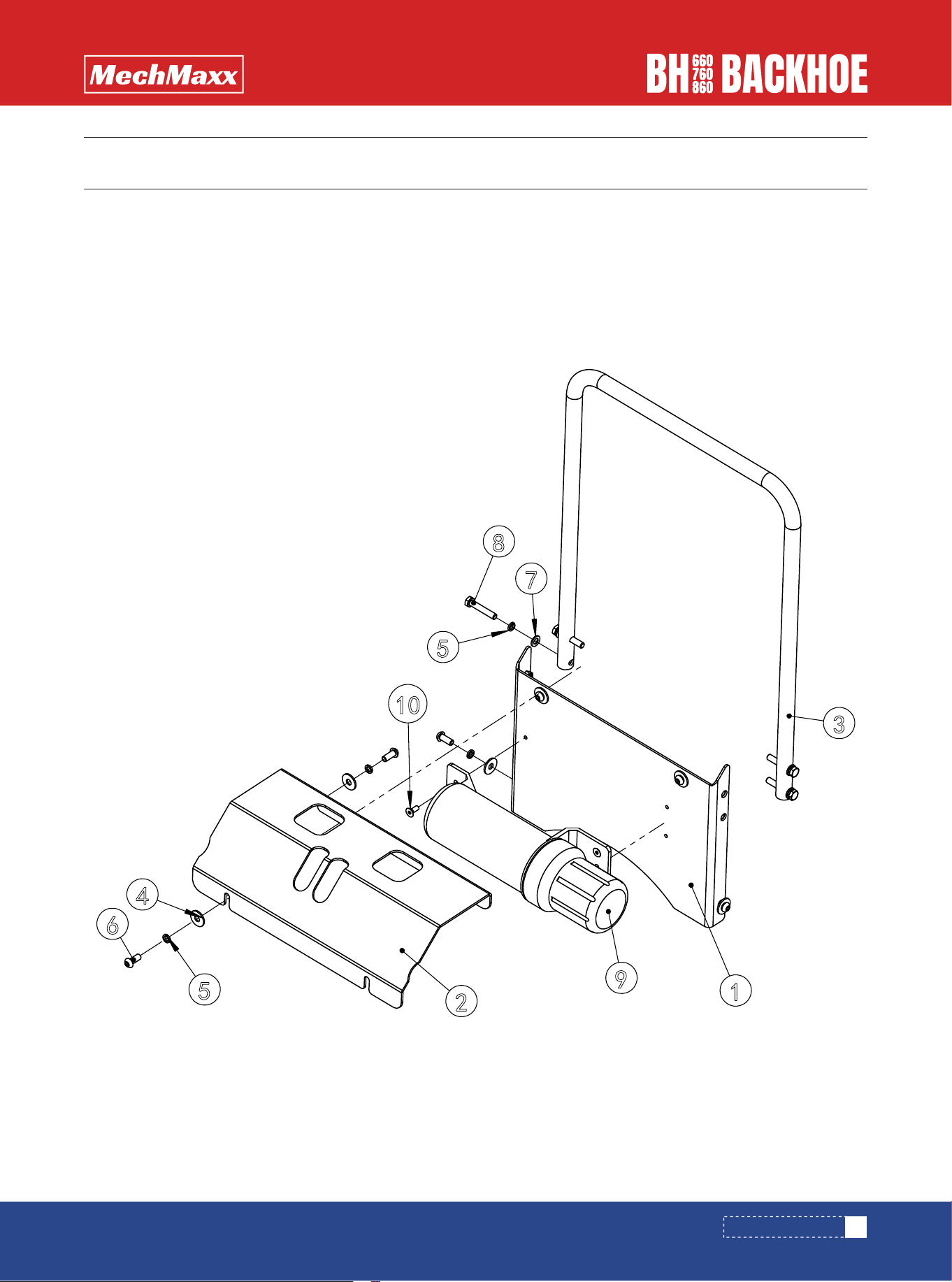
PARTS DIAGRAM (SEAT ASSEMBLY)
35
www.mechmaxx.com
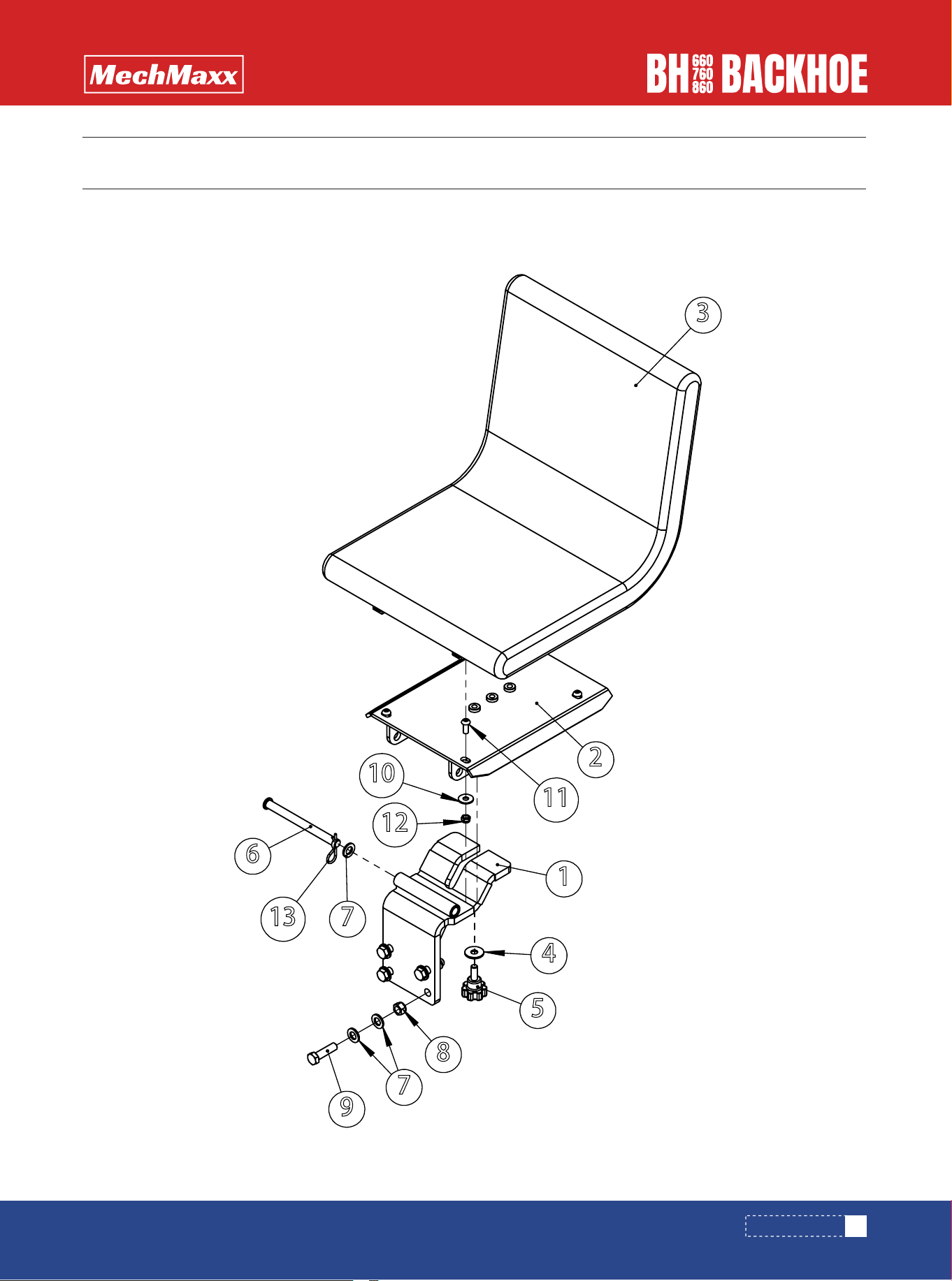
SEAT ASSEMBLY
3
2
11
10
12
1
4
5
8
7
9
713
6

36
www.mechmaxx.com
SEAT ASSEMBLY
PARTS LIST (SEAT ASSEMBLY)
,7(0 '(6&5,37,21 63(&,),&$7,21 47<
%DVHVXSSRUWSODWHZHOGLQJ %+2
%RWWRPSODWHZHOGLQJ %+2
&KDLU ;5
3ODLQ:DVKHUV/DUJH6HULHV *%B7(3B=Q
5XEEHUUHG 0î
3LQ %+2
3ODLQ:DVKHU *%B7î(3B=Q
3UHYDLOLQJWRUTXHW\SHKH[DJRQQXW *%B70(3B=Q
+H[DJRQ+HDG%ROW)XOO7KUHDG *%B70î(3=Q
3ODLQ:DVKHUV/DUJH6HULHV *%B7(3B=Q
+H[DJRQ6RFNHW%XWWRQ+HDG6FUHZV *%B70î(3B=Q
3UHYDLOLQJWRUTXHW\SHKH[DJRQQXW *%B70(3B=Q
6SULQJ&RWWHUV ĭî(3B=Q
PARTS DIAGRAM (BASE CONNECTING ROD ASSEMBLY)
37
www.mechmaxx.com
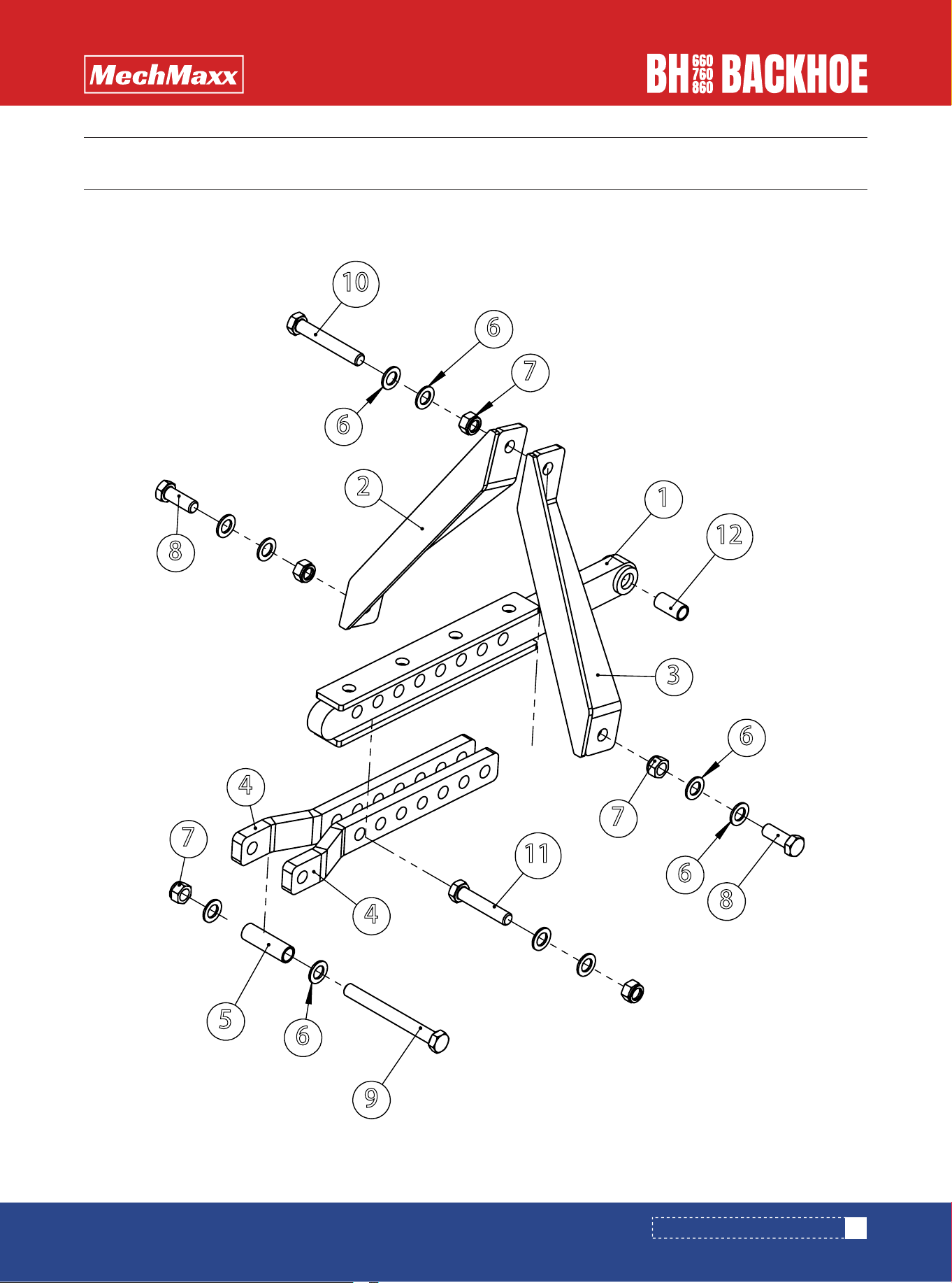
BASE CONNECTING ROD ASSEMBLY
10
6
6
7
2
3
12
1
8
6
6
7
9
5
6
7
11
8
4
4

38
www.mechmaxx.com
BASE CONNECTING ROD ASSEMBLY
PARTS LIST (BASE CONNECTING ROD ASSEMBLY)
,7(0 '(6&5,37,21 63(&,),&$7,21 47<
3XOO5RGDVVHPEO\ %+2
%DVHFRQQHFWLQJURGZHOGLQJ %+2
%DVHFRQQHFWLQJURGZHOGLQJ %+2
3ROHV %+2
7XEH %+2
3ODLQ:DVKHU *%B7î(3B=Q
3UHYDLOLQJWRUTXHW\SHKH[DJRQQXW *%B70(3B=Q
+H[DJRQ+HDG%ROW)XOO7KUHDG *%B70î(3=Q
+H[DJRQ+HDG%ROWV *%B70î(3B=1
+H[DJRQ+HDG%ROWV *%B70î(3B=1
+H[DJRQ+HDG%ROWV *%B70î(3B=1
VXVSHQVLRQSLQVKDIWVSDFHU %+2

PARTS DIAGRAM (THE FUEL TANK ASSEMBLY)
39
www.mechmaxx.com
THE FUEL TANK ASSEMBLY

40
www.mechmaxx.com
THE FUEL TANK ASSEMBLY
ITEM DESCRIPTION SPECIFICATION QTY
1
2
3
4
5
6
7
8
9
10
11
12
13
14
15
16
17
18
19
The fuel tank welding
Breather filter
Hydraulic Hose
Breather filter
Breather filter
BREATHER FILTER SERIES
Content gauge
Transition joints
Outer hexagonal plug
Combined sealing gaskets
Combined sealing gaskets
O-ring
Plain Washers - Large Series
Spring washer
Hex socket flat round head screw
Plain Washer
Spring washer
Hexagon Head Bolt - Full Thread
Hexagon socket head cap screws
BHO76-019
BHO76-020
BHO-138
RFA-25-10L
WU-25X100-J
AF22
YWZ-80T
M22×1.5ED/UNF3/4-16
JB_ZQ4770-M16x1.5
BS/ A16.4x22x25- M16
BS/ A22.5x30x2.5-M22
NBRΦ60x3.5
GB_T96.2-10-EP_Zn
GB_T93-10x2.6-EP_Zn
GB_T70.2-M10x30-N
GB_T95-8-EP_Zn
GB_T93-8x2.1-EP_Zn
GB_T5783-M8x16-8.8-EP-Zn
GB_T70.1-M8x20-8.8-EP_Zn
1
1
1
1
1
1
1
1
1
1
1
1
4
4
4
6
10
6
4
PARTS LIST (THE FUEL TANK ASSEMBLY)
41
www.mechmaxx.com
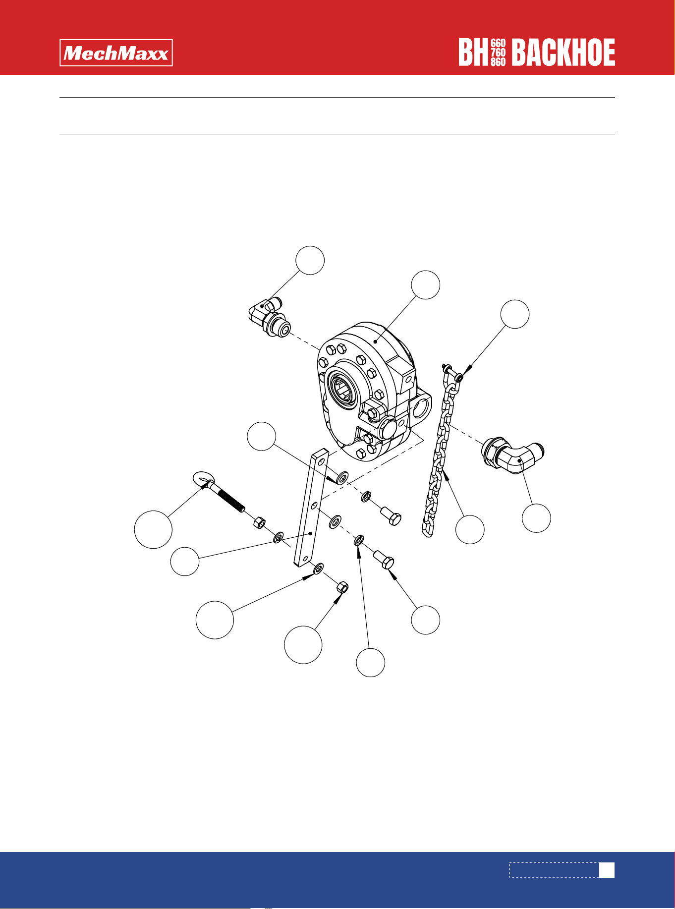
PTO PUMP ASSEMBLY
PARTS DIAGRAM (PTO PUMP ASSEMBLY)

42
www.mechmaxx.com
PTO PUMP ASSEMBLY
PARTS LIST (PTO PUMP ASSEMBLY)
+\GUDXOLFSXPS &%3/-+
+\GUDXOLFSXPS &%3/-+
7UDQVLWLRQMRLQWV 81)81)
7UDQVLWLRQMRLQWV 81)81)
3ODWH %+2
'ULQJ -%BPP
*DOYDQL]HGFKDLQ îî
3ODLQ:DVKHU *%B7[(3B=Q
6SULQJZDVKHU *%B7[(3B=Q
+H[DJRQ+HDG%ROW)XOO7KUHDG *%B70[(3=Q
%ROW *%B70[ĭ(3=Q
3ODLQ:DVKHU *%B7[(3B=Q
+H[DJRQ1XW *%B70(3B=Q
,7(0 '(6&5,37,21 63(&,),&$7,21
47<
43
www.mechmaxx.com
QUICK CHANGE SYSTEM
PARTS DIAGRAM (QUICK CHANGE SYSTEM)

44
www.mechmaxx.com
QUICK CHANGE SYSTEM
PARTS LIST (QUICK CHANGE SYSTEM)
,7(0 '(6&5,37,21 63(&,),&$7,21 47<
%+2
45%UDFNHW:HOGPHQW
%+2
/DWFK+RRN:HOGPHQW
%+2
/DWFK5RG:HOGPHQW
%+2
)URQW5RG:HOGPHQW
%+2
3LQ
%+2
3LQ
%+2
3LQ
%+2
3LQ
ĭîĭ
6SULQJ
*%B70î(3B=Q
+H[DJRQ6RFNHW&RXQWHUVXQN+HDG6FUHZ
-%B70î
*UHDVHQLSSOH
*%B7$
&LUFOLSIRUVKDIWW\SH
*%B70î(3=Q
+H[DJRQ+HDG%ROW)XOO7KUHDG
*%B70(3B=Q
3UHYDLOLQJWRUTXHW\SHKH[DJRQQXW
',1;(3=Q
6DIHW\SLQ
*%B70î(3B=Q
+H[DJRQVRFNHWKHDGFDSVFUHZV
%+2
3LQ
45
www.mechmaxx.com
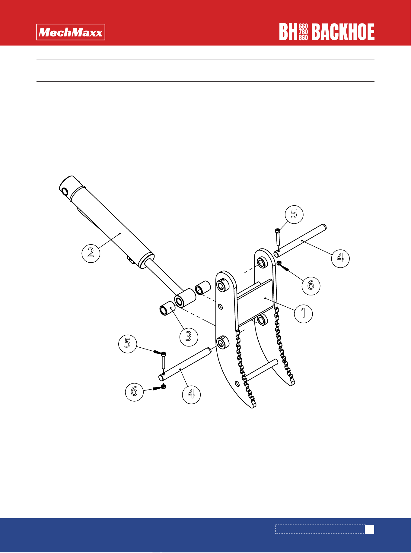
HYDRAULIC LOG GRAB COMPONENTS
PARTS DIAGRAM (HYDRAULIC LOG GRAB COMPONENTS)
1
5
6
4
2
4
6
5
3

46
www.mechmaxx.com
HYDRAULIC LOG GRAB COMPONENTS
PARTS LIST (HYDRAULIC LOG GRAB COMPONENTS)
,7(0 '(6&5,37,21 63(&,),&$7,21 47<
+ROGIRUN:HOGPHQW %+2
+\GUDXOLFF\OLQGHU %+2
7XEH %+2
3LQ %+2
+H[DJRQVRFNHWKHDGFDSVFUHZV *%B70î(3B=Q
3UHYDLOLQJWRUTXHW\SHKH[DJRQQXW *%B70(3B=Q
www.mechmaxx.com
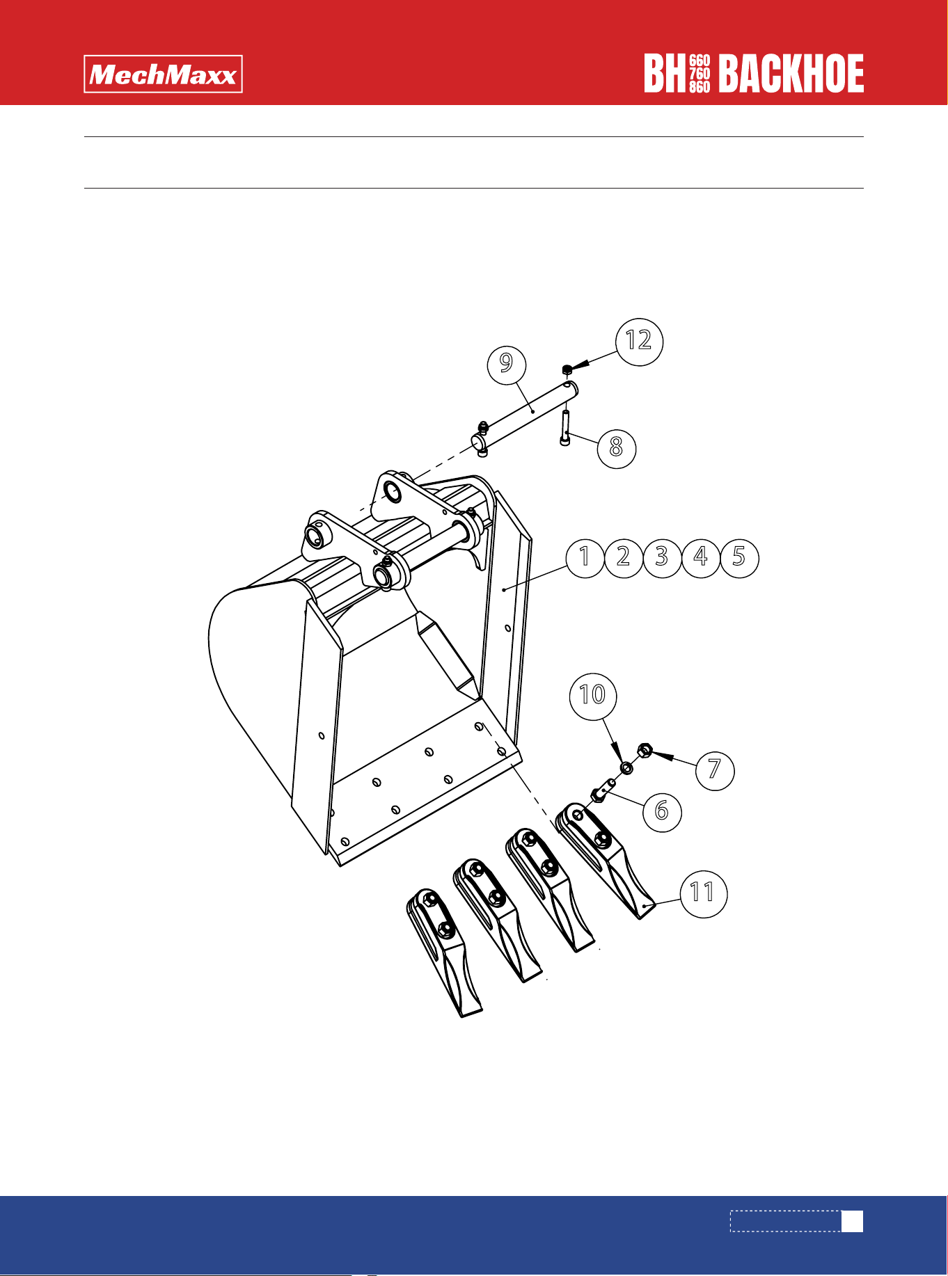
BUCKET ASSEMBLY
47
PARTS DIAGRAM (BUCKET ASSEMBLY)
8
12
7
10
6
11
1 2 3 4 5
9

www.mechmaxx.com
48
BUCKET ASSEMBLY
PARTS LIST (BUCKET ASSEMBLY)
%XFNHWZHOGLQJSDUWV %+2
%XFNHWZHOGLQJSDUWV %+2
%XFNHWZHOGLQJSDUWV %+2
%XFNHWZHOGLQJSDUWV %+2
%XFNHWZHOGLQJSDUWV %+2
+H[DJRQ+HDG%ROW)XOO7KUHDG *%B70îî(3B=1
+H[DJRQ1XW *%B70î(3B=Q
+H[DJRQVRFNHWKHDGFDSVFUHZV *%B70î(3B=Q
3LQ %+2
6SULQJZDVKHU *%B7î(3B=Q
6FUDSHU.QLIH %+2
3UHYDLOLQJWRUTXHW\SHKH[DJRQQXW*%B70(3B=Q
'(6&5,37,21,7(0
47<
63(&,),&$7,21