Loading ...
Loading ...
Loading ...
SERVICE
81
MAINTENANCE INSTRUCTIONS
2.
Place rod wiper
(3G)
in outer gland groove.
Slide gland assembly
(8)
onto rod. Place wear
ring
(3B)
in wide groove of piston. Place O
-
ring
(3C) and piston seal (3D) in narrow piston
groove.
3.
Lightly coat rod threads with hydrauvc oil and
slide O
-
ring (3A) over threads and into groove.
Install piston
(7)
onto rod
(4)
with wear ring on
side away from gland. Install locknut
(6)
and
torque
to
175
ft
-
lbs.
4.
Compress wear ring and piston seal and
carefully insert piston and rod assembly into
barrel. Use care to prevent damage while
installing.
5.
Install collar
(2)
onto barrel
(9)
and tighten.
Tighten set screw.
/
Lock Wire or Threaded
Plug
Style
Cylinder (Figure
30)
Note: Cylinders used in the same application are
provided
from.two suppliers. One uses
a
lock wire
and one uses
a
threaded plug for
a
locking device.
Lock wire cylinders
can
be identified by
the
“L”
stamped on butt end of cylinder.
All
threaded plug cylinders have
an
“E”
stamped
on
butt end of cylinder.
Be sure to make the proper manufacturer
identification before ordering repair parts.
Lock Wire Removal (Cylinder
stamped
“L”)
Insert
a
screwdriier into slot in barrel. Pry up on
end of lock wire
and
turn gland until lock wire feeds
out through slot.
Threaded
Plug
Removal
-
(Cylinder
stamped
“E”)
Unscrew threaded plug using
a
spanner wrench,
or
carefully use punch and hammer to remove.
DISASSEMBLY
1.
Remove piston and rod assembly from barrel.
2.
Clamp
cross
pin end of rod assembly in vise
with protective jaws. Remove locknut from rod.
3.
Remove and discard all seals, wear rings and
O
-
rings.
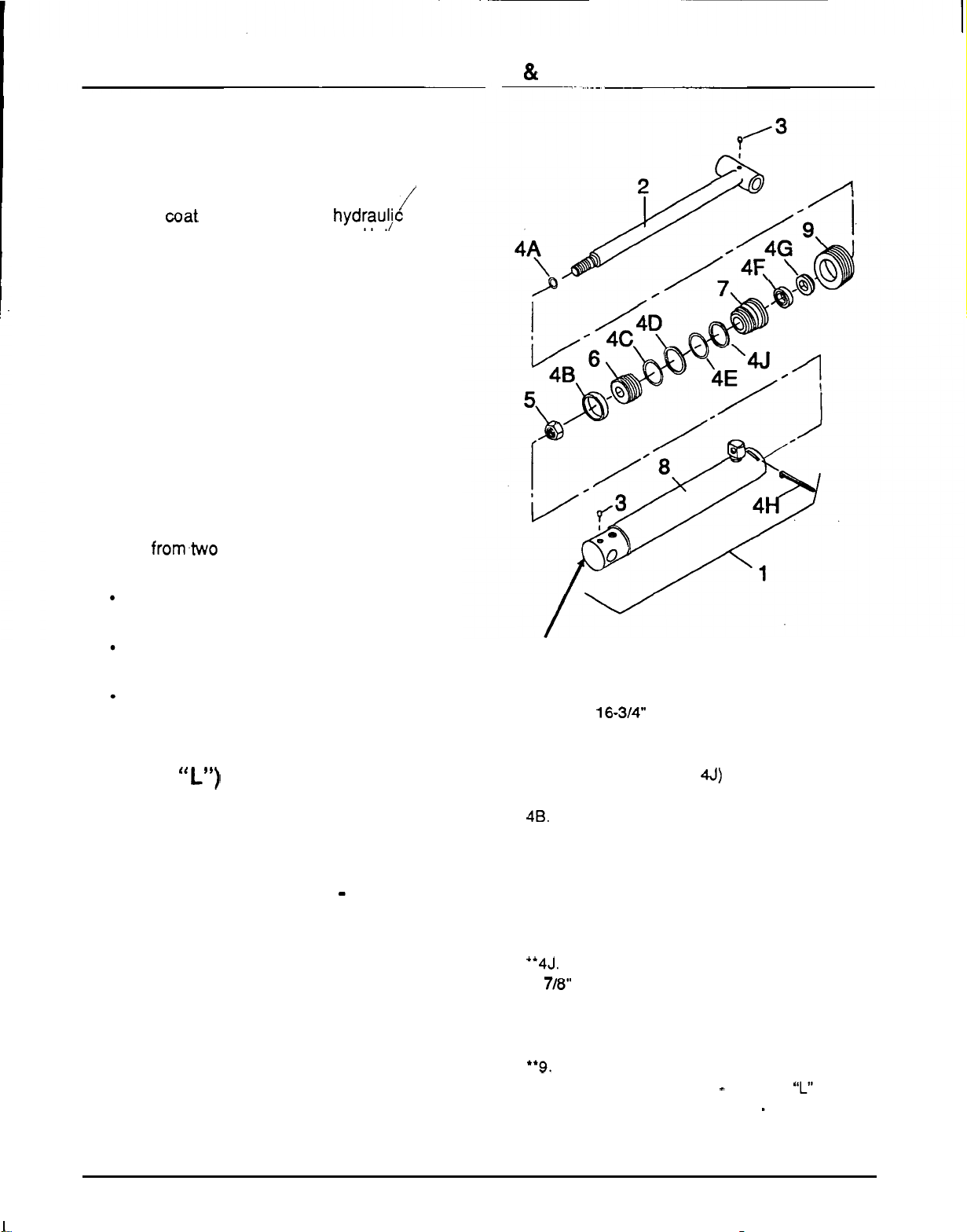
IDENTIFICATION
STAMP
1.
2
-
1/2
x
16-3”’
Hydraulic cylinder
2.
Rod
assembly
3.
1/4
-
28
Grease fitting
4.
Seal
kit
(contains
4A
-
4J)
4A.
Rod
static seal
48. Wear strip
4C.
0
-
Ring
4D.
Piston seal
4E. Gland static seal
4F.
Rod seal
4G. Rod wiper
‘4H. Lock
wire
“4J. Back
-
up washer
5.
7/8“
Self
-
lock hex nut
6.
Piston
7.
Gland
8.
Barrel assembly
**9.
Threaded retainer
‘Used on lock wire cylinder
-
stamped
“L”
**Used on threaded plug cylinder
-
stamped
“E”
Figure
30.
Hydraulic Cylinder
(Lock
Wire
or
Threaded
Plug
Style)
40
Loading ...
Loading ...
Loading ...