Loading ...
Loading ...
Loading ...
SDS5000X Series Digital Oscilloscope User Manual
53 / 2 3 6 W W W. S I G L E N T. C O M
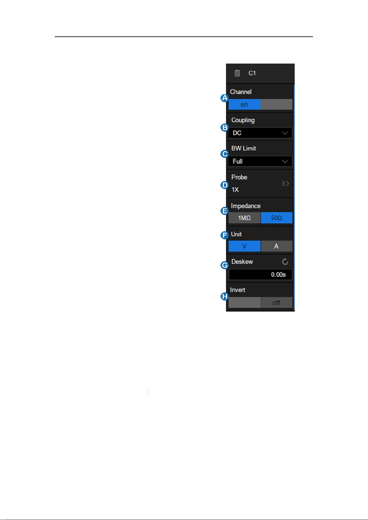
A. Turn channel on/off
B. Coupling (DC, AC or GND)
C. Bandwidth limit (Full, 200 MHz or 20
MHz)
D. Probe attenuation (1X, 10X, 100X or
custom)
E. Impedance
F. Units for the channel
G. Deskew
H. Enable/disable invert
Coupling
DC: All of the input signal frequency components are passed to the display.
AC: The signal is capacitively coupled. DC signal components are rejected.
See the datasheet for details of the cut-off frequency. AC coupling is
suitable for observing AC signals with DC offset, such as power ripple.
GND: The channel is grounded by an internal switch. GND coupling is used
to observe the zero offset error of the analog channels, or determine the
source of noise in the waveform (from signal or from oscilloscope itself)
Loading ...
Loading ...
Loading ...