Loading ...
Loading ...
Loading ...
STEP I 0
nnstalling the Anti-Tip Device
WARNING:
o Range must be secured with an approved Anti-
Tip device,
° Unless properly inst_led, the range could be
tipped by you or a child standing, sitting or
leaning on an open door.
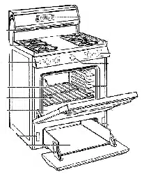
• After installing the Anti-Tip device, verify that it
is properly installed and engaged by removing the
storage drawer and inspecting the rear leveling
leg, Make sure it fits securely into the slot.
• This range has been designed to meet all
recognized industry tip standards for all normal
conditions_
• The installation of the Anti-Tip device must meet
all local codes for securing the appliance.
• The use of this device does not preclude tipping
of the range when not properly installed,
• If the Anti-Tip device supplied with the range
does not fit this application, use the universal
Anti+Tip device WB02X7909.
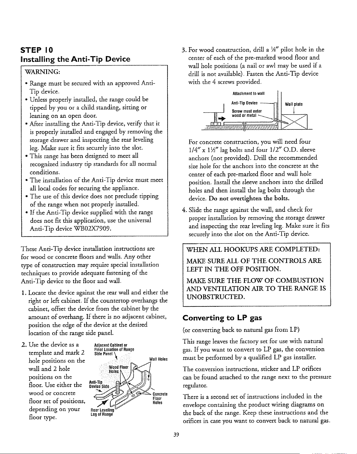
3. For wood construction, drill a 1A" pilot hole in the
center of each of the pre-marked wood floor and
wall hole positions (a nail or awl may be used if a
drill is not available), Fasten the Anti-Tip device
with the 4 screws provided°
Anti+TipDevice Wall piate
l
woodor metal
For concrete construction, you will need four
I/4" x 1½" lag bolts and fdur 1/2" O.D, sleeve
anchors (not provided). Drill the recommended
size hole for the anchors into the concrete at the
center of each pre-marked floor and wall hole
position+ Install the sleeve anchors into the drilled
holes and then install the lag bolts through the
device. Do not overtighten the bolts.
4. Slide the range against the wall, and check for
proper installation by removing the storage drawer
and inspecting the rear leveling leg° Make sure it fits
securely into the slot on the Anti-Tip device.
These Anti-Tip device installation instructions are
for wood or concrete floors and walls. Any other
type of construction may require special installation
techniques to provide adequate fastening of the
Anti-Tip device to the floor and wall,
1, Locate the device against the rear wall and either the
right or left cabinet, If the countertop overhangs the
cabinet, offset the device from the cabinet by the
amount of overhang, If there is no adjacent cabinet,
position the edge of the device at the desired
location of the range side panel.
2. Use the device as a
template and mark 2
hole positions on the
wall and 2 hole
positions on the
floor. Use either the
wood or concrete
floor set of positions,
depending on your
floor type.
AdjacentCabtnelor
Hn_l Locatioflaf Range
Sld°P°,,eI' ;
Holes_.
ix
Aoti-Tlp :_L-+
DeviceSide ...4+t>"
LegofRange
WallHo_es
ele
Holes
WHEN ALL HOOKUPS ARE COMPLETED:
MAKE SURE ALL OF THE CONTROLS ARE
LEFT IN THE OFF POSITION,
MAKE SURE THE FLOW OF COMBUSTION
AND VENTILATION AIR TO THE RANGE IS
UNOBSTRUCTED,
Converting to LP gas
(or converting back to natural gas from LP)
This range leaves the factory set for use with natural
gas. If you want m convert to LP gas, the conversion
must be performed by a qualified LP gas installer.
The conversion instructions, sticker and LP orifices
can be found attached to the range next to the pressure
regulator+
There is a second set of instructions included in the
envelope containing the product wiring diagrams on
the back of the range° Keep these instructions and the
orifices in case you want to convert back to natural gas,
39
Loading ...
Loading ...
Loading ...