Loading ...
Loading ...
Loading ...
installation Instructions (cont oood
1. Install a manual gas line shut-offvalve in the gas
line in an easily accessed location outside of the
range. Make sure everyone operating the range
knows where and how to shut off the gas supply to
the range_
2. Install male 1/2" flare iinion adapter to the 1/2"
NPT internal thread elbow at inlet of' pressure
regulator. On models equipped with standard twin
burners, install the male pipe thread end of the 1/2"
flare union adapter to the 1/2" NPT internal thread
at inlet of pressure regulator. Use a back-up wrench
on the regulator fitting to avoid damage.
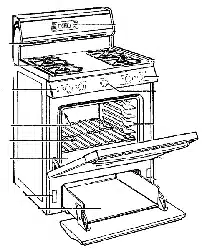
When installing the range from the front, remove
the 90 ° elbow for easier installation.
3. Install male 1/2" or 3/4" flare union adapter to the
NPT internal thread of the manual shut-off valve,
taking care to back up the shut-offvalve to keep it
f:om turning.
4. Connect flexible metal appliance connector to the
adapter on the range. Position range to permit
connection at the shut-offvalve.
5. When all connections have been made, mal:e sure
all range controls are in the OFF position and turn
on the main gas supply valve. Use a liquid leak
detector at all joints and connections to check for
leaks in the system.
CAUTION: DO NOT USE A FLAME TO
CHECK FOR GAS LEAKS.
When using test pressures greater than 1/2 psig to
pressure test the gas supply system of the residence,
disconnect the range and individual shut-offvalve
from the gas supply piping. When using test pressures
of 1/2 psig or less to test the gas supply system, simply
isolate the range from the gas supply system by closing
the individual shut-offvalve.
STEP 3
Electrical Connections
(on some models)
Hectrical Requirements
120-volt, 60 Hertz, properly grounded branch circuit
protected by a IS-amp or 20_amp circuit breaker or
time delay fuse.
Extension Cord Cautions
Because of potential safety hazards associated with
certain conditions, we strongly recommend against the
use of an extension cord. However, if you still elect to
use an extension cord, it is absolutely necessary that it
be a UL-listed, 3-wire grounding-type appliance
extension cord and that the current carrying rating of
the cord in amperes be equivalent to, or greater than,
the branch circuit rating.
GroundingwlMPORTANT (Hease read carefully)
FOR PERSONAL, SAFETY, THIS APPLIANCE
MUST BE PROPERLY GROUNDED.
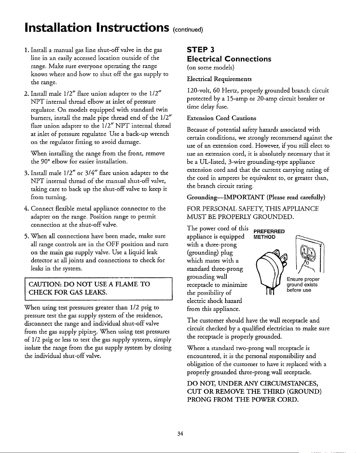
The power cord of this
appliance is equipped
with a three-prong
(grounding) plug
which mates with a
standard three-prong
grounding wall
receptacle to minimize
the possibility of
electric shock hazard
from this appliance.
PREFERRED
METHOD
The customer should have the wall receptacle and
circuit checked by a qualified electrician to make sure
the receptacle is properly grounded_
Where a standard two-prong wall receptacle is
encountered, it is the personal responsibility and
obligation of the customer to have it replaced with a
properly grounded three-prong wall Ieceptacle.
DO NOT, UNDER ANY CIRCUMSTANCES,
CUT OR REMOVE THE THIRD (GROUND)
PRONG FROM THE POWER CORD.
34
Loading ...
Loading ...
Loading ...