Loading ...
Loading ...
Loading ...
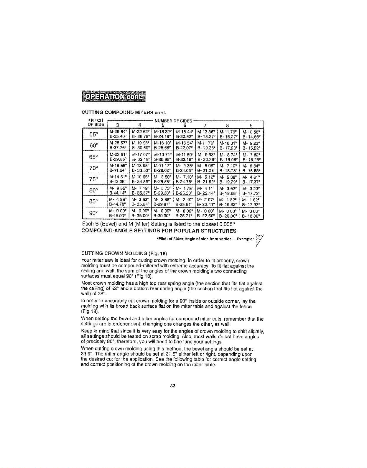
CUTTING COMPOUND MITERS canto
*PITCH NUMBER OFSIDES
OF StDE 3 4 5 6
M-29 84° M-22 62_ M-t8 32° M-1544 _
550 8_35.40= B- 28.78° B-24.t8 _' B_20.82_
M-26.57° M-1996 _ M-1610 n M-1354 °
600 B-37.76_' B- 30.60 _ B-25.65° B-22.07_
i M-22 9! _' M-1707 ° M-137t _' M-11 50_
650 B-39.85° B- 32.!9 ° 8-26.95° B-23.16 °
M-18 88° M-!3 95_' M-1t 17_ M-935 °
70e B-41.64° B- 33,53 ° B-28.02° R-24.06_
M-_4 5t = MqO 65° M- 850 '_ M- 7,10"
75 ° B.43,08_ B-34.59 ° B,28.88° B-24_78_
80 ° Me 985°i M° 7t9 _' M- 573 ° M- 478 '_
B.,|4.14.° B-35.37 ° B-29.50° B-25.30°
85 ° M- 498 _' M- 362 ° M- 288 ° M- 240 °
B-44.78'_ B- 35.84° B-29.87_' B-25.61°
_0o M* 0 00_ M- 000 ° M- 0,00_' M- 0,00_'
8-45.00 _ B- 36.00_ B-30.00° B-25.71°
7 8 9
M-t336 ° M-1t.79 ° M.1056 _
B-!8.27 '_ B_16.27o B_14,68°
...... , !
M-1170 ° M-1031 ° M- 923 _
a-19.3st, B-)7.,23°I B-15.52°
M-993° 1M. 874o 1 M-782 °
B-20.29 r' ! B-18.05 _ B-16.26 _
M-8o_; _-7io; M-e34_
B-21.08 _ B- 1&75 ° B- 16.88°
M- 612 = M- 538 ° M- 481 =
B- 21.69 _ B- 19.29" :B-17.37_
M- 4!1 '_ M- 362 ° M- 323 _
B-22.14 ° B-19.68 ° 8-17.72 °
M- 207 ° M- t82 ° M- 162 °
B-22,4t _' B-19.92 _' B-17.93 °
M- 000 ° M- 000 ° M- 000 °
B-22.50 ° B-20.00 '= B- 18.00_'
Each B (Bevel) and M (Miter) Setting is listed to the closest 0 005 o
COMPOUND-ANGLE SETTINGS FOR POPULAR STRUCTURES
*Pitch_f Side=Angleof sidefrom vertl_;a! Example;"i;_1_
CUTTING CROWN MOLDING (Fig. 18)
Your miter saw is ideal for cutting crown motding In order to fit properly, crown
mo_ding must be compound-mitered with extreme accuracy To fit Itat against lhe
ceiling and wall, the sum of the angles of the crown motdlng's two connecting
surfaces must equal g0° (Fig 18).
Most crown molding has a high top rear spring angle (the section that fits flat against
the celltng) of 52_'and a bottom rear spring angle (the section that t_isflat against the
waif) of 38%
In order to accurately cut crown melding for a g0 ° Inside or outside corner, lay the
molding with its broad back surface flat on the miter table and against the fence
(Fig 18)
When setting the bevel and miter angles for compound miter cuts, remember that the
settings are interdependent; changing one changes the elher, as well
Keep in mind that since it is very easy for the angles of crown molding to shift slighUy,
afl settings shoutd be tested on scrap molding Also, most walls do not have angles
of precisely 90% therefore, you will need to fine tune your settings.
When cutting crown motding using thts method, the beve_ angle should be set at
33 9". The miter angle should be set at 31.6" etlher left or right, depending upon
the desired cut for the application See Ihe to!lowing table for correct angte setting
and correct positioning of lhe crown molding on the miter table
33
Loading ...
Loading ...
Loading ...