Loading ...
Loading ...
Loading ...
ADJUSTtNGTHEBLADETOTHEMITERTABLE45_Bevel,0"MITER(F}g_8)conL
7Oncetheangleisset,tightenthelocknutwiththewrenchwhileholdingtheset
screwinplacewiththehexkey
8Lockthebevelknob
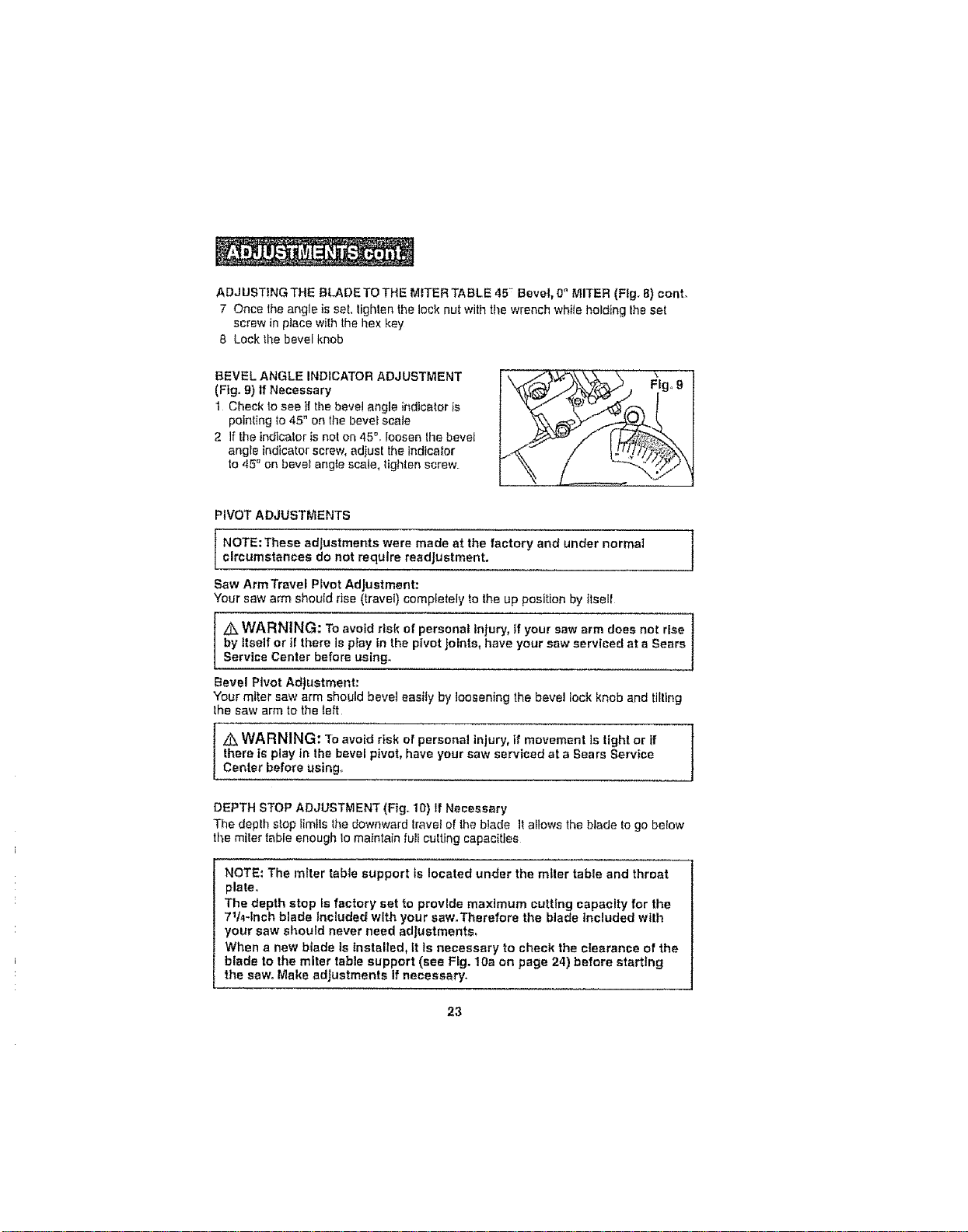
BEVELANGLEINDICATORADJUSTMENT
(Fig.9)IfNecessary
1Checkloseeifthebevelangleindicatorts
pointingto45"onthebevefscate
2 Iftheindicalorisnoton45°.Ioosenthebevel
angleindicatorscrew,adjusttheindicator
to45_onbeve_anglescale,Iighlenscrew
,VOTAOJOST °TS
1 Jcircumstances do not require readjustment.
Saw ArmTravef P_vet Adjustment:
Your saw arm should rise (travel) completely to the up position by ttsell
/k WARNING: TOavoid risk of personal injury, if your saw arm does not rise "t
by Itself or if there is play in the pivot Joints, have your saw serviced at a Sears 1
Service Center before using°
1
Bevel Pivot Adjustment:
Your miter saw arm should beret easily by loosening the bevel lock knob and tilting
the saw arm to the _eft
z_ WARNING: "re avoid risk of personal injury, if movement is tight or if t
there is play in the bevel pivot, have your saw serviced at a Sears Service
J
Center before using_
DEPTH STOP ADJUSTMENT (Fig,. 10) If Necessary
The deplh stop Iimtls the downward travel of the blade It allows the blade to go below
the miter table enough Iomaintain full cutting capacities
NOTE: The miter tabte support ts located under the miter table and throat
plate.
The depth stop is factory set to provide maximum cutting capacity for the
711,_-tnch blade Included with your saw.Therefore the blade Included with
your saw should never need adjustments,
When a new blade Is installed, tt Is necessary to check the clearance of the
blade to the miter table support (see Fig. 10a on page 24) before starting
the saw. Make adjustments If necessary.
23
Loading ...
Loading ...
Loading ...