Loading ...
Loading ...
Loading ...
Part number 550-100-211/0122
– 98 –
(continued)
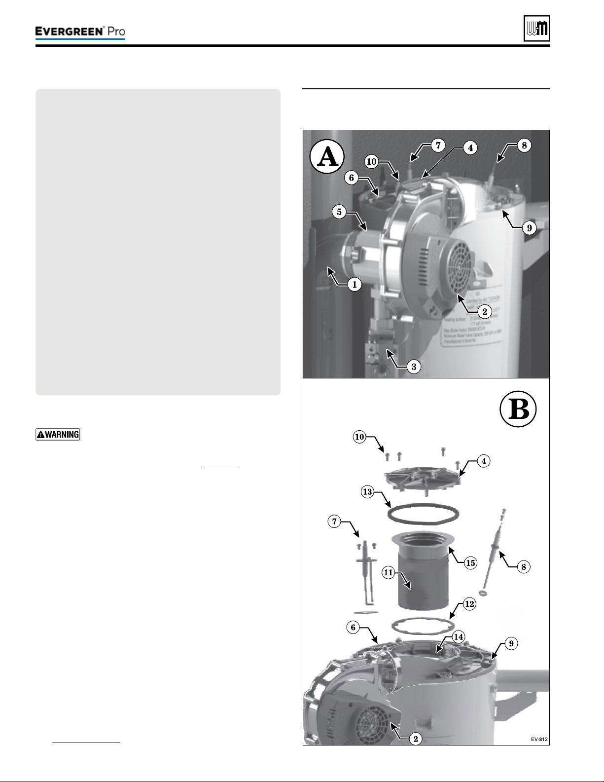
Figure93 Accessing burner, ignition electrode, ame
sense rod and inspection glass assembly
(EVG 220 shown)
LEGEND— Figure93PARTSAandB
A Boiler interior assembled view (Model EVG220 shown;
component locations vary with other models)
B Boiler interior exploded view, showing heat exchanger
cover plate (item6) blower, burner assembly, burner access
cover seal (item13), ignitor, ame sense rod, and sight
glass.
1 Inlet air silencer
2 Blower assembly
3 Gas valve
4 Burner access cover
5 Venturi assembly
6 Heat exchanger cover plate
7 Ignition electrode assembly
8 Flame sense rod
9 Heat exchanger cover plate retainer nuts (6) M6 hex
10 Burner cover retainer screws, M4 Phillips with captive
washers
11 Burner
12 Burner gasket
13 Burner access cover seal
14 Burner gasket sealing surface
15 Burner sealing surface (lower surface of burner ange)
c. Make sure there are no signs of overheating or of ue
gas leakage.
If visual inspection of the heat exchanger indicates
the need, follow the procedures in “Cleaning
the heat exchanger FLUE SIDE or accessing the
burner, when required” on page111 to remove
the heat exchanger cover plate and fully inspect
and clean the interior. Obtain replacement parts
for any components that may be damaged or that
show signs of leakage.
1. Reinstall the burner.
a. Insert a new burner gasket (item12) into the heat exchanger
cover plate (item4).
b. Insert the burner into position.
c. Insert the burner access cover seal into the heat exchanger
cover plate.
d. Place the burner access cover (item4) into position and
secure the four screws (item10).
2. Reinstall ignition electrode assembly and gasket, making
sure that it is correctly positioned. Tighten the two (2) screws
securely.
a. Re-attach igniter cable and ground wire to the ignition
electrode assembly.
3. Reinstall ame sense rod assembly and gasket, making sure that
it is correctly positioned. Tighten the two (2) screws securely.
a. Re-attach the wire to the ame sense rod.
4. Reinstall the burner access panel and air baffle (see
Figure92,page96). Tighten screws securely.
220 /29 9/3 00 /39 9
Loading ...
Loading ...
Loading ...