Loading ...
Loading ...
Loading ...
Part number 550-100-211/0122
– 17 –
220 /29 9/3 00 /39 9
(continued)
1. Follow the same instructions as LP conversion, except using
the correct Natural gas conversion kit, See Figure8,page12 .
2. If LP gas was already selected in the boiler control, the gas
type parameter will need to be adjusted. In the contractor
menu, under the Boiler Settings menu, adjust the “LP Gas”
setting to “NO”.
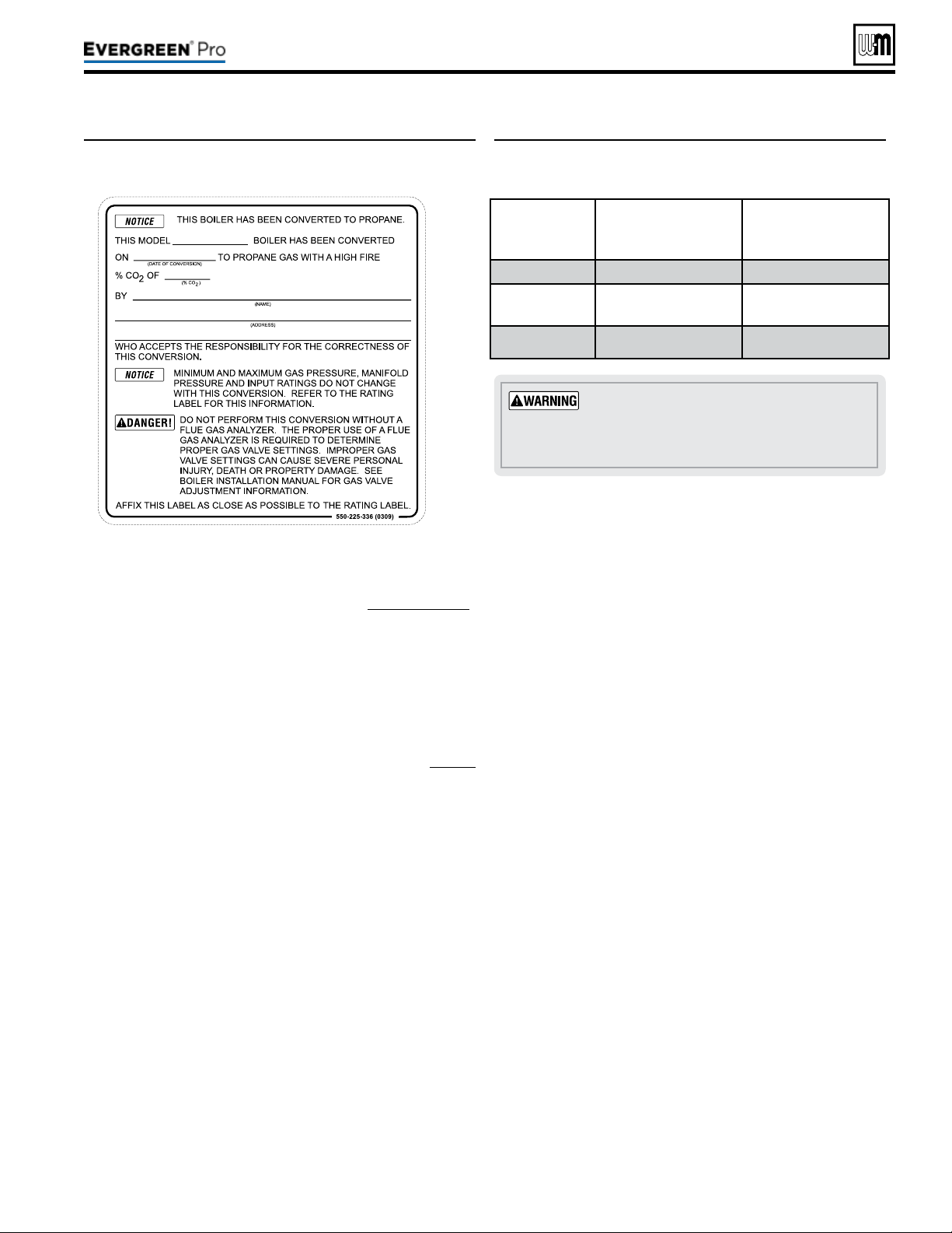
3. Turn throttle screw clockwise until it stops, and then turn
counter-clockwise number of turns per Figure19. Figure19
is intended to make rough adjustment to gas valve to allow
the boiler to re. ey are NOT intended to replace proper
adjustment of combustion valves per instructions on page91
of this manual.
4. Adjust the oset regulating screw in a Clockwise direction
the number of turns listed in Figure19, according to the
boiler model/size.
Thedoormustbeinplaceduringopera-
tion.
DO NOT operate the boiler with the
jacket door removed except for inspection and
testing as directed in this manual.
Figure19 Course adjustment settings—Throttle and
offset adjustments to be made prior to rst
ignition, by size.
Boiler
Model
ThrottleTurns
(Counterclockwise Q from
Bottom-out Position)
OffsetTurns
(Clockwise P
Factory LP Position )
EVG 220NG
1-5/8 3/8
EVG 299/300
NG
3-3/4 1/8
EVG 399NG
3 1/8
Figure18 Installer conversion label
Loading ...
Loading ...
Loading ...