Loading ...
Loading ...
Loading ...
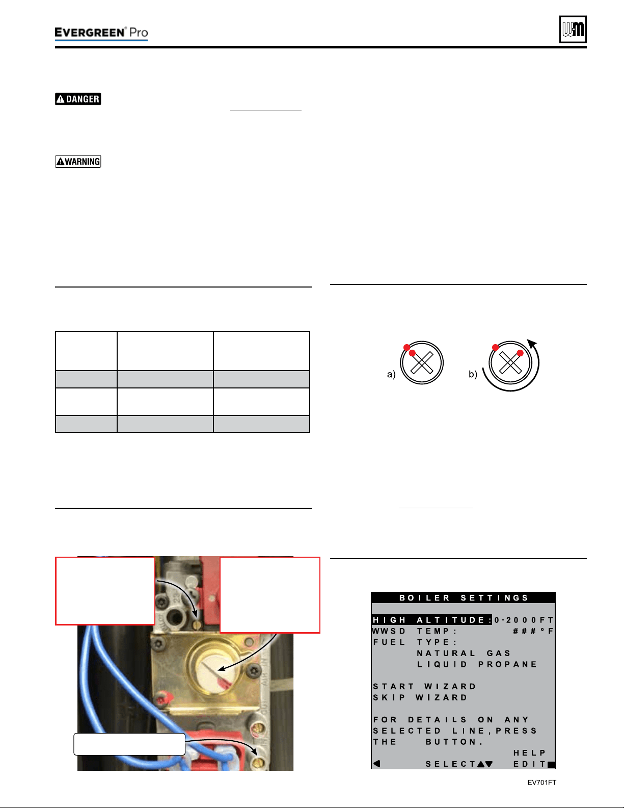
Figure15 Gas valve adjustment locations—ONLY for use
by a qualied technician, using properly working,
calibrated combustion test instruments.
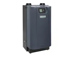
Figure16 Offset regulating screw adjustment—(a)
Marking factory-provided NG position. (b) View
after 3/4 turn CCW adjustment.
Figure17 Evergreen
®
fuel type setting screen
Part number 550-100-211/0122
– 15 –
220 /29 9/3 00 /39 9
Inspect the gas pipe tting connections on the gas
valve and new venturi (Item3, Figure14,page14).
Check the seal of the connections. Failure to
comply will cause a gas leak, resulting in severe
personal injury or death.
Do not check for gas leaks with an open ame —
use bubble test. Failure to use bubble test or check
for gas leaks can cause severe personal injury,
death or substantial property damage.
13. Prior to the boiler’s rst ignition, adjust the throttle adjust-
ment screw by rst turning the screw clockwise (P) until it
bottoms out – do not apply any additional or excess torque.
Adjust the throttle screw in a counterclockwise (Q) direc-
tion with precisely the number of turns listed in Table 1,
according to the boiler model/size.
(continued)
Table1: Course adjustment settings—Throttle and offset
adjustments to be made prior to rst ignition, by
size.
Boiler
Model
ThrottleTurns
(Counterclockwise Q from
Bottom-out Position)
OffsetTurns
(Counterclockwise Q
Factory NG Position )
EVG 220LP
5/8 3/4
EVG
299/300LP
1-3/8 1/4
EVG 399LP
1-5/8 1/4
14. Aer the throttle has been adjusted coarsely, the oset regulat-
ing screw must be adjusted. Remove the sealed, slotted cap
protecting the white oset regulating screw before making
adjustments. It is critical to be precise for the adjustment of
the oset regulating screw. DO NOT attempt to bottom out
the oset regulating screw as was done for the throttle adjust-
ment. Adjustments to the oset regulating screw should be
made from the factory-provided natural gas position.
Adjust the oset regulating screw using the follow-
ing steps, referencing Figure16
:
1a. Use a marker to mark the corner of one tip of the cross on
the oset regulating screw and the corresponding location
on the outside of the screw housing, as shown in Figure16a.
2b. Adjust the oset regulating screw in a counterclockwise (Q)
direction with precisely the number of turns listed in Table
1, according to the boiler model/size.
15. Reconnect wire harness to gas valve.
16. Restore electrical power, turn on gas by opening manual gas
valve and check for leaks.
17. When boiler has not been red, follow instructions on the
initial screens to select propane as the gas type. If natural
gas was already selected in the boiler control, the gas type
parameter will need to be adjusted. In the contractor menu,
under the Boiler Settings menu, adjust the “LP Gas” setting
to “YES”, see Figure75,page76.
18. Before ring, verify that the Boiler Settings are for LP gas,
“Max Rate” for the input (priority) used to re the boiler
GasInletPressure
TestPort
OffsetRegulatingscrew
• Turn clockwise
to increase CO
2
. P
• Turn counter-clockwise to
decrease CO
2
. Q
Note: Must remove cover.
Throttle adjustmentscrew
• Turn counter-clockwise
to increase CO
2
. Q
• Turn clockwise to
decrease CO
2
. P
Loading ...
Loading ...
Loading ...