Loading ...
Loading ...
Loading ...
Part number 550-100-211/0122
– 42 –
Figure50 and Figure51 show typical installations of the system expansion
tank. Always locate the air separator and expansion tank as shown in the
suggested piping drawings, beginning on page43.
Ensure that the expansion tank size will handle boiler and system water
volume and temperature. Allow 4.6 gallons for
Evergreen
®
220, 7.0 gal-
lons for
Evergreen
®
299/300 and 6.7 gallons for Evergreen
®
399. See
tank manufacturer’s instructions and ratings for details. Additional tanks
may be added to the system if needed to handle the expansion. ese tanks
may be installed by connecting to tees in the system piping.
Undersized expansion tanks cause system water to
be lost from the relief valve and makeup water to be added
through the ll valve. Eventual boiler failure can result due
to excessive make-up water addition. Always locate the cold
waterllconnection at the expansion tank. Never locate
this elsewhere in the system.
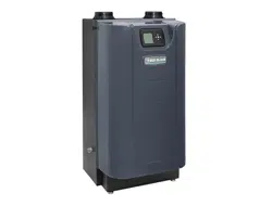
Diaphragm-orbladder-typetank:
Refer to Figure50 for suggested piping when using a diaphragm- or
bladder-type expansion tank.
Diaphragm-orbladder-typeexpansiontank — Con-
trol llpressure with the tank air charge pressure. Always
check pressure and charge tank with tank removed from
system to be sure reading is accurate. Boiler relief valve is set
for 30 PSIG. Operating pressure of system, aer temperature
expansion above cold ll pressure, should not exceed 24 PSIG
to avoid weeping of relief valve.
Install an automaticairvent on top of the air separator, per separator
manufacturer’s instructions.
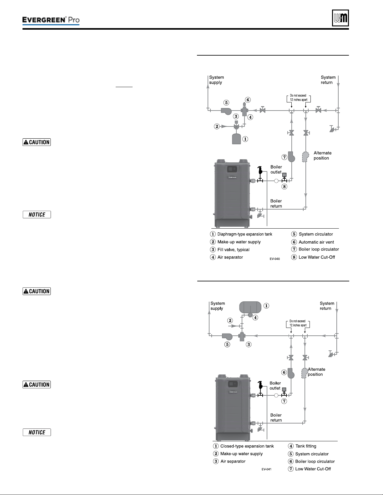
Closed-typeexpansiontank:
DO NOT use a closed-type tank if connecting to a water
heater that is equipped with an automatic air vent.
Figure51 shows suggested piping when using a closed-type expansion tank,
in which the air is directly in contact with tank water.
Connect piping (½” or ¾”) from the air separator top outlet to the tank
tting. Slope any horizontal piping a minimum of 1inch per 5feet of
horizontal pipe.
Always use a tanktting, such as the B&G Ta n kt ro l or Taco Taco-Trol
(shown). e tting reduces gravity ow of water in the piping to the tank,
avoids air bubbling through the tank water, and provides the proper ll
height in the tank.
Correctallleaks in the system or tank piping. Leaks allow
air to escape from the system and will cause water-logging
of the tank. is will result in water loss through the boiler
relief valve due to over-pressurization. NEVER use an
automatic air vent in a system equipped with a closed-type
expansion tank. e air removed from the system will cause
water-logging of the expansion tank.
Closed-type expansion tank — Follow tank manu-
facturer’s instructions for llingthetank. Typical tank
sizing provides for approximately 12 PSIG when the tank
is lled to the normal level and system water is cold. Note
that boiler relief valve is set for 30 PSIG. Operating pres-
sure of system, aer temperature expansion above cold ll
pressure, should not exceed 24 PSIG to avoid weeping of
relief valve.
Figure50 Piping to diaphragm (or bladder) type
expansion tank
Figure51 Piping to closed -type expansion tank
220 /29 9/3 00 /39 9
Loading ...
Loading ...
Loading ...