Loading ...
Loading ...
Loading ...
Part number 550-100-211/0122
– 56 –
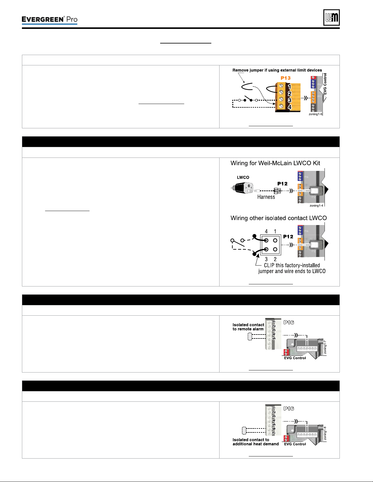
TocauseAUTOMATICreset:TerminalBlockP13#3(EVG control module, left side)
EVGcontrolwillresetautomaticallyaftercircuitisinterrupted.
1. Remove factory-installed jumper and connect isolated contacts of external
limits across P13 pins3 and4 to cause the control to shut down the boiler on
limit opening, then automatically restart 150 seconds aer the limit closes.
2. See drawing at right and wiring diagram (Figure65,page59).
See Figure65,page59 for details.
H. Low water cuto – WHEN REQUIRED
TerminalBlockP12(EVG control module, left side)
1. Install a low water cut-o when required.
2. Wiring Weil-McLain LWCO Kit:
a. When possible, use the Weil-McLain Low water cut-o kit listed in the
back of this manual. It includes a probe-type low water cut-o and pro-
vides a simple harness connection for the wiring.
b. Connect as shown at top right and in the control wiring diagram
(Figure65,page59).
c. e Weil-McLain Low water cut-o kit is included with the boiler.
3. Wiring another LWCO — must have isolated contact:
a. Other low water cut-os can be used with the EVG only if the device uses
an isolated contact for the LWCO function.
b. Connect as shown at bottom right.
See Figure65,page59 for details.
I. Alarm contacts – OPTIONAL
TerminalBlockP16#4(EVG control module, top left)
1. e control’s alarm dry contact (P16, terminals 4 and 5) closes when the
boiler enters manual lockout only.
2. Connect these terminals for remote alarm notication.
3. Contact electrical ratings: 24VAC or less; 0.5 amp or less.
See Figure65,page59 for details.
J. Additional heat demand contacts – OPTIONAL
TerminalBlockP16#6(EVG control module, top left)
1. e control module can be set to activate another heat source using its ad-
ditional heat demand dry contacts through terminal block P16 pins6 &7.
2. Connect these terminals to call for heat from the other heat source.
3. Contact electrical ratings: 24VAC or less; 0.5 amp or less.
4. Set the control to activate the heat demand contacts as needed.
5. See EVG Advanced Manual to congure.
See Figure65,page59 for details.
(see wiring diagram, Figure 65, page 59)(continued)
220 /29 9/3 00 /39 9
Loading ...
Loading ...
Loading ...